Table of Contents
Advertisement
Quick Links
Advertisement
Table of Contents

Subscribe to Our Youtube Channel
Related Manuals for Phelcom Eyer

Summary of Contents for Phelcom Eyer
-
Page 3: Table Of Contents
3.2.1 Device start screen and access 3.2.1.1 Patients 3.2.1.1.1 Creating patient profiles through Eyer ® 3.2.1.1.2 Patient personal information 3.2.1.1.2.1 Info 3.2.1.1.2.2 Removing a patient information through Eyer ® 3.2.1.1.2.3 Exams 3.2.1.1.2.4 Creating exams through Eyer ® 3.2.1.1.2.5 Image capture screen 3.2.1.1.2.6 Captured images... - Page 4 13. Electromagnetic Safety Standards 13.1 Supplier declaration and guidelines - Electromagnetic emissions 13.2 Supplier declaration and guidelines - Electromagnetic immunity 13.3 Minimum distance separation recommended for RF mobile device and Eyer ® 13.4 Radio Frequency interference 14. Biocompatibility 15. Glossary and symbols 16.
-
Page 5: Compliance
1. Compliance Phelcom Technologies developed this device according to worldwide quality standards, prioritizing patient and operator safety, electromagnetic compatibility and friendly operational flow, thus making Eyer ® Retinal Camera safe, reliable and robust, meeting the most varied demands of fundus imaging for diagnosis and screening purposes. -
Page 6: Intended Users
● Never disassemble the device, since it may damage optical and electronic parts, as well as fragile mechanisms. ● Contact Phelcom technical support in case there are any problems related to the device; ● Eyer Retinal Camera must be used either in clinical/hospital locations. -
Page 7: Contraindications And Limitations
Due to small size and portability Eyer ® Retinal Camera can also be used for homecare visits and remote screening camps. 1.6. Contraindications and limitations Because prolonged intense light exposure can damage the retina, the use of the device ocular examination should not be unnecessarily prolonged, and the brightness setting should not exceed what is needed to provide clear visualization of the target structures. -
Page 8: Overview
In case of any information, doubt, suggestion or complaint about device components, please contact Phelcom. Always count on the technical staff to help and guide you, maximizing device usefulness . 2.2. -
Page 9: Setup And Electrical Connections
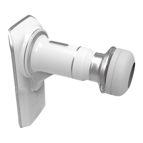
Before first use, qualified and supplier-authorized technicians must install smartphone and application to assure the device works perfectly. Contact Phelcom for further information on initial setup. Phelcom staff may also provide remote access to make maintenance and application troubleshooting possible. Eyer ®... - Page 10 Figure 1: Device on its accessory base. Eyer ® application setup for smartphones works as the steps described in section 2.2. Minimum requirements of the smartphone follow specified in Table 1. Table 1: Minimum requirements for smartphone. Operating System Android Nougat 9.0 Pie Screen 6.1-inch AMOLED 1440X3640 (~550 ppi)
- Page 11 Water resistance IP 68 rating Dimensions 149.9 x 70.4 x 7.8mm Weight 157 g According to minimum requirements, most adequate smartphones available on market are Samsung Galaxy S10.
-
Page 12: Eyer
® 3. Eyer Eyer ® is simple and user-friendly. Device and application details and operation flow are presented below: 3.1. Device features Figure 2, figure 3, figure 4, figure 5 and figure 6 present the feature list below: 1. Eyer ® Retinal Camera with integrated smartphone;... -
Page 13: Operation
3.1.1. Operation After acquiring Eyer ® , the user must access https://eyercloud.com/us_register to register an account to the system. All device operation is done through the application installed in the smartphone, which is used for commands, controls, to visualize operations and results, as well as to access external systems to share and store images. -
Page 14: Device Start Screen And Access
Captured information and exams can be safely synchronized by SMB/CIFS, DICOM or FTP connections allowing the visualization of the data and exams outside Eyer application. For patient data synchronization consult the section 3.2.1.3.4 Servers for details. - Page 15 Figure 8: Device start screen with top Figure 9: Quick Access Tools. android bar. Figure 10: Wi-Fi details. Figure 11: Quick access apps.
- Page 16 Access application by an icon on the central screen, figure 8. Figure 12 depicts the program loading screen. Figure 12: Initial system loading screen. A screen for USB device permission displays at the end of the process, use it as default and click “OK”, figure 13. Select the language, figure 14, and the terms of use and privacy policy display, figure 15.
- Page 17 Figure 13: Setting USB device as default. Figure 14: Language selection. Figure 15: Accept Terms of Use. Figure 16: Application first access screen.
- Page 18 Figure 17: Clinic selection to carry out exams. Figure 18: Application access screen. After login, a screen displays, figure 19. It enables accessing all system functions: patients, exams and options. Click the synchronization icon , figure 19, to check transfer status, figure 20. Figure 19: Start screen to access system functions. Figure 20: Device transfer status.
-
Page 19: Patients
Access option 1, “Patients”, in the main screen, figure 19, to register, visualize, alter information, as well as carry out exams and diagnostics through patient information. 3.2.1.1.1. Creating patient profiles through Eyer ® Selecting icon 1, figure 19, displays a screen as in figure 21. Here, a list of registered patient names displays. - Page 20 Figure 21: Opening screen for the “PATIENTS” Figure 22: Screen for creating patient profile. option, figure 19. Click to sort the profiles list and choose one option: recent, ascending or descending, figure 23. Figure 23: Filter to exhibit patient profiles.
-
Page 21: Patient Personal Information
Info Each patient registration form, figure 24, is accessible through the screen depicted by figure 21, or automatically, after creating a new patient profile (section 3.2.1.1.1 Creating patient profiles through Eyer ® ). First provided information is compiled in the “info” tab, with the following functions: 1. - Page 22 3.2.1.1.2.2. Removing patient profile through Eyer ® Select icon 3, figure 24, to remove a patient form. Click the “remove” option in checkbox, figure 25. Do not select “remove remote” to remove the capture from Eyer ® and keep it on your servers, figure 26.
- Page 23 Figure 28: Exams tab. 3.2.1.1.2.4. Creating exams ® through Eyer Select icon in “info” or “exams” tab, figure 28, and the screen in figure 29 displays. “Info” tab contains the patient name, date and time of exam (click in any section field to edit), a field to write...
-
Page 24: Image Capture Screen
3.2.1.1.2.5. Image capture screen Select icon , figure 29, and a screen, figure 30, opens. Its icons are specified according to their functions. Figure 30: Image capture screen. Figure 31: Fixation targets. Figure 32: Anterior segment capture screen. - Page 25 Patient will see a white light flash. There is no image capture at this point, but the device will adjust focus of the examined eye. Remove Eyer ® from patient’s face. It is possible to photograph after a few seconds if the pupil is not dilated with eye drops.
- Page 26 Lighting scale varies from 1 to 5. Click the icon to adjust lighting through the adjustment bar. Adjusted Emitting Camera Indication of use Functional Level Light level Gain characteristics 100% Very clear eyes or retinal Dark photos tissues with high suitable for light reflection abnormal colored retinal...
-
Page 27: Captured Images
Internal fixation target select By clicking the icon, 9 circles display on the capture screen, figure 31. Internal fixation target determines which eye area is centered while capturing the image. The larger circles portray: macula (center) and optical nerve (left for left eye capture;... - Page 28 Figure 33: Images captured during exam. Figure 34: Checkbox for images. Figure 35: Screen for sending image via DICOM/FTP.
- Page 29 1. Share: sends images to external platforms. Click and hold on the images to select until a blue square frame shows around them. Click the icon , then “share” and choose how to send the file. 2. Transfer: screen which presents a summary of exams and images to send, with success and failure statistics and the available server list, figure 35.
- Page 30 Click and hold over targeted images, then a blue square frame shows around them. Click , then panoramic. Confirm generation and wait. 4. Texture: images with filters to assist identifying lesions. Click and hold over targeted images, then a blue square frame shows around them.
- Page 31 5. Stereo: dynamic image that enables better viewing of the optic nerve. Click and hold over targeted images, then a blue square frame shows around them. Click , then stereo. Confirm generation and wait.
- Page 32 6. Delete images: Permanently delete an image or set of images. Check section 3.2.1.1.2.8. Removing Images through Eyer ® to delete a magnified image. Click and hold over targeted images to remove, click the icon , then “Delete images”, then “yes”.
-
Page 33: Synchronization Failure
3.2.1.1.2.6.1. Synchronization failure In case of exam synchronization failure, the symbol , figure 36, displays. Click the icon to check the cause. “Synchronization Status”, figure 37, displays pointing server and send errors. Touch the message in red and check synchronization details for further information, figure 38. Figure 36: Synchronization failure. -
Page 34: Image Analysis And Editing Through Eyer
Figure 37: Synchronization details. Figure 38: Synchronization status. 3.2.1.1.2.7. Image analysis editing through Eyer ® Click the capture of interest to analyse images via device. A screen with expanded view displays, figure 39. Use icon to edit. Figure 39: capture expanded image. -
Page 35: Cropping
3.2.1.1.2.7.1. Cropping Select icon to crop an image and choose a rectangular or elliptical shape, then drag it to the area of interest, figure 40. Complete the crop through icon Figure 40: Editing on clipping screen. 3.2.1.1.2.7.2. Image Measurement Click the icon to measure images. -
Page 36: Image Rotation
3.2.1.1.2.7.3. Image Rotation Select the icon and drag the scale towards the aimed direction to rotate an image, figure 42. After completing, select the icon Figure 42: Image rotation screen. 3.2.1.1.2.7.4. Levels Drag the icon scale bar to adjust image brightness level or icon adjust contrast, figure 43. -
Page 37: Removing Images Through Eyer
In the patient exams list, figure 28, slide leftwards and select “remove”, figure 44. Do ® not activate “remove remote”, figure 45, to delete the exam only from Eyer and not from other configured servers. Activate it to delete from all servers, figure 46. -
Page 38: Creating And Editing Diagnosis Through Eyer
Figure 45: Removing exam in Eyer ® Figure 46: Removing exam in Eyer ® configured servers. 3.2.1.1.2.10. Creating and editing diagnosis through Eyer ® After image capture, “Info” tab, figure 29, enables the field “diagnosis” to insert technical reports, figure 47. Icon creates a diagnosis. - Page 39 When a diagnosis is created, the screen portrayed in figure 48 opens in the “info” tab. Include, in the editable field “diagnostic Hypothesis”, the disease hypothesis in the field “ICD pattern” and, for non-catalogued diseases, use the field “other”. Figure 48: Diagnosis information input. All images will be selected in the “images”...
- Page 40 Report file will display below the diagnosis field, figure 50: 1. Send report to one of the configured servers; 2. Edit report information; 3. Generate file and 4. Delete diagnosis. Figure 50: Diagnosis linked to the exam. Screen portrayed in figure 51 displays when icon (generate report) is selected.
-
Page 41: Sending Files By Email
Figure 51: Application-generated report. Figure 52: File options. 3.2.1.1.2.11. Sending files by email Access “Send file”, figure 52, then choose “Gmail” option, regardless of the user’s email server, figure 53, and follow application instructions. -
Page 42: Device Printer Setup
Figure 53: Sending files by email. 3.2.1.1.2.12. Device printer setup Access “open with”, figure 52, choose the local printer application, figure 54, and follow the instructions. A Wi-Fi printer is required and must be turned on to show in the available printers list. Figure 54: Print PDF. -
Page 43: Exams
3.2.1.2. Exams Exams may be consulted as in section 3.2.1.1.2.2 Exams or by any other direct way, as the start screen, figure 19, icon 2. When directly activated, a list of patients scheduled for the present date displays, figure 55, according to the schedule. Click the date and choose the date to check or edit. -
Page 44: Options
3.2.1.3. Options Option 3 on the application start screen refers “options” button, figure 19, which enables visualizing information on the clinic, system, device and servers, figure 56. Figure 56: ”Options” tag available functions. 3.2.1.3.1. Clinic Option 1. “Clinic”, figure 56, displays information on the accessed clinic, figure 57. -
Page 45: System
3.2.1.3.2. System Option 2. “System”, figure 56, displays options to visualise system logs, default settings and language, as well as terms and conditions, figure 58. Figure 58: System screen. 3.2.1.3.2.1. Logs Function 1. “Logs”, figure 58, presents options to control the registry, which is used diagnose system... -
Page 46: Defaults
3.2.1.3.2.2. Defaults Access option 2, figure 58, to visualize device default settings. A screen as in figure 60 displays. Click the icon to change defaults, figure 61. Figure 60: Device default settings. Figure 61: Edit device defaults. 1. Lighting intensity: sets image lighting level - default lighting level for image capture screen is 3;... -
Page 47: Language
1. Archive period (days): determines, in days, how long the information remains available in the device. 3.2.1.3.2.3. Language , option 3, depicts where to Figure 58 ® Eyer language: Portuguese (Brazil), English (US) and Spanish, figure 62. Figure 62: Device language selection. 3.2.1.3.2.4. -
Page 48: Device
Figure 63: Terms of Use. Figure 64: Privacy Policy. 3.2.1.3.3. Device The option “device” contains information on the device, item 4, figure 56. When selected, there are three available options: 1. Calibration, 2.About, 3. User Manual, figure 65. -
Page 49: Calibration
Figure 65: Technical information on the device. 3.2.1.3.3.1. Calibration Click option “Calibration”, figure 65, to proceed to the screen as in figure 66. ● Direct the device towards a flat and clear surface. ● Activate “start” button, figure 66, and wait for the device to make technical adjustments. -
Page 50: About
3.2.1.3.3.2. About Access information on the device through the screen portrayed in figure 65, section 2. User will be directed to the screen in figure 67 which contains: 1. Software version: information on operation application version; 2. Firmware version: version of the software on device frame; 3. -
Page 51: Common Servers Setup
Select button , figure 68, to add a new server. Select the server type to synchronize, figure 69, and fulfill information as described in item 3.2.1.3.4.1 Common server setup. Figure 68: Servers list. Figure 69: Option to create servers. 3.2.1.3.4.1. Common server setup Any type of server requires defining information, figure 70: 1. -
Page 52: Dicom Servers Setup
Figure 70: Common server setup. Figure 71: Synchronization action options. 3.2.1.3.4.2. DICOM servers setup server information exam storage (Archive AE) or worklist server information, figure 72, to use DICOM servers. 1. AE Title: Application identification in the system; 2. AET: Server identifier; 3. IP: server IP; 4. -
Page 53: Ftp Servers Setup
3.2.1.3.4.3. FTP server setup Fill information in as in figure 73 to use FTP servers. 1. Server address; 2. Server port; 3. User name; 4. Password; 5. File format transferred (DCM or JPG). Fifigure 73: FTP server setup. 3.2.1.3.4.4. SMB/CIFS server setup Fill information in as in figure 74 to use SMB/CIFS servers Server address;... - Page 54 Diverse fields are filled in for that standard, as the TAGS that follow below: ● PatientID → Built from the clinic medical record number, with a prefix defined in the field “DICOM Prefix” in Eyer® systems screen. Example: For a clinic registered with a CNS medical record, a DICOM file with PatientID value “phelcom_cnsPaciente”...
-
Page 55: Shutdown Procedure
3.2.2. Shutdown procedure After the operator performs the exams, he must finish the operation by pressing the button and confirm by Selection “YES”. Figure 75 - Finish the operation. The Application will enter the home screen and recommends if for short periods between exams, leave the equipment on standby, quickly pressing the right side button ofthe smartphone leaving it on the reset screen. - Page 56 Figure 76 - Turn off the equipment...
-
Page 57: Posterior Segment
4. Carrying out exams 4.1. Posterior segment Provided the knowledge on handling Eyer ® integrated systems, access the image capture screen, figure 30, then follow steps below to capture images. ● Adjust device parameters according to section 3.2.1.1.2.5 Image capture screen;... - Page 58 Figure 77: Device positioning for retina image capture. Captured image displays for a few seconds then is immediately stored in gallery, figure 78, enabling capture screen for new photos. Figure 78: Example of Posterior segment capture.
-
Page 59: Anterior Segment
The other fingers rest on the patient’s head until the capture is complete; ● Hold Eyer ® with the right hand; ● Ask the patient to open both eyes wide and cover the eye that will not be examined with a cupped hand;... - Page 60 It is not possible for the user or operator to carry out maintenance in this device. Manufacturer recommends regular preventive maintenance inspections made by Phelcom. Inspection must be done every year to help detect eventual damage, increase device safety and lengthen its service life.
-
Page 61: Packing, Storage, Transportation, Site Selection, Operation And Environmental Conditions
● Conform to the safety labels affixed to device package; ● Avoid impacts (shock, falls, etc.) that may cause mechanical, optical and/or electronic damage, resulting in loss of calibration made by Phelcom; ● Location for storage, transport and operation must have controlled environmental conditions. -
Page 62: Accompanying Parts And Accessories
7. Accompanying parts and accessories Following parts and accessories compose the device, figure 80: Figure 80: Equipment parts and accessories. 7.1. Accessories 1. Eyer Retinal Camera; 2. Dock station (charging station); 3. Eyecap; 4. Lens Protector; 5. Storage case; 6. Cleaning cloth;... -
Page 63: Disposal
2002/96/CE, through recycling companies or licensed solid waste disposal in the country of operation. Disposal of device or parts does not need to be sent to the factory. Consult Phelcom local authorized supplier before disposal. Users are responsible for disposal of Eyer ®... -
Page 64: Cables And Connections
● Smartphone charge: Plug a charger connected to the power grid, figure 83, in the Eyer ® USB-C port, figure 84. ● Accessory base charge: Install the power cable at the bottom of the accessory base, figure 85, and plug Eyer ® to charge, figure 86. ® Figure 83: Eyer connected to charger. - Page 65 Figure 85: Cable connected at the bottom of the ® Figure 86: Eyer positioned for accessory base accessory base. charge. Power grid isolation is possible through the smartphone charger while the battery charges. Always use the original charger in good conditions.
-
Page 66: Technical Data
Resolution Camera resolution 12 MP Image resolution 1600 x 1600 px Chart 1 shows a graphic about Eyer ® emission spectrum for retinal and anterior segment imaging and Chart 2 shows a graphic about Eyer ® emission spectrum in the preview mode. -
Page 67: Electrical Characteristics
Chart 1: Eyer® emission spectrum for retinal and anterior segment imaging. Chart 2: Eyer® emission spectrum in the preview mode. 10.2. Electrical characteristics Patient exposure to any energy related risk coming from the power grid is prevented by a software lock that unables exam procedures while charging. Table 3 presents information on the device and its classifications. - Page 68 Supply Voltage 5Vcc (supplied by smartphone) Power in standby: 0,15W Power in Power operation: 2W Maximum current 500 mA Frequency 0Hz (continuous current) Dimensions (height x width x length) 185mmX85mmX160mm Weight 600g Family/Model Eyer Retinal Camera / NM-STD Software/App Eyer ®...
-
Page 69: Warning
11. Warning You have acquired a high technology device made by a Brazilian company. That means you can access our after sales service through the contacts in the last page of this Guide. -
Page 70: Troubleshoot Guide
This chapter presents some operational issues the device may present in use. User can check for technical specifications in table 4 that will serve to correct simpler issues or to facilitate contact with Phelcom technical support. Table 4: Technical specifications for operational issues... - Page 71 Low quality of examination images patient’s eye. Read this User Manual carefully and follow suggested instructions and recommendations. Check if the correct Eyer App, in its updated version, is selected. Application does not work Reinstall the Eyer App. Click on “forgot password” to generate a new password.
-
Page 72: Electromagnetic Safety Standards
Phelcom. If the performance of Eyer Retinal Camera is lost or degraded due to electromagnetic disturbances, it may cause unexpected or adverse operation of this device. -
Page 73: Supplier Declaration And Guidelines - Electromagnetic Emissions
Replacement cables may only be purchased at Phelcom. the use of Accessories, any converters or cables which are not specified in this user manual or have not been purchased as spare parts from Phelcom can result in increased emissions or reduced immunity of the device. -
Page 75: Supplier Declaration And Guidelines - Electromagnetic Immunity
13.2. Supplier declaration and guidelines - Electromagnetic immunity Eyer® maintains basic safety and performance when used in the electromagnetic environment specifies tables 6 and table 7. The customer or the user of the device should ensure that it is used in such an environment. - Page 76 3 Vrms 150 KHz to communication equipment must 150 KHz to 80 Conducted RF 80 MHz not be used near any Eyer part, IEC 61000-4-6 & 6 Vrms including cables, within a shorter & 6 Vrms ISM separation distance than...
- Page 77 RF disturbances are controlled. The customer or the user of Eyer Retinal Camera can help prevent electromagnetic interference by maintaining a minimum distance between portable and mobile RF...
-
Page 78: Radio Frequency Interference
= 1,2√P d = 1,2√P d = 2,3√P 0,01 0,12 0,12 0,23 0,38 0,38 0,73 13.4. Radio frequency interference Eyer ® follows the regulation IEC 60601-1-2:2014, following all applicable requirements regarding electromagnetic compatibility, provided that local environmental limitations are met. -
Page 80: Biocompatibility
14. Biocompatibility Phelcom declares that the material used in the applied part of the device Eyer ® certified by ISO 10993-1 - Biological evaluation of healthcare products, thus offering no risk regarding its use. The Eyecap accessory is manufactured by Phelcom Technologies, and has a use by date of 5 years. -
Page 81: Glossary And Symbols
15. Glossary and symbols This section presents all the symbols related to device safety and their meanings, table 9, as well as the labels on its protective package. Table 9: Labels, markings and symbols. MARKING SYMBOL MARKING SYMBOL Fragile; handle Operator's manual with care Keep away from Class II equipment... - Page 82 Waste electrical Type BF Applied and electronic Part disposal Federal law restricts this device to sale by or General warning on the order of a sign physician or licensed practitioner...
-
Page 83: Cybersecurity Information
The smartphone is limited to install Android operating system and is dedicated for Eyer Retinal Camera, for the risk of viruses and other malwares, users must install and enable anti-virus software and follow the suggestion of third-party software (including virus updates) to update it. -
Page 84: Term Of Warranty
Phelcom is not responsible for personal injuries, lesions or wounds resulting from device misuse. Phelcom legal liability referring to this device and its use is limited to the purchase value paid by the Customer. In case the commercial relation to Phelcom is not a purchase and sale agreement, the applicable warranty and responsibility terms shall mandatorily be defined in... - Page 85 Passarini Regulatory Aairs of America LLC 201, South Biscayne Boulevard Suite 1200 - Miami Center Building Miami , FL US 33131 Phone: 886 2641043 Ext Fax: 866 2641043 Email: usagent@rapassarini.com.br PHELCOM EYER - NM-STD USER MANUAL - REVIEW 7 06/09/2022...
Need help?
Do you have a question about the Eyer and is the answer not in the manual?
Questions and answers