Table of Contents
Advertisement
Quick Links
Advertisement
Table of Contents

Related Manuals for martens GTL723

Summary of Contents for martens GTL723
- Page 1 Operating Manual Clamp-on Temperature Sensor GTL723 Save for later reference!
-
Page 2: Table Of Contents
Clamp-on Sensor GTL723 Table of contents Proper use (application areas) ......................1 Safety signs and symbols ........................2 Safety instructions ..........................3 Product liability and guarantee ......................3 Standards and directives ........................3 Product description .......................... 4 Delivery content ........................... 4 Operating principle .......................... -
Page 3: Proper Use (Application Areas)
Clamp-on Sensor GTL723 1 Proper use (application areas) Detailed information on the application area can be found in the Chapter Product description The operating safety of the device is ensured only with proper use and observation of the information given in the operating instructions. -
Page 4: Safety Signs And Symbols
Clamp-on Sensor GTL723 Safety signs and symbols Warning instructions: Warning! This symbol warns against immediately threaten- ing danger, death, severe physical injury or serious material damage if instructions are not followed. Danger Attention! This symbol warns against possible dangers or dangerous situations, which can cause damage to the de- vice itself or to the environment if instructions are not followed. -
Page 5: Safety Instructions
Clamp-on Sensor GTL723 Safety instructions Read the product description before bringing the device into operation. Ensure that the product is fully suitable for the applications in question. The operator is responsible for the problem-free operation of the device. The operator is obliged through-... -
Page 6: Product Description
Clamp-on Sensor GTL723 2 Product description The GTL723 pipe clamp-on sensors are especially useful as an Alternative to invasive and inline-measuring procedures for monitoring sterilization processes. Without disturbing the process, the special clamp-on mechan- ics make the systems flexible, absolutely dead spot-free, and usable without high installation costs. This meas- uring procedure permits high-precision results. -
Page 7: Design Oft He Measurment System
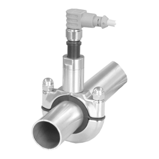
Clamp-on Sensor GTL723 Design of the measurement system The GTL723 measuring system consists of an RLA piping adapter and a GTL723 measuring insert. Sensor insertion with round plug M12, 360° turn able Insertion GTL723 Type plate insertion GTL723 Type plate... -
Page 8: Step Responce Of Clamp-On Sensor
30 °C Medium Water Mounting direction Acc. to position 1, 3.1 Mechanical mounting Table 2 Reference condition for step response GTL723 step-response (without thermal compound) Medium (Water) GTL723 GTL723 with activated pipe wall correction Figure 5 Step-response (T ) in water, without thermal compound... -
Page 9: Mounting And Electrical Installation
Clamp-on Sensor GTL723 3 Mounting and electrical installation Mechanical mounting The RLA pipe clamp sensors are available in three sizes. The adapters are adjusted to the pipe diameter (DN10 to DN80) with different highly heat- resistant silicone inserts. Frame size (Bg) Pipe Ø... -
Page 10: Mounting Notes
Clamp-on Sensor GTL723 Mounting notes min. 15 cm Flow direction min. 15 cm min. 15 cm Figure 7 Permissible types of mounting Position Characteristics Ideal: Achieves the best result, since there are no bubbles, deposits, or rising lost heat in the pipes to distort the measuring result. -
Page 11: Electrical Installation
Clamp-on Sensor GTL723 Electrical installation The electrical connection is to realized using the M12 round connector pin 1 (+) and 2/3 (-). For the wiring see Figure 8 Connection diagram. Supply voltage acc. To DIN EN 60664-1, SELV, PELV The device must be installed only by a qualified electrician. The national and international regulations for the installation of electrical systems of the relevant operator country apply. -
Page 12: Connction Diagram
3.2 – Gradient correction Number input ##.## - ##.## -10,00..+10,00 0,00 % Table 5 Operating structure GTL723 *The free programmable measuring range must be in range -20.0…160 °C. The minimal span must be 50 °C. 10 / 19 BA_MA_GTL723_EN_V2.04... -
Page 13: Commissioning, Maintanace And Servicing
Clamp-on Sensor GTL723 Connection diagram View at the plugs: Figure 8 Connection diagram 5 Commissioning, Maintenance and Servicing Commissioning Be sure that the pipe clamp sensor is flush with the pipe. Be sure that the M-12 connector is screwed on correctly and the cable is not pulling on the sensor. -
Page 14: Calibration / Adjustment
Clamp-on Sensor GTL723 Calibration / Adjustment The series GTL723 sensors are calibrated in a way so that the measurement errors are within the target values of the calibration data below (specifications for the temperature sensor). Upon request, this sensor can also be delivered with a certificate of calibration. -
Page 15: Faultfinding
Clamp-on Sensor GTL723 Proposed calibrating system GTL-sensor insertion Retaining clamp Calibrated reference sensor Heated insert external heating Figure 9 Proposed calibration system The insert is constructed in a way to position the calibrated reference sensor very closely under the active heating surface, so that it may be used as a reference meter or regulator of the application temperature. -
Page 16: Technical Data
Clamp-on Sensor GTL723 7 Technical Data Temperature sensor Pt100 A class, acc. to DIN EN 60751 Measuring range -20..+100 °C, temporary 160°C <30 min Min. measuring range 50 °C Ambient temperature -20..+60 °C Electrical connection 10…30 V DC, 2-wire connection... - Page 17 Clamp-on Sensor GTL723 Maximum ambient temperature Figure 10 Maximum ambient temperature 15 / 19 BA_MA_GTL723_EN_V2.04 BA_MA_TC125_EN_V0.13...
-
Page 18: Mechanical Desing / Dimensions
Clamp-on Sensor GTL723 Mechanical design / dimensions Clamp-on sensor GTL723 Clamp-on adapter RLA Figure 101 Dimensions GTL723, RLA Frame size Pipe [mm] [mm] [mm] [mm] 13,0..19,9 20,0..33,9 34,0..53,0 60,3..75,9 76,0..88,9 Table 8 Frame size and dimensions RLA 16 / 19... -
Page 19: Ordering Code
Pipe wall correction for ss-type pipes Not active Active, without usage of thermal compound Active, with usage of thermal compound Options Without options Certificate APZ3P 3.1 testing certificate, accuracy (30/60/90°C) Table 9 GTL723 Ordering code 17 / 19 BA_MA_GTL723_EN_V2.04 BA_MA_TC125_EN_V0.13... - Page 20 Clamp-on Sensor GTL723 Clamp-on adapter Pipe diameter DIN11850 DIN11866 ISO 1127 ASME-BPE Bg.1 120 (12,0mm) DN10 ½“ 130 (13,0 / 12,7mm) DN10 135 (13,5mm) 172 (17,2mm) DN10 DN10 180 (18,0mm) DN15 ¾“ 190 (19,0 mm) DN15 Bg.2 213 (21,3mm) DN15...
-
Page 21: Accessories
Syringe containing 3 ml+ pipette Color silver grey GTL Configuration Programming GTL723 via PC tool Table 11 optional accessories For the evaluation of Pt100 signals, we recommend our control cabinet transmitters, temperature limit transmit- ters, temperature and safety temperature limiters as well as temperature displays (see homepage https://www.ghm-group.de) -
Page 22: Disposal
Clamp-on Sensor GTL723 Disposal Materials for disposal must separate the device components and packaging. The legal regulations and guidelines applicable at the relevant time must be observed. The device must not be disposed of as general waste. If a device is to be disposed of, send it back to us direct with the completed Returns form specified under 9.1 Returns, and we will then take... -
Page 23: Eu-Declaration Of Conformity
Clamp-on Sensor GTL723 EU-Declaration of conformity 21 / 19 BA_MA_GTL723_EN_V2.04 BA_MA_TC125_EN_V0.13...
Need help?
Do you have a question about the GTL723 and is the answer not in the manual?
Questions and answers