Table of Contents
Advertisement
Quick Links
Advertisement
Table of Contents

Subscribe to Our Youtube Channel
Related Manuals for Tibbo WM2000

Summary of Contents for Tibbo WM2000
- Page 1 Tibbo Programmable Hardware Manual Copyright Tibbo Technology...
-
Page 2: Table Of Contents
Programmable Hardware Manual (PHM) Table of Contents Introduction Legal Information Common vs. Proprietary Knowledge Embedded Modules WM2000 Programmable Wireless IIoT Module ........................... 5 Detailed Device Info ................................10 General-purpose I/O Lines ................................11 Wi-Fi and BLE Communications ................................13 Analog-to-digital Converter (ADC) ................................ - Page 3 Serial Port and General-purpose I/O Lines ................................129 Flash and EEPROM Memory ................................130 LED Lines ................................130 Power, Reset, and Mode Selection Lines ................................131 Mechanical Dimensions ................................132 Ordering Info and Specifications ................................133 © Tibbo Technology Inc.
- Page 4 ............................... 180 Optional GPRS Interface ............................... 181 Ordering Info and Specifications ................................182 IB100x Interface Boards ................................183 IB1000, IB1002, and IB1003 (4 Serial Ports) ................................184 Connectors and Headers ................................184 Serial Ports ................................186 © Tibbo Technology Inc.
- Page 5 Main and Backup Power ................................254 Multi-channel RS232 Port and Expansion Connector ................................255 EM120/EM200EV ........................... 258 Power Jack ................................258 Ethernet Port Pin Assignment ................................259 RS232 Port Pin Assignment ................................259 Expansion Connector Pin Assignment ................................260 © Tibbo Technology Inc.
- Page 6 ................................321 EM500EV-IB0 ................................322 EM500EV-IB1 ................................323 EM500EV-IB2 ................................325 Ordering Info ................................326 Tibbo Project System (TPS) TPS: the General View ........................... 329 Tibbits ........................... 329 Tibbit Form Factors & Colors ................................330 M1 "Narrow" Tibbits ................................331 M2 "Wide"...
- Page 7 #31, C1: PIC Coprocessor ................................412 #33, M1T: Wide Input Range Power Supply ................................413 Specifications ................................416 Efficiency Data ................................417 Handling Current and Power Spikes ................................418 #35, C1: Barometric Pressure Sensor ................................418 © Tibbo Technology Inc.
- Page 8 ................................515 Size 3 Tibbo Project PCB (TPP3), Gen 2 ................................516 Tiles, Sockets, Connectors, Controls ................................519 Size 3 Linux Tibbo Project PCB (LTPP3), Gen 2 ................................521 Tiles, Sockets, Connectors, Controls ................................523 Plus1 (SP7021) CPU ................................524 One-Time Programmable (OTP) Memory ...............................
- Page 9 Contents VIII Size 3 Linux Tibbo Project PCB (LTPP3) ................................541 Tiles, Sockets, Connectors, Controls ................................543 Common Information ................................544 Power Arrangement ................................544 Ethernet Port ................................544 MD and RST Buttons ................................545 LEDs ................................545 Buzzer ................................547 LCD Connector (TPP2 Only) ................................
- Page 10 ................................652 Ordering and Specifications ................................653 Companion Products WA2000 ........................... 654 Connector Pin Assignment ................................656 Connecting WA2000 to Tibbo Devices ................................657 Status LED ................................658 Firmware Upgrades ................................659 Mechanical Dimensions ................................660 © Tibbo Technology Inc.
- Page 11 ........................... 681 TB1005 Test Board ........................... 683 Setup (MD) Button (Line) Status LEDs (LED Control Lines) Monitor/Loader (M/L) M/L Flowchart (All Devices Except WM2000 and WS1102) ........................... 686 M/L V4 Flowchart (WM2000 and WS1102) ........................... 689 Update Phases ........................... 691 XModem Serial Updates ................................
- Page 12 Programmable Hardware Manual (PHM) Update History © Tibbo Technology Inc.
-
Page 13: Introduction
(your Company) wish to make use of any documentation or technical information published by TIBBO, and/or make use of any source code published by TIBBO, and/or consult TIBBO and receive technical support from TIBBO or any of its employees acting in an official or unofficial capacity, You must acknowledge and accept the following disclaimers: ©... - Page 14 Programmable Hardware Manual (PHM) 1. Tibbo does not have any branch office, affiliated company, or any other form of presence in any other jurisdiction. TIBBO customers, partners and distributors in Taiwan and other countries are independent commercial entities and TIBBO does...
- Page 15 TIBBO PRODUCTS. You further agree that it is not the responsibility of TIBBO to relate to you or teach you the knowledge that is considered to belong to the accepted body of knowledge for the electronic engineering and information technology professions.
-
Page 16: Common Vs. Proprietary Knowledge
Common vs. Proprietary Knowledge All Tibbo documentation is created with briefness in mind. No one has time for bloated manuals. In deciding what should and should not be in this Manual, I generally apply the "common engineering knowledge vs. -
Page 17: Embedded Modules
· EM1202 · EM200* * The EM200 module is a dual-use device. For best results, use the EM1000 and EM1202 modules based on the new T1000 ASIC developed by Tibbo. WM2000 Programmable Wireless IIoT Module Introduction © Tibbo Technology Inc. - Page 18 — APP1 — in the space left over from the M/L, TiOS, and APP0. Device Configuration Block (DCB) stored in the flash memory allows you to define which of the two apps runs when the WM2000 is powered up or reboots (there is also an override...
- Page 19 Built-in Wi-Fi (802.11a/b/g/n) interface o TLS1.2 with RSA-2048 cryptosystem o Optional "autoconnect" — automatic association with a designated Wi-Fi network as defined by the DCB o Optional debugging of Tibbo BASIC/C applications via Wi-Fi interface · Built-in Bluetooth Low Energy (BLE 4.2) interface o Can access the DCB via the new BLE console ·...
- Page 20 Wi-Fi network. This can be accomplished via the BLE console, the companion app, or in code. 5. Only one serial port is available to Tibbo BASIC/C apps when in serial debug mode. If you need to use both serial ports, use Wi-Fi debugging instead. The debug mode can be selected via the M/L console or the companion app.
- Page 21 · Function groups: String functions, trigonometric functions, date/time conversion functions, encryption/hash calculation functions, and more · Variable Types: Byte, char, integer (word), short, dword, long, real, and string, as well as user-defined arrays and structures © Tibbo Technology Inc.
-
Page 22: Detailed Device Info
1 or RX line of the serial debug port. GPIO8/P1.0/TX GPIO line 8 (P1.0). TX, W1 output, and DATA 1/PWM8 output of serial port 1 or TX line of the serial debug port. Also a square-wave output controlled by the beep. object. © Tibbo Technology Inc. -
Page 23: General-Purpose I/O Lines
Main power input, 3.3V nominal, ±5%, max. average current consumption of 150mA. Occasional current bursts up to 500mA. For additional information on the various hardware features of the WM2000, please see below: · General-purpose I/O Lines · Wi-Fi and BLE Communications ·... - Page 24 Programmable Hardware Manual (PHM) The simplified structure of one I/O line of the WM2000 is shown in the circuit diagram below. Each line has an independent output buffer control. When the WM2000 powers up, all its I/O lines are configured as inputs. You need to explicitly enable the output buffer of a specific I/O line if you want it to become an output.
-
Page 25: Wi-Fi And Ble Communications
(see the TIDE, TiOS, Tibbo BASIC, and Tibbo C Manual). The three important improvements to the Wi-Fi functionality of the WM2000 compared to its predecessors are: · Support for Transport Layer Security (TLS) V1.2 using RSA keys with a maximum length of 2048 bytes. -
Page 26: Analog-To-Digital Converter (Adc)
— which is 2.5V nominal. The ADC will measure 0 when an input is at 0V and 4,095 when an input is at VCC. Your Tibbo BASIC/C applications can access the ADC through the adc. object, which is documented in the TIDE, TiOS, Tibbo BASIC, and Tibbo C Manual. - Page 27 DTR and DSR lines often found on RS232 ports are not controlled by the ser. object. It is the responsibility of your Tibbo BASIC/C application to take care of these lines. Therefore, you can choose which GPIO lines of the WM2000 will be used as DTR and DSR lines in your system.
-
Page 28: Wiegand And Clock/Data Circuit Examples
0 and 1 (GPIO 2 and 3). No additional circuitry is required to handle clock/data streams. For more information, see the documentation for the ser. object in the TIDE, TiOS, Tibbo BASIC, and Tibbo C Manual. Wiegand and Clock/Data Circuit Examples © Tibbo Technology Inc. -
Page 29: I²C/Spi Support (Ssi Channels)
I²C and SPI communications, with the WM2000 acting as the master. All four SPI modes are supported. As the WM2000 only has ten GPIO lines, it is not actually possible to arrange four separate SPI channels, as these would need sixteen GPIOs. Having four I²C channels will only require eight lines and would fit on the WM2000. -
Page 30: Real-Time Clock (Rtc) And Low-Power Mode
(supercapacitor), connect the VCCB pin to VCC. The VCCB pin draws power even when the WM2000 is active. Therefore, it is not an "RTC backup power input," but simply an "RTC power input." To prevent the backup battery (supercapacitor) from getting drained even when the main power is applied, use a simple "power selector"... - Page 31 Manual. Low-power mode By adding an external power switch controlled by the WM2000's LP line — as shown in the below diagram — you can allow the module to go into the low-power mode. The LP line belongs to the RTC domain and remains operational for as long as there is backup power on the VCCB pin.
-
Page 32: Status Leds And Led Control Lines
"Status Yellow" (SY). Each LED, when turned on, draws about 4mA of current. The three control lines driving the status LEDs are exposed on the WM2000's pins, thus allowing you to connect external LEDs in parallel with the ones embedded in the module. -
Page 33: External Keypad Support
8 x 8 keypad. The maximum matrix size is 5 x 4 (or 4 x 5). On the WM2000, all scan lines must be configured as outputs and all return lines as inputs. - Page 34 Binary keypads (i.e., keypads that output binary key codes) do not require scanning — they contain a (typically microcontroller-based) circuit that performs the scanning and outputs encoded binary code of pressed keys. Such keypads are sometimes called "encoded keypads." © Tibbo Technology Inc.
-
Page 35: Power, Reset, And Control Lines
Embedded Modules The WM2000 can work with binary keypads incorporating up to eight data lines. For more information, see the documentation for the io. and kp. objects in the TIDE, TiOS, Tibbo BASIC, and Tibbo C Manual. Power, Reset, and Control Lines 4.1.1.11... -
Page 36: Mechanical Dimensions
Programmable Hardware Manual (PHM) MD line The function of the MD line is described in Setup Button (MD line). On the WM2000, the line can be used to: · Enter the Monitor/Loader (M/L) · Force-boot into APP0 even if the module is... - Page 37 U.FL antenna connector ("WM2000U" configuration). If the WM2000 is surface-mounted on the host board, special care is required to ensure the optimal operation of the onboard antenna. The two possible choices are: ·...
-
Page 38: Ordering Info And Specifications
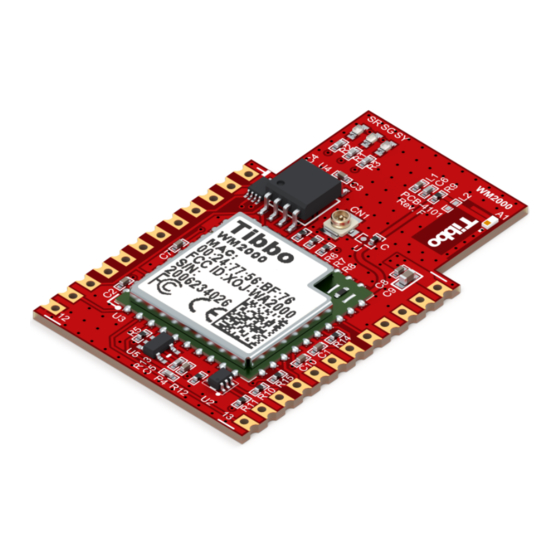
Ordering Info and Specifications WM2000 devices are supplied with an onboard chip antenna and a U.FL connector for attaching an external antenna. The module carries a... - Page 39 Fully functional, associated: ~120mA Occasional bursts of up to ~500mA Backup power voltage 1.8V - 3.3V range (VCCB pin) Backup current (VCCB pin) 30µA ±15% when the WM2000 is not powered (0V on VCC) Operating temperature -40°C to +85°C Operating relative 10-90% humidity ©...
-
Page 40: Em2000 Basic/C-Programmable Iot Module
Think the above table should contain additional data? Do not just assume that you know the answer — talk to Tibbo! Remember that the ultimate responsibility for all decisions you make regarding the use and the mode of use of Tibbo products lies with you, our customer. - Page 41 1MB total for TiOS, code, and file system). · 56 I/O lines (vs. 54 lines on the EM1000). · 4-channel ADC. · The ability to update TiOS firmware and compiled Tibbo BASIC/C app over-the-air (this requires the WA2000 and an iOS or Android device). Hardware features ·...
- Page 42 Ethernet LAN; oR o Over-the-air (this requires the WA2000 and an iOS or Android device). · Tibbo BASIC/C application can be debugged through the Ethernet LAN (no additional debugging hardware is required). · CE- and FCC-certified. * Must be connected externally.
-
Page 43: Detailed Device Info
Note: "SPI connector" is now referred to as "wireless add-on port" See these topics for more information on various hardware facilities of the EM2000: · General-purpose I/O Lines · Wireless Add-on port, Wi-Fi Communications · Ethernet Port Lines · Serial Ports © Tibbo Technology Inc. - Page 44 General-purpose I/O line 5 (P0.5). (1,2) GPIO6/P0.6/DT General-purpose I/O line 6 (P0.6). GPIO7/P0.7/DT General-purpose I/O line 7 (P0.7). (1,2) (1,2) GPIO8/P1.0 General-purpose I/O line 8 (P1.0); /RX0 RX, W1 input, and DATA input of the serial port 0. © Tibbo Technology Inc.
- Page 45 General-purpose I/O line 43 (does not belong to (1,2) any 8-bit port); ADC input System ground. GPIO44 General-purpose I/O line 44 (does not belong to (1,2) any 8-bit port). GPIO25/P3.1 General-purpose I/O line 25 (P3.1). (1,2) © Tibbo Technology Inc.
- Page 46 Backup power for the real-time counter; connect directly to the backup power source (1.8-3.3V range). DBGTX TX line of debug serial port. Positive power input, 3.3V nominal, +/- 5%, max. current consumption 100mA (100BaseT, full speed). © Tibbo Technology Inc.
-
Page 47: General-Purpose I/O Lines
Majority of those lines need to be correctly configured as inputs or outputs — this won't happen automatically. Several lines — such as TX and RX lines of the serial port when in the UART mode — are configured © Tibbo Technology Inc. -
Page 48: Wireless Add-On Port, Wi-Fi Communications
(or some other hardware block) is enabled. For details see "Platform-dependent Programming Information inside the EM2000 platform documentation (TIDE, TiOS, Tibbo BASIC, and Tibbo C Manual). Each I/O line has a weak pull-up resistor that prevents the line from floating when the output buffer is tri-stated. -
Page 49: Ethernet Port Lines
I/O lines can be used for communicating with it. This is facilitated by several I/O mapping properties offered by the Wi-Fi (wln.) object. For more details on Wi-Fi communications see wln. object's documentation in the TIDE, TiOS, Tibbo BASIC, and Tibbo C Manual. Ethernet Port Lines 4.2.1.3 The Ethernet port of the EM2000 is of the 100/10BaseT type. -
Page 50: Serial Ports
AVCC pins on the EM1000 are left unconnected on the EM2000 product (so it is OK if your board has these lines). Serial Ports 4.2.1.4 The EM2000 has four serial ports that can work in one of the three modes: UART, Wiegand, or clock/data. © Tibbo Technology Inc. - Page 51 DTR and DSR lines often found on RS232 ports are not controlled by the ser. object. It is the responsibility of your Tibbo BASIC/C application to take care of these lines. Therefore, you can choose what GPIO lines of the EM2000 will be used as DTR and DSR lines in your system.
-
Page 52: Wiegand And Clock/Data Circuit Examples
No additional circuitry is required to handle clock/data streams. For more information see the documentation for the serial (ser.) object found inside the TIDE, TiOS, Tibbo BASIC, and Tibbo C Manual. Wiegand and Clock/Data Circuit Examples In the Wiegand mode, the W0&1in input of the serial port must receive a logical AND of W0 and W1 output of attached Wiegand device. -
Page 53: Analog-To-Digital Converter (Adc)
The square wave generator can produce a square wave output on pin GPIO45/CO of the EM2000. This output is primarily intended for generating audio signals using buzzer and is covered in the beep (beep.) object — see the TIDE, TiOS, Tibbo BASIC, and Tibbo C Manual. -
Page 54: Real-Time Clock (Rtc)
Prolonging and Estimating EEPROM Life. Like all other flash memory devices on the market, flash ICs used in Tibbo products only allow for a limited number of write cycles. As the Wikipedia article on flash memory (https://en.wikipedia.org/wiki/Flash_memory) explains, modern flash ICs still suffer from comparatively low write endurance. -
Page 55: Led Lines
Status LEDs. Your Tibbo BASIC/C application can control red and green status LEDs, as well as up to four externally connected LED pairs through the pattern (pat.) object, which is documented in the TIDE, TiOS, Tibbo BASIC, and Tibbo C Manual. -
Page 56: External Keypad Support
To build a keypad you will need to have at least one return line. A sensible count of scan lines, however, starts from two! Having a single scan line is like having no scan lines whatsoever — you might just as well ground this single scan line, i.e. always keep it active: © Tibbo Technology Inc. - Page 57 Binary keypads (i.e. "keypads that output binary key codes") do not require scanning — they contain a (typically microcontroller-based) circuit that performs the scanning and outputs encoded binary codes of pressed keys. Such keypads are sometimes called "encoded keypads": © Tibbo Technology Inc.
-
Page 58: Power, Reset, Pll Control, And Mode Selection
For correct device operation, the VCCB line should not be left unconnected. You may connect this line to the backup battery, or main 3.3V power (see Real-time Counter). © Tibbo Technology Inc. -
Page 59: Mechanical Dimensions
· Low speed: 16MHz The clock speed can be changed programmatically, via the system (sys.) object. For more information see TIDE, TiOS, Tibbo BASIC, and Tibbo C Manual. Mode selection The function of the MD line is described in Setup Button (MD line). - Page 60 Additional height added by the supercapacitor ("-S" option devices only) Lead length Pin pitch Dimensions are for reference only. Tibbo assumes no responsibility for any errors in this Manual, and does not make any commitment to update the information contained herein.
-
Page 61: Ordering Info And Specifications
"A" and "T" versions are not standard and cannot be ordered from our online store. Contact Tibbo if you wish to order EM2000 devices with "A" or "T" options. If the flash memory size is omitted, 1024K option is implied. - Page 62 Think the above table should contain additional data? Do not just assume that you know the answer — talk to Tibbo! Remember that the ultimate responsibility for all decisions you make regarding the use and the mode of use of Tibbo products lies with you, our Customer.
-
Page 63: Em1000 Basic/C-Programmable Ethernet Module
2.54mm (0.1). The EM1000 is fully supported by TIDE software and a dedicated EM1000 platform that covers all hardware facilities of the module (see TIDE, TiOS, Tibbo BASIC, and Tibbo C Manual). For convenient testing and evaluation Tibbo offers... - Page 64 Prototyping-friendly 2.54mm (100mil) pin pitch. · Operating temperature range: -40 ~ +70 C. · Firmware and compiled Tibbo BASIC/C app can be updated through the serial port or Ethernet LAN. · Tibbo BASIC/C application can be debugged through the Ethernet LAN (no additional debugging hardware is required).
-
Page 65: Em1000-00 And -01
Small hardware changes were made to the EM1000 since its first release. Currently Tibbo supplies version "-01" of the module. The first version ever produced was "- 00". The main difference is in the Ethernet IC: the EM1000-...-00 used Davicom's DM9000 while the EM1000-...- 01 features newer DM9000A. -
Page 66: Detailed Device Info
Note: "SPI connector" is now referred to as "wireless add-on port" See these topics for more information on various hardware facilities of the EM1000: · General-purpose I/O Lines · Wireless Add-on port · Ethernet Port Lines © Tibbo Technology Inc. - Page 67 General-purpose I/O line 16 (P2.0); (1,2,3) interrupt line 0. GPIO17/P2.1/I General-purpose I/O line 17 (P2.1); (1,2,3) interrupt line 1. GPIO18/P2.2/I General-purpose I/O line 18 (P2.2); (1,2,3) interrupt line 2. GPIO19/P2.3/I General-purpose I/O line 19 (P2.3); (1,2,3) interrupt line 3. © Tibbo Technology Inc.
- Page 68 General-purpose I/O line 37 (P4.5). (1,2) GPIO36/P4.4 General-purpose I/O line 36 (P4.4). (1,2) GPIO39/P4.7 General-purpose I/O line 39 (P4.7). (1,2) GPIO38/P4.6 General-purpose I/O line 38 (P4.6). (1,2) Mode selection pin. <TEST PIN> Leave this pin unconnected. Reset line, active high. © Tibbo Technology Inc.
- Page 69 EM1000-...- 00: EM1000-...- 00: EM1000-...- 01: analog ground. EM1000-...- 01: AGND Ethernet port, positive line of the differential input signal pair. EM1000-...- 00: EM1000-...- 00: EM1000-...- 01: analog ground. EM1000-...- 01: AGND System ground. © Tibbo Technology Inc.
-
Page 70: General-Purpose I/O Lines
Majority of those lines need to be correctly configured as inputs or outputs — this won't happen automatically. Several lines — such as TX and RX lines of the serial port when in the UART mode — are configured © Tibbo Technology Inc. -
Page 71: Wireless Add-On Port
"landing" PCB area for the connector is left empty. Wireless add-on modules, such as the WA2000, may be soldered into the wireless add-on port pads on the EM1000. Tibbo will solder the WA2000 in if you order the "EM1000Nx" device. -
Page 72: Ethernet Port Lines
You can use either a standalone magnetics part (such as YCL-PH163112) or RJ45 connector with integrated magnetics (i.e. YCL-PTC1111-01G). Here are two connection diagrams based on the YCL-PTC1111-01G — one for the EM1000-...- 00, another one - for the EM1000-...- 01. © Tibbo Technology Inc. - Page 73 EM1000-...- 01 (see diagram below): · Do not install four 50 Ohm resistors (they are crossed out on the diagram). · Connect a wire between pins 4 and 7 of the RJ45 connector (pin numbers are for YCL-PTC1111-01G). © Tibbo Technology Inc.
-
Page 74: Serial Ports
The EM1000 has four serial ports that can work in one of the three modes: UART, Wiegand, or clock/data. All three modes are described in detail in the documentation for the serial (ser.) object found inside the TIDE, TiOS, Tibbo BASIC, and Tibbo C Manual. Additionally, see the Platform-dependent Programming Information section inside the EM1000 platform documentation (same manual). -
Page 75: Square Wave Generator
The square wave generator can produce a square wave output on pin GPIO45/CO of the EM1000. This output is primarily intended for generating audio signals using buzzer and is covered in the beep (beep.) object — see the TIDE, TiOS, Tibbo BASIC, and Tibbo C Manual. - Page 76 2.2V. Make sure that the voltage on this pin does not exceed 3.3V. Failure to observe this limit may cause permanent damage to the EM1000. Your Tibbo BASIC/C application can access the RTC through the RTC (rtc.) object, which is documented in the TIDE, TiOS, Tibbo BASIC, and Tibbo C Manual.
-
Page 77: Led Lines
Status LEDs. Your Tibbo BASIC/C application can control red and green status LEDs, as well as up to four externally connected LED pairs through the pattern (pat.) object, which is documented in the TIDE, TiOS, Tibbo BASIC, and Tibbo C Manual. - Page 78 The Tibbo BASIC/C application can check the current PLL mode through the system (sys.) object (see TIDE, TiOS, Tibbo BASIC, and Tibbo C Manual). If the PLL mode needs to be changed, the application can set new mode and then perform an internal reset (again, through the system object).
-
Page 79: Mechanical Dimensions
Finally, option "-T" devices have a female wireless add-on port connector, which the WA2000 can be plugged into. EM1000 modules of "-T" variety (cross-section D) are intended for convenient testing of the WA2000 and are not recommended for use in production devices. Module length Module width © Tibbo Technology Inc. -
Page 80: Ordering Info And Specifications
Device numbering scheme is as follows: "A" and "T" versions are not standard and cannot be ordered from our online store. Contact Tibbo if you wish to order EM1000 devices with "A" or "T" options. 512K devices are no longer available. - Page 81 Clock frequency 88.4736MHz with PLL on 512KBytes or 1024KBytes, the entire memory minus Flash memory 64KB is available for storing Tibbo BASIC/C application and data. Typical write endurance is 100'000 write cycles per 256-byte sector. See the warning in Flash and EEPROM Memory.
- Page 82 Think the above table should contain additional data? Do not just assume that you know the answer — talk to Tibbo! Remember that the ultimate responsibility for all decisions you make regarding the use and the mode of use of Tibbo products lies with you, our Customer.
-
Page 83: Em1206 Basic/C-Programmable Ethernet Module
The EM1206 is fully supported by TIDE software and a dedicated EM1206 platform that covers all hardware facilities of the module (see TIDE, TiOS, Tibbo BASIC, and Tibbo C Manual). For convenient testing and evaluation Tibbo offers the EM1206EV evaluation board. - Page 84 (LxWxH): 34.4 x 20.0 x 15.5mm. · Operating temperature range: -40 ~ +70 C. · Firmware and compiled Tibbo BASIC/C app can be updated through the serial port or Ethernet LAN. · Tibbo BASIC/C application can be debugged through the Ethernet LAN (no additional debugging hardware is required).
-
Page 85: Detailed Device Info
Depending on the EM1206 version, magnetics connector can be soldered facing up or down, as described in the Mechanical Dimensions topic. See these topics for more information on various hardware facilities of the EM1206: © Tibbo Technology Inc. - Page 86 General-purpose I/O line 2 (P0.2); (1,2,3) 1/INT2 RX, W1, din input of the serial port 1; Interrupt line 2. GPIO3/P0.3/TX General-purpose I/O line 3 (P0.3); (1,2,3) 1/INT3 TX, W1, dout output of the serial port 1; Interrupt line 3. Notes: © Tibbo Technology Inc.
- Page 87 Ethernet port, positive line of the differential input signal pair. Ethernet port, negative line of the differential input signal pair. AVCC "Clean" 1.8V power output for magnetics circuitry. Analog ground. AGND Ethernet port, positive line of the differential output signal pair. © Tibbo Technology Inc.
-
Page 88: General-Purpose I/O Lines
Each I/O line has a weak pull-up resistor that prevents the line from floating when the output buffer is tri-stated. I/O line control is described in the io. object documentation (TIDE, TiOS, Tibbo BASIC, and Tibbo C Manual). Many I/O lines of the EM1206 have alternative functions and serve as inputs or... -
Page 89: Ethernet Port Lines
The EM1206 has four serial ports that can work in one of the three modes: UART, Wiegand, or clock/data. All three modes are described in detail in the ser. object documentation (TIDE, TiOS, Tibbo BASIC, and Tibbo C Manual). Additionally, see the Platform-dependent Programming Information section inside the EM1206 platform documentation (same manual). -
Page 90: Square Wave Generator
The rest of this flash memory is available to your Tibbo BASIC/C application and its data. Whatever memory space is left after the compiled application is loaded can be used as a flash disk (see fd. -
Page 91: Led Lines
Therefore, your battery-based backup circuit should be designed in a way that does not drain the battery while the Vcc is applied. Your Tibbo BASIC/C application can access the RTC through the rtc. object (see TIDE, TiOS, Tibbo BASIC, and Tibbo C Manual). -
Page 92: Power, Reset, And Mode Selection Lines
Unlike the EM1000, the EM12062 does not have a hardware pin to control the state of the PLL. On power up, the PLL is always enabled. Your Tibbo BASIC/C application can change the PLL mode programmatically. The application can check the current PLL mode through the sys. -
Page 93: Onboard Leds
Embedded Modules Power supply circuit Many power supply circuits will work well. The one below is being used by Tibbo. The circuit can handle input voltages in the 9-24V range. Notes: · U1 (AP1501-33) is a popular power IC manufactured by Anachip (now Diodes Incorporated, www.diodes.com) -
Page 94: Thermal Considerations
PCB and in contact with the heat-conductive sticker. Best results are achieved when the copper area is larger, and also when two copper areas are provided on both sides of the host PCB and interconnected by a number of large vias. © Tibbo Technology Inc. -
Page 95: Mechanical Dimensions
Embedded Modules Mechanical Dimensions Length Width © Tibbo Technology Inc. - Page 96 Distance from the edge of the board to the pins of the main connector Distance from the edge of the board to the pins of the magnetics connector Distance from the edge of the board to the pins of the additional connector Connector pin length © Tibbo Technology Inc.
-
Page 97: Ordering Info And Specifications
Embedded Modules All dimensions are in millimeters. Dimensions are for reference only. Tibbo assumes no responsibility for any errors in this Manual, and does not make any commitment to update the information contained herein. Ordering Info and Specifications Device numbering scheme is as follows: 512K devices are no longer available. - Page 98 11.0592MHz with PLL off Clock frequency 88.4736MHz with PLL on 1024KBytes, entire memory minus 64KB is available Flash memory to store Tibbo BASIC/C application and data. Typical write endurance is 100'000 write cycles per 256-byte sector. See the warning in Flash and EEPROM Memory.
-
Page 99: Em510 "Minimo" Basic/C-Programmable Iot Module
Think the above table should contain additional data? Do not just assume that you know the answer — talk to Tibbo! Remember that the ultimate responsibility for all decisions you make regarding the use and the mode of use of Tibbo products lies with you, our Customer. - Page 100 WA2000 add-on). · SSI (SPI and I2C communications) object included. · The ability to update TiOS firmware and compiled Tibbo BASIC/C app over-the-air (this requires the WA2000 and an iOS or Android device). · C lower internal running temperature (52 C vs.
- Page 101 Over-the-air (this requires the WA2000 and an iOS or Android device). · Tibbo BASIC/C application can be debugged through the Ethernet LAN (no additional debugging hardware is required). · CE- and FCC-certified. * The EM510 does not support the combination of 7 bits/character mode and the "none"...
-
Page 102: Detailed Device Info
1; This pin is also used for interfacing to the external flash. GPIO2/P0.2 General-purpose I/O line 2 (P0.2). GPIO3/P0.3 General-purpose I/O line 3 (P0.3); This pin is also used for interfacing to the external flash. © Tibbo Technology Inc. -
Page 103: Serial Port And General-Purpose I/O Lines
The EM510 has ten I/O lines: eight general-purpose I/O lines GPIO0-7, plus TX and RX lines of the serial port. I/O lines of the EM510 are NOT 5V-tolerant. The maximum load current for each line is 10mA. © Tibbo Technology Inc. - Page 104 TiOS and your application should not attempt to manipulate these lines at the same time. The fd. object is enabled in the Project Settings dialog of Tibbo IDE software. To enable, click on the Customize button (of the Project Settings dialog) and set "Flash disk (fd.) object"...
-
Page 105: Ethernet Port Lines
Tibbo Devices. For more information on fd., bt., ser., io., and other objects, see the TIDE, TiOS, Tibbo BASIC, and Tibbo C Manual. Additionally, see the Platform-dependent Programming Information section inside the EM510 platform documentation (same manual). Ethernet Port Lines 4.5.1.2... -
Page 106: Flash And Eeprom Memory
For more information see Prolonging and Estimating EEPROM Life. Like all other flash memory devices on the market, flash ICs used in Tibbo products only allow for a limited number of write cycles. As the Wikipedia article on flash © Tibbo Technology Inc. -
Page 107: Led Lines
The maximum load for each line is 10mA. For a small LED, a 330 Ohm series resistor will provide sufficient brightness. The SG and SR lines are used to control two status LEDs found on Tibbo products. These LEDs can show various flashing patterns indicating the current device state... -
Page 108: Power, Reset, And Mode Selection Lines
The function of the MD line is described in Setup Button (MD line). Power supply circuit Many power supply circuits will work well. The one below is being used by Tibbo. This circuit can handle input voltages in the 9-24V range. Notes: ·... -
Page 109: Mechanical Dimensions
Embedded Modules Mechanical Dimensions Module height Module width Module thickness Lead length Pin pitch Module footprint dimension © Tibbo Technology Inc. -
Page 110: Ordering Info And Specifications
Programmable Hardware Manual (PHM) Module footprint dimension Module footprint dimension Dimensions are for reference only. Tibbo assumes no responsibility for any errors in this Manual, and does not make any commitment to update the information contained herein. Ordering Info and Specifications The EM510 "MiniMo"... -
Page 111: Em500 "Minimo" Basic/C-Programmable Ethernet Module
Think the above table should contain additional data? Do not just assume that you know the answer — talk to Tibbo! Remember that the ultimate responsibility for all decisions you make regarding the use and the mode of use of Tibbo products lies with you, our Customer. - Page 112 The EM500 is fully supported by TIDE software and a dedicated EM500 platform that covers all hardware facilities of the module (see TIDE, TiOS, Tibbo BASIC, and Tibbo C Manual). For convenient testing and evaluation Tibbo offers the EM500EV development system.
- Page 113 Embedded Modules · Firmware and compiled Tibbo BASIC/C app can be updated through the serial port or Ethernet LAN. · Tibbo BASIC/C application can be debugged through the Ethernet LAN (no additional debugging hardware is required). · CE- and FCC-certified.
-
Page 114: Detailed Device Info
SI and SO of external flash. (1,2) GPIO2/P0.2 General-purpose I/O line 2 (P0.2). (1,2) GPIO3/P0.3 General-purpose I/O line 3 (P0.3); for flash disk operation, connect to CLK of external flash, also connect to 5.1K pull-up resistor to VCC (3.3V). © Tibbo Technology Inc. -
Page 115: Serial Port And General-Purpose I/O Lines
Serial Port and General-purpose I/O Lines 4.6.1.1 The EM500 has eight general-purpose I/O lines GPIO0-7 grouped into a single 8-bit GPIO port P0, plus one serial port. GPIO0 and GPIO1 lines double as interrupt inputs INT0 and INT1. © Tibbo Technology Inc. -
Page 116: Ethernet Port Lines
TX, RX, CTS, and CTS lines have different names and functions in the Wiegand and clock/data modes. Serial port operation is described in detail in the documentation for the serial (ser.) object found inside the TIDE, TiOS, Tibbo BASIC, and Tibbo C Manual. Additionally, see the Platform-dependent Programming Information section inside the EM500 platform documentation (same manual). -
Page 117: Flash And Eeprom Memory
The rest of this flash memory is available to your Tibbo BASIC/C application. The internal flash memory cannot be used as a flash disk. The fd. object (see TIDE, TiOS, Tibbo BASIC, and Tibbo C Manual) requires an external flash IC. -
Page 118: Led Lines
Prolonging and Estimating EEPROM Life. Like all other flash memory devices on the market, flash ICs used in Tibbo products only allow for a limited number of write cycles. As the Wikipedia article on flash memory (https://en.wikipedia.org/wiki/Flash_memory) explains, modern flash ICs still suffer from comparatively low write endurance. -
Page 119: Power, Reset, And Mode Selection Lines
Embedded Modules The SG and SR lines are used to control two status LEDs found on Tibbo products. These LEDs can show various flashing patterns indicating the current device state (see Status LEDs). On the EM500, there is an added twist: the same pair of status LEDs also indicates the current Ethernet link status through LED brightness. - Page 120 The function of the MD line is described in Setup Button (MD line). Power supply circuit Many power supply circuits will work well. The one below is being used by Tibbo. This circuit can handle input voltages in the 9-24V range. Notes: ·...
-
Page 121: Mechanical Dimensions
Embedded Modules Mechanical Dimensions Module height Module width Module thickness Lead length © Tibbo Technology Inc. -
Page 122: Ordering Info And Specifications
Module footprint dimension Module footprint dimension Module footprint dimension Dimensions are for reference only. Tibbo assumes no responsibility for any errors in this Manual, and does not make any commitment to update the information contained herein. Ordering Info and Specifications The EM500 "MiniMo"* device is only available in a single configuration and can be... - Page 123 Think the above table should contain additional data? Do not just assume that you know the answer — talk to Tibbo! Remember that the ultimate responsibility for all decisions you make regarding the use and the mode of use of Tibbo products lies with you, our Customer.
-
Page 124: Em1202 Basic/C-Programmable Ethernet Module
The EM1202 is fully supported by TIDE software and a dedicated EM1202 platform that covers all hardware facilities of the module (see TIDE, TiOS, Tibbo BASIC, and Tibbo C Manual). For convenient testing and evaluation Tibbo offers EM1202EV evaluation board. - Page 125 Power: 230mA @ 3.3V (100BaseT mode, PLL on). · Dimensions: 17.1x19.1x14.6mm. · Firmware and compiled Tibbo BASIC/C app can be updated through the serial port or Ethernet LAN. · Tibbo BASIC/C application can be debugged through the network and no additional debugging hardware, such as in-circuit emulator, is required.
-
Page 126: Detailed Device Info
Power, Reset, and Mode Selection Lines I/O pin assignment Function Description (1,2) GPIO28 General-purpose I/O line 28 (does not belong to any 8-bit port). (1,2) GPIO27 General-purpose I/O line 27 (does not belong to any 8-bit port). © Tibbo Technology Inc. - Page 127 RX, W1, and din input of the serial port 1. GPIO18/P2.2/I General-purpose I/O line 18 (P2.2); (1,2,3) interrupt line 2. GPIO11/P1.3/ General-purpose I/O line 11 (P1.3); TX, W1, and dout output of the serial port 1. © Tibbo Technology Inc.
-
Page 128: General-Purpose I/O Lines
Simplified structure of one I/O line of the EM1202 is shown on the circuit diagram below. Each line has an independent output buffer control. When the EM1202 powers up all I/O lines have their output buffers tri-stated (in other words, all I/O © Tibbo Technology Inc. -
Page 129: Ethernet Port Lines
(or some other hardware block) is enabled. For details see Platform-dependent Programming Information inside the EM1202 platform documentation (TIDE, TiOS, Tibbo BASIC, and Tibbo C Manual). Each I/O line has a weak pull-up resistor that prevents the line from floating when the output buffer is tri-stated. -
Page 130: Serial Ports
The square wave generator can produce a square wave output on pin GPIO29/CO of the EM1202. This output is primarily intended for generating audio signals using buzzer and is covered in the beep (beep.) object — see the TIDE, TiOS, Tibbo BASIC, and Tibbo C Manual. -
Page 131: Led Lines
Embedded Modules The rest of this flash memory is available to your Tibbo BASIC/C application and its data. Whatever memory space is left after the compiled application is loaded can be used as a flash disk (see fd. object documentation in the TIDE, TiOS, Tibbo BASIC, and Tibbo C Manual). -
Page 132: Power, Reset, And Mode Selection Lines
PLL mode through the system (sys.) object (see TIDE, TiOS, Tibbo BASIC, and Tibbo C Manual). If the PLL mode needs to be changed, the application can set new mode and then perform an internal reset (again, through the system object). The internal reset is identical to the power-on or external reset with one difference: the PLL mode will not default to "PLL on"... - Page 133 Ideally, one should use an oscilloscope to see what sort of "square wave" the power supply generates, both at low and high input voltages, as well as light and heavy loads. There are no recipes here — just try and see what works for your circuit. © Tibbo Technology Inc.
-
Page 134: Mechanical Dimensions
Module height (option without supercapacitor) 2.5 Lead length Pin pitch Dimensions are for reference only. Tibbo assumes no responsibility for any errors in this Manual, and does not make any commitment to update the information contained herein. © Tibbo Technology Inc. -
Page 135: Ordering Info And Specifications
Clock frequency 88.4736MHz with PLL on 512KBytes or 1024KBytes, entire memory minus Flash memory 64KB is available to store Tibbo BASIC/C application and data. Typical write endurance is 100'000 write cycles per 256-byte sector. See the warning in Flash and EEPROM Memory. -
Page 136: Em200
Think the above table should contain additional data? Do not just assume that you know the answer — talk to Tibbo! Remember that the ultimate responsibility for all decisions you make regarding the use and the mode of use of Tibbo products lies with you, our Customer. - Page 137 "platform" that defines EM200 capabilities from the programming point of view. The EM200 platform, along with the Tibbo BASIC/C language and TIDE software is described in the TIDE, TiOS, Tibbo BASIC, and Tibbo C Manual. Hardware features ·...
-
Page 138: Detailed Device Info
Serial Port and General-purpose I/O Lines · Flash and EEPROM Memory · LED Lines · Power, Reset, and Mode Selection Lines I/O pin assignment Function Description Green Ethernet status LED control line. Yellow Ethernet status LED control line. © Tibbo Technology Inc. - Page 139 GPIO5/RTS/W0 General-purpose I/O line 5; also RTS, W0, and out/cout cout output of the serial port. Green status LED control line. Red status LED control line. Reset line, active high. Mode selection pin. © Tibbo Technology Inc.
-
Page 140: Ethernet Port Lines
PTC1111-01G). Drawings below show circuit diagrams for both parts. Please, note the following: The Vout is an output that provides clean power for the magnetics circuitry, which is very sensitive to noise. On EM200C-02 devices, this pin outputs 3.3V; on EM200C-04 devices—1.8V. © Tibbo Technology Inc. -
Page 141: Serial Port And General-Purpose I/O Lines
The serial port of the EM200 can work in one of the three modes: UART, Wiegand, or clock/data. All three modes are described in detail in the documentation for the serial (ser.) object found inside the TIDE, TiOS, Tibbo BASIC, and Tibbo C Manual. Additionally, see the Platform-dependent Programming Information" section inside the EM200 platform documentation (same manual). -
Page 142: Flash And Eeprom Memory
The second half of the flash (64KB) is available to your Tibbo BASIC/C application. The EEPROM is almost fully available to your application, save for a small 8-byte area called "special configuration area". -
Page 143: Power, Reset, And Mode Selection Lines
The function of the MD line is described in Setup Button (MD line). Power supply circuit Many power supply circuits will work well. The one below is being used by Tibbo. The circuit can handle input voltages in the 9-30V range. Notes: ·... -
Page 144: Mechanical Dimensions
0.5 Lead "flash" Distance between lead rows Pin pitch Dimensions are for reference only. Tibbo assumes no responsibility for any errors in this Manual, and does not make any commitment to update the information contained herein. © Tibbo Technology Inc. -
Page 145: Ordering Info And Specifications
2048 bytes, 2040 bytes available to store application EEPROM memory data ICMP (ping) , and HTTP . Other Supported network protocols (such as DHCP) are implemented as Tibbo protocols BASIC/C functions. Number of simultaneous UDP or TCP (HTTP) connections Nominal power supply DC 5V, +/- 5% voltage (VCC pin) Max. -
Page 146: Boards
Think the above table should contain additional data? Do not just assume that you know the answer — talk to Tibbo! Remember that the ultimate responsibility for all decisions you make regarding the use and the mode of use of Tibbo products lies with you, our Customer. - Page 147 Boards The EM2001 is fully supported by TIDE software. The board shares the same programming platform with the EM2000 module (see TIDE, TiOS, Tibbo BASIC, and Tibbo C Manual). EM2001 advantages over the EM1001 board The EM2001 is a high-performance upgrade to our EM1001 board.
- Page 148 Ethernet LAN; or o Over-the-air (requires the WA2000 and an iOS or Android device). · Tibbo BASIC/C application can be uploaded and debugged through the Ethernet LAN (no additional debugging hardware is required). · CE- and FCC-certified. * Must be connected externally.
- Page 149 · Variable Types: Byte, char, integer (word), short, dword, long, real, string, plus user-defined arrays and structures. · Function groups: String functions, trigonometric functions, date/time conversion functions, encryption/hash calculation functions (AES, RC4, MD5, SHA-1), and more. © Tibbo Technology Inc.
-
Page 150: Detailed Device Info
· Analog-to-digital Converter (ADC) · I2C/SPI Support · Square Wave Generator · Flash and EEPROM Memory · Real-time Clock (RTC) and Backup Battery · LEDs and LED Lines · External LCD Support · External Keypad Support © Tibbo Technology Inc. - Page 151 (1,2) TX, W1 output, and DATA output of the serial port GPIO14/P1.6/R General-purpose I/O line 14 (P1.6); (1,2) RX, W1 input, and DATA input of the serial port 3. GPIO15/P1.7/T General-purpose I/O line 15 (P1.7); (1,2) © Tibbo Technology Inc.
- Page 152 (1,2) GPIO31/P3.7 General-purpose I/O line 31 (P3.7). (1,2) GPIO30/P3.6 General-purpose I/O line 30 (P3.6). (1,2) GPIO33/P4.1 General-purpose I/O line 33 (P4.1). (1,2) GPIO32/P4.0 General-purpose I/O line 32 (P4.0). (1,2) GPIO35/P4.3 General-purpose I/O line 35 (P4.3). (1,2) © Tibbo Technology Inc.
- Page 153 Leave this pin unconnected. GPIO52 Wireless add-on port, general-purpose I/O line 52 (1,2) (does not belong to any 8-bit port). GPIO53 Wireless add-on port, general-purpose I/O line 53 (1,2) (does not belong to any 8-bit port). © Tibbo Technology Inc.
-
Page 154: General-Purpose I/O Lines
(or some other hardware block) is enabled. For details see "Platform-dependent Programming Information inside the EM2000 platform documentation (TIDE, TiOS, Tibbo BASIC, and Tibbo C Manual). Each I/O line has a weak pull-up resistor that prevents the line from floating when the output buffer is tri-stated. -
Page 155: Wireless Add-On Port, Wi-Fi Communications
Nonetheless, it is always possible to connect the WA2000 by wires, in which case any combination of I/O lines can be used for communicating with it. For more details on Wi-Fi communications see TIDE, TiOS, Tibbo BASIC, and Tibbo C Manual (wln. object). -
Page 156: Serial Ports
DTR and DSR lines often found on RS232 ports are not controlled by the ser. object. It is the responsibility of your Tibbo BASIC/C application to take care of these lines. Therefore, you can choose what GPIO lines of the EM2000 will be used as DTR and DSR lines in your system. -
Page 157: Wiegand And Clock/Data Circuit Examples
No additional circuitry is required to handle clock/data streams. For more information see the documentation for the serial (ser.) object found inside the TIDE, TiOS, Tibbo BASIC, and Tibbo C Manual. Wiegand and Clock/Data Circuit Examples In the Wiegand mode, the W0&1in input of the serial port must receive a logical AND of W0 and W1 output of attached Wiegand device. -
Page 158: Analog-To-Digital Converter (Adc)
The square wave generator can produce a square wave output on pin GPIO45/CO of the EM2001. This output is primarily intended for generating audio signals using buzzer and is covered in the beep (beep.) object — see the TIDE, TiOS, Tibbo BASIC, and Tibbo C Manual. -
Page 159: Flash And Eeprom Memory
Prolonging and Estimating EEPROM Life. Like all other flash memory devices on the market, flash ICs used in Tibbo products only allow for a limited number of write cycles. As the Wikipedia article on flash memory (https://en.wikipedia.org/wiki/Flash_memory) explains, modern flash ICs still suffer from comparatively low write endurance. -
Page 160: External Lcd Support
LOW. Take this into consideration when designing the LED circuit. Your Tibbo BASIC/C application can control red and green status LEDs, as well as up to four externally connected LED pairs through the pattern (pat.) object, which is documented in the TIDE, TiOS, Tibbo BASIC, and Tibbo C Manual. - Page 161 To build a keypad you will need to have at least one return line. A sensible count of scan lines, however, starts from two! Having a single scan line is like having no scan lines whatsoever — you might just as well ground this single scan line, i.e. always keep it active: © Tibbo Technology Inc.
- Page 162 Binary keypads (i.e. "keypads that output binary key codes") do not require scanning — they contain a (typically microcontroller-based) circuit that performs the scanning and outputs encoded binary codes of pressed keys. Such keypads are sometimes called "encoded keypads": © Tibbo Technology Inc.
-
Page 163: Power, Reset, Pll Control, And Mode Selection
RST line of the EM2001. This will allow you to generate external resets. The RST line has active LOW polarity. If you are not using the RST line you can leave it unconnected. © Tibbo Technology Inc. -
Page 164: Mechanical Dimensions
· Low speed: 16MHz The clock speed can be changed programmatically, via the system (sys.) object. For more information see TIDE, TiOS, Tibbo BASIC, and Tibbo C Manual. Mode selection The function of the MD line is described in Setup Button (MD line). -
Page 165: Ordering Info And Specifications
Boards Dimensions are for reference only. Tibbo assumes no responsibility for any errors in this Manual, and does not make any commitment to update the information contained herein. Ordering Info and Specifications To order, use the "EM2001" ordering code. Hardware specifications... -
Page 166: Em1001 Basic/C-Programmable Iot Board
Think the above table should contain additional data? Do not just assume that you know the answer — talk to Tibbo! Remember that the ultimate responsibility for all decisions you make regarding the use and the mode of use of Tibbo products lies with you, our Customer. - Page 167 As such, the EM1001 is equally suited to low-volume production devices and hobbyist projects alike. The EM1001 is fully supported by TIDE software. The board shares the same platform with the EM1000 module (see TIDE, TiOS, Tibbo BASIC, and Tibbo C Manual). Hardware features ·...
- Page 168 Operating temperature range: -40 ~ +70 C. · Firmware is upgradeable through the serial port or network. · Tibbo BASIC/C application can be uploaded and debugged through the Ethernet LAN (no additional debugging hardware is required). · CE- and FCC-certified.
-
Page 169: Detailed Device Info
Wireless add-on port · Ethernet Port · Serial Ports · Square Wave Generator · Flash and EEPROM Memory · Real-time Counter · LED Lines · Power, Reset, PLL Control, and Mode Selection Lines I/O pin assignment © Tibbo Technology Inc. - Page 170 5. GPIO22/P2.6/I General-purpose I/O line 22 (P2.6); (1,2,3) interrupt line 6. GPIO23/P2.7/I General-purpose I/O line 23 (P2.7); (1,2,3) interrupt line 7. GPIO40 General-purpose I/O line 40 (does not belong to (1,2) any 8-bit port). © Tibbo Technology Inc.
- Page 171 LED. Maximum load on this line is 3mA. Use a buffer (logic gate) if higher current is desired. Green status LED control line. Also connected to the onboard LED. Maximum load on this line is © Tibbo Technology Inc.
- Page 172 General-purpose I/O line 52 (does not belong to (1,2,4) any 8-bit port). GPIO53 General-purpose I/O line 53 (does not belong to (1,2,4) any 8-bit port). Notes: 1. This line is 5V-tolerant and can be interfaced to 5V CMOS devices directly. © Tibbo Technology Inc.
-
Page 173: General-Purpose I/O Lines
(or some other hardware block) is enabled. For details see "Platform-dependent Programming Information inside the EM1000 platform documentation (TIDE, TiOS, Tibbo BASIC, and Tibbo C Manual). Each I/O line has a weak pull-up resistor that prevents the line from floating when the output buffer is tri-stated. -
Page 174: Ethernet Port
The square wave generator can produce a square wave output on pin GPIO45/CO of the EM1001. This output is primarily intended for generating audio signals using buzzer and is covered in the beep (beep.) object — see the TIDE, TiOS, Tibbo BASIC, and Tibbo C Manual. -
Page 175: Flash And Eeprom Memory
The rest of this flash memory is available to your Tibbo BASIC/C application and its data. Whatever memory space is left after the compiled application is loaded can be used as a flash disk (see fd. -
Page 176: Leds And Led Lines
LOW. Take this into consideration when designing the LED circuit. Your Tibbo BASIC/C application can control red and green status LEDs, as well as up to four externally connected LED pairs through the pattern (pat.) object, which is documented in the TIDE, TiOS, Tibbo BASIC, and Tibbo C Manual. - Page 177 The Tibbo BASIC/C application can check the current PLL mode through the system (sys.) object (see TIDE, TiOS, Tibbo BASIC, and Tibbo C Manual). If the PLL mode needs to be changed the application must set the desired new mode and then perform an internal reset (again, through the system object).
-
Page 178: Mechanical Dimensions
Use an open collector circuit to control the MD line as pressing the MD button short-circuits the line onto the GND. Mechanical Dimensions Dimensions are for reference only. Tibbo assumes no responsibility for any errors in this Manual, and does not make any commitment to update the information contained herein. -
Page 179: Ordering Info And Specifications
11.0592MHz with PLL off Clock frequency 88.4736MHz with PLL on 1024KBytes, the entire memory minus 64KB is Flash memory available for storing Tibbo BASIC/C application and data. Typical write endurance is 100'000 write cycles per 256-byte sector. See the warning in Flash and EEPROM Memory. -
Page 180: Nb10X0 And Ib100X Boards
Think the above table should contain additional data? Do not just assume that you know the answer — talk to Tibbo! Remember that the ultimate responsibility for all decisions you make regarding the use and the mode of use of Tibbo products lies with you, our Customer. - Page 181 Interface board implements all necessary I/O functionality. You can choose a standard board manufactured by Tibbo or create your own interface board containing just the right mix of I/O circuitry required for your project. The network board and the interface board are joined together by an IC1000 interboard cable.
-
Page 182: Nb10X0 Network Boards
Programmable Hardware Manual (PHM) Tibbo NB10x0 and IB100x boards can be used "as is" or with a stylish, industrial- grade housing — the DS10xx series industrial controllers are based on these boards as well. The NB1000 IB1000 bords are also used in the... -
Page 183: Nb1000 Connectors And Controls
APR-P0008 (APR-P0009, or APR-P0010) power adapter supplied by Tibbo or similar adapter. On the power jack, the ground is "on the outside", as shown on the figure below. Another way to connect power is through the power terminals located next to the power jack. -
Page 184: Ethernet Jack
1, thus making serial firmware upgrades possible. When the US jumper is closed, debug serial port is used. Reset button This button is connected to the RST pin of the EM1000. Pressing this button causes an "external" reset. © Tibbo Technology Inc. -
Page 185: External Led Control
LOW and this turns all LEDs ON. GPIO47 is a clock line- a positive (LOW-to-HIGH) transition on this line "shifts in" the data on the GPIO48 line. The circuit that controls the LEDs is shown below. LED numbers correspond to numbers shown on LB100x drawing. © Tibbo Technology Inc. -
Page 186: Buzzer
The buzzer of the NB1000 is connected to the GPIO45/CO line of the onboard EM1000. Your application can control the buzzer through the "beeper" (beep.) object (see TIDE, TiOS, Tibbo BASIC, and Tibbo C Manual). Recommended value for the beep.divider property is 21600. Ordering Info and Specifications... - Page 187 EM1000-1024K-S specification All specifications are subject to change without notice and are for reference only. Tibbo assumes no responsibility for any errors in this Manual, and does not make any commitment to update the information contained herein. © Tibbo Technology Inc.
-
Page 188: Nb1010 Board
LB1000 come assembled together and interconnected by the LC1000 cable. Additionally, the NB1010 comes with the IC1000 interboard cable. Therefore, you don't need to order the LB1000, LC1000, or IC1000 separately when purchasing the NB1010 board. © Tibbo Technology Inc. -
Page 189: Nb1010 Connectors And Controls
APR-P0008 (APR-P0009, or APR-P0010) power adapter supplied by Tibbo or similar adapter. On the power jack, the ground is "on the outside", as shown on the figure below. Another way to connect power is through the power terminals located next to the power jack. -
Page 190: Ethernet Jack
Interface boards typically implement serial port 1, thus making serial firmware upgrades possible. When the US jumper is closed, debug serial port is used. Reset button Pressing this button causes an "external" reset. Ethernet Status LEDs © Tibbo Technology Inc. -
Page 191: External Led Control
LED#1 (indicating the highest signal strength) is clocked in first. That's the short explanation. In further detail, we can say: · GPIO 48 is the Data line; set it to the state that you wish the LED to be in, LOW = ON, HIGH = OFF. © Tibbo Technology Inc. -
Page 192: Buzzer
The buzzer of the NB1010 is connected to the GPIO45/CO line. Your application can control the buzzer through the "beeper" (beep.) object (see TIDE, TiOS, Tibbo BASIC, and Tibbo C Manual). Recommended value for the beep.divider property is 21600. Optional Wi-Fi Interface... -
Page 193: Optional Gprs Interface
TiOS, Tibbo BASIC, and Tibbo C Manual). Before such data communications can take place, the Wi-Fi interface must be properly configured. This is jointly achieved by the wln. object and WLN library (again, see TIDE, TiOS, Tibbo BASIC, and Tibbo C Manual). -
Page 194: Ordering Info And Specifications
Device numbering scheme is as follows: All NB1010 boards are equipped with 1024KBytes of flash memory. NB1010 devices without "G", "C", or "GC" options are not being offered by Tibbo. If you want to purchase Ethernet-only board (without any wireless options), then... -
Page 195: Ib100X Interface Boards
Think the above table should contain additional data? Do not just assume that you know the answer — talk to Tibbo! Remember that the ultimate responsibility for all decisions you make regarding the use and the mode of use of Tibbo products lies with you, our Customer. -
Page 196: Ib1000, Ib1002, And Ib1003 (4 Serial Ports)
These boards can optionally be used with the TB1000 terminal block adapter. Connectors and Headers IB1000/2/3 boards carry two DB9-M connectors onboard. Two additional connectors attach (via cables) to two 2x5 pin headers located on the boards. © Tibbo Technology Inc. - Page 197 RX- (input) RX- (input) TX (output) TX+ (output) TX+ (output) DTR (output) TX- (output) TX- (output) SYSTEM GROUND SYSTEM GROUND SYSTEM GROUND DSR (input) RX+ (input) RX+ (input) RTS (output) RTS+ (output) CTS (input) CTS+ (input) © Tibbo Technology Inc.
-
Page 198: Serial Ports
NB10x0 network board). Tibbo BASIC/C application running on the EM1000 works with serial ports through a "serial" (ser.) object (see TIDE, TiOS, Tibbo BASIC, and Tibbo C Manual). The object takes care of the data transmission through the TX line as well as data reception through the RX line. - Page 199 IC1000 cable line RX (input) GPIO8/RX0 TX (output) GPIO9/TX0 CTS (input) GPIO16/CTS0 GPIO0/RTS0 (output) DSR (input) GPIO20/DSR0 GPIO4/DTR0 (output) HD/FD* GPIO32 RS_MODE* GPIO33 *IB1002 and IB1003 boards only Serial port 2 Line Corresponding EM1000 I/O IC1000 cable line © Tibbo Technology Inc.
- Page 200 (output) HD/FD* GPIO36 RS_MODE* GPIO37 *IB1002 and IB1003 boards only Serial port 4 Line Corresponding EM1000 I/O IC1000 cable line RX (input) GPIO14/RX3 TX (output) GPIO15/TX3 CTS (input) GPIO19/CTS3 GPIO3/RTS3 (output) DSR (input) GPIO23/DSR3 GPIO7/DTR3 (output) © Tibbo Technology Inc.
-
Page 201: Led Control
To turn the LED on, set the corresponding line LOW. Do not forget to configure LED control lines as outputs. This is done through the io.enabled property of the .io object (see TIDE, TiOS, Tibbo BASIC, and Tibbo C Manual). -
Page 202: Ib1004 And Sb1004 (Analog I/O)
Think the above table should contain additional data? Do not just assume that you know the answer — talk to Tibbo! Remember that the ultimate responsibility for all decisions you make regarding the use and the mode of use of Tibbo products lies with you, our Customer. -
Page 203: Terminal Blocks
There are nine terminals in each terminal block. · A/D inputs are grouped into terminal blocks 1 and 2. · D/A outputs are on terminal block 3. · Relay outputs and the serial port are on terminal block 4. © Tibbo Technology Inc. - Page 204 Function D/A channel 4, current output D/A channel 4, voltage output D/A channel 3, current output D/A channel 3, voltage output D/A channel 2, current output D/A channel 2, voltage output D/A channel 1, current output © Tibbo Technology Inc.
-
Page 205: Control Lines
Serial data in GPIO12 DO (output) Serial data out GPIO13 CLOCK Serial clock GPIO2 (output) (LOW idle state) Register selection: GPIO40 (output) HIGH - data register LOW - control register Receive frame sync GPIO32 (output) (Active LOW) © Tibbo Technology Inc. - Page 206 Relay 1 control: GPIO36 (output) HIGH (or input*) - relay off LOW - relay on RELAY2 Relay 2 control: GPIO37 (output) HIGH (or input*) - relay off LOW - relay on *GPIO line configured as input (default state) © Tibbo Technology Inc.
- Page 207 IC1000 cable line EM1000 I/O #8, red GPIO24 #7, green GPIO25 #6, red GPIO26 #5, green GPIO27 #4, red GPIO28 #3, green GPIO29 #2, red GPIO30 #1, green GPIO31 *GPIO line configured as input (default state) © Tibbo Technology Inc.
-
Page 208: Detailed Information
A/D channel 3, positive input (+) A/D channel 2, negative input (-) A/D channel 2, positive input (+) A/D channel 1, negative input (-) A/D channel 1, positive input (+) A/D GROUND (isolated from the rest of the device) © Tibbo Technology Inc. - Page 209 HIGH - data register LOW - control register Receive frame sync GPIO32 (output) (Active LOW) Transmit frame sync GPIO33 (output) (active LOW) CHS0 Channel selection, bit 0 GPIO41 (output) CHS1 Channel selection, bit 1 GPIO42 (output) © Tibbo Technology Inc.
- Page 210 (C/D is LOW), or data register that contains the conversion result (C/D is HIGH). The C/D line must remain stable (HIGH or LOW) for the entire duration of the transaction. Read and write "transactions" are illustrated on the diagram below. © Tibbo Technology Inc.
- Page 211 Set the CLOCK line LOW. This will conclude the first clock pulse. · Generate 23 additional clock pulses, every time setting the next bit on the DO line while the CLOCK is at LOW. · Set the TFS line HIGH. The write is complete. A/D converter initialization © Tibbo Technology Inc.
- Page 212 Once the TFS line goes HIGH marking the end of the write transaction, the DI line starts indicating the status of the converter. · The DI line will be HIGH while the converter is still busy. · The DI line will become LOW when the calibration is finished. © Tibbo Technology Inc.
- Page 213 The A/D converter is optically isolated from the rest of the device, so there are opto-couplers on all interface lines. Opto-couplers are relatively slow devices. This imposes a limit on how fast the clock line can be toggled. The minimum clock © Tibbo Technology Inc.
-
Page 214: D/A Converter
Function D/A channel 4, current output D/A channel 4, voltage output D/A channel 3, current output D/A channel 3, voltage output D/A channel 2, current output D/A channel 2, voltage output D/A channel 1, current output © Tibbo Technology Inc. - Page 215 Once all 16 bits have been clocked in, the negative pulse on the WR line sets new data and the new analog value appears on the outputs of the corresponding D/A channel (provided that the EN lines is at low). © Tibbo Technology Inc.
-
Page 216: Relays
Relay outputs Relay outputs are on terminal block #4. Both normally closed and normally opened lines are provided for each relay. Terminal # Function Relay 2, normally opened line Relay 2, normally closed line © Tibbo Technology Inc. -
Page 217: Rs232/485 Port
RS232 mode, the serial port can also be used to update the firmware of the EM1000 module located on the NB10x0 board. Port lines Serial port lines are on terminal block #4: Terminal # Function Relay 2, normally opened line Relay 2, normally closed line © Tibbo Technology Inc. -
Page 218: Led Control
To turn the LED on, set the corresponding line LOW. Remember to configure all LED control lines as outputs. For all LED control lines: HIGH (or input*) - LED off LOW - LED on © Tibbo Technology Inc. -
Page 219: Ordering Info And Specifications
76x85mm All specifications are subject to change without notice and are for reference only. Tibbo assumes no responsibility for any errors in this Manual, and does not make any commitment to update the information contained herein. © Tibbo Technology Inc. -
Page 220: Ib1005 And Sb1005 (Digital I/O)
Think the above table should contain additional data? Do not just assume that you know the answer — talk to Tibbo! Remember that the ultimate responsibility for all decisions you make regarding the use and the mode of use of Tibbo products lies with you, our Customer. -
Page 221: Terminal Blocks
3 and 4. Terminal block 1 Terminal # Function Sensors 3 and 4, positive line (+) Sensor 4, negative line (-) Sensor 3, negative line (-) Sensors 1 and 2, positive line (+) Sensor 2, negative line (-) © Tibbo Technology Inc. - Page 222 Relay 2, normally opened line Relay 2, common line Relay 1, normally closed line Relay 1, normally opened line Relay 1, common line Terminal block 4 Terminal # Function Relay 6, normally closed line Relay 6, normally opened line © Tibbo Technology Inc.
-
Page 223: Control Lines
Clock input for clock/data reader 2 I4 (input) Data line for input 4 GPIO12/ W1 input for Wiegand reader W1in2/ din2 Data input for clock/data reader 2. I5 (input) Data line for input 5 GPIO40 © Tibbo Technology Inc. - Page 224 RELAY5 Relay 5 control GPIO36 (output) RELAY6 Relay 6 control GPIO37 (output) *GPIO line configured as input (default state) RS232/485 port control For more information see RS232/485 port. Line Function Correspondi IC1000 cable line EM1000 I/O © Tibbo Technology Inc.
-
Page 225: Detailed Information
(both normally-opened and normally-closed terminals are provided). · RS232/485 port (RX/TX signals for the RS232, TX/RX+ and TX/RX- for the RS485). · Control lines for 8 LEDs on the LB1001 board (the board must be ordered separately). © Tibbo Technology Inc. -
Page 226: Opto-Isolated Inputs
Sensor 7, negative line (-) Sensor 6, positive line (+) Sensor 6, negative line (-) Sensor 5, positive line (+) Sensor 5, negative line (-) Vin (connected to the power input of the NB10x0) Working with inputs © Tibbo Technology Inc. - Page 227 The state of inputs is available on 8 general-purpose I/O (GPIO) lines of the EM1000 module (located on the NB10x0 network board). The EM1000 can check GPIO line state through the I/O (io.) object — see TIDE, TiOS, Tibbo BASIC, and Tibbo C Manual for details. Line Function Correspondi...
-
Page 228: Relays
Wiegand and clock/data streams so processing the reader data is very simple. More info can be found in the documentation for the "serial" (ser.) object (TIDE, TiOS, Tibbo BASIC, and Tibbo C Manual). As the serial object documentation explains, accepting Wiegand data requires additional logic circuit to be connected to the EM1000. -
Page 229: Rs232/485 Port
The serial port can be used, for instance, to connect to another IB100x board. In the RS232 mode, the serial port can also be used to update the firmware of the EM1000 module located on the NB10x0 board. © Tibbo Technology Inc. - Page 230 *GPIO line configured as input (default state) Do not forget to configure the TX, MODE, and DIR lines as outputs. A pull-down resistor on the MODE line ensures that the system boots up with the RS232 port selected. © Tibbo Technology Inc.
-
Page 231: Led Control
- channels 1-4: 2V-15V input range, can be used to connect card readers - channels 5-8: 5-50V input range Relays 6 relays, 30VDC/16A or 250VAC/15A Serial port lines RS232 mode: RX, TX RS485 mode: RX+/-, TX+/- © Tibbo Technology Inc. -
Page 232: Lb100X Led Boards
Think the above table should contain additional data? Do not just assume that you know the answer — talk to Tibbo! Remember that the ultimate responsibility for all decisions you make regarding the use and the mode of use of Tibbo products lies with you, our Customer. -
Page 233: Lb1001
"I/O" (io.) object found inside the TIDE, TiOS, Tibbo BASIC, and Tibbo C Manual. These LED's can also be used to play patterns generated by the ("pattern") .pat object. Correct "mapping" is required for this to work —... -
Page 234: Cable Data
The header type is 2x25, pitch=2.54mm. Connector pin assignment is shown below. The IC1000 length is approximately 40mm (as measured between the connectors). This cable is supplied with each NB10x0 board (but not with IB100x boards). © Tibbo Technology Inc. -
Page 235: Lc1000 Led Board Cable
"IB" boards. Connector pin assignment is shown below. LED numbers correspond to the numbers shown on the mechanical drawing of the LB100x. Pin #1 position of the connector is also shown on the drawing. Function Description © Tibbo Technology Inc. -
Page 236: Mechanical Data
50-pin header is on the right, while the LB1000 mounting holes are on the left. On the "NB" boards, the pin header is on the left, while the mounting holes are located on the right. © Tibbo Technology Inc. - Page 237 No-component zone width Aver. Mounting hole diameter Aver. Distance to the board mounting hole Aver. Distance to the board mounting hole Aver. 22.0 Distance to the LB100x mounting hole Aver. Distance to the LB100x mounting hole © Tibbo Technology Inc.
-
Page 238: Sb100X Board Dimensions
LB100x mounting hole dimension Aver. LB100x mounting hole, copper area diameter Dimensions are for reference only. Tibbo assumes no responsibility for any errors in this Manual, and does not make any commitment to update the information contained herein. SB100x Board Dimensions 5.3.5.2... - Page 239 No-component zone height Aver. Mounting hole diameter Aver. Distance to the board mounting hole Aver. Distance to the board mounting hole Max. 19.0 Header & interboard cable connector height Aver. 18.5 Gap between the IB100x and SB100x boards* © Tibbo Technology Inc.
-
Page 240: Lb100X Board Dimensions
* This is the standard gap; it will "happen" automatically when the boards are used inside the DS10xx housing. Dimensions are for reference only. Tibbo assumes no responsibility for any errors in this Manual, and does not make any commitment to update the information contained herein. LB100x Board Dimensions 5.3.5.3... - Page 241 Distance between LEDs m7 Aver. Distance from the board surface to the LED center m8 Max. LED height with respect to the board surface Aver. Gap between the LB100x and the bottom side of the NB10x0 (IB100x) © Tibbo Technology Inc.
-
Page 242: Ds1206N
(see below). The DS1206N is fully supported by TIDE software and a dedicated DS1206 platform that covers all hardware facilities of the board (see TIDE, TiOS, Tibbo BASIC, and Tibbo C Manual). This product ships preloaded with a fully functional serial-over-IP application. - Page 243 Superior upgrade to the EM1202EV board. · Based on a high-performance purpose-built 88MHz T1000 ASIC. · Powered by Tibbo OS (TiOS). · 10/100Base-T auto-MDIX Ethernet port (automatic detection of "straight" and "cross" cables). · Up to 3.5 serial channels: o DS1206N-RS: RS232 port (DB9M connector with optional software-controllable "12V"...
- Page 244 DS1206N-TS: direct 3.3V input (must be regulated to +/- 5%). · Board dimensions: 52.6x38.0mm. · Firmware and Tibbo BASIC/C application are upgradeable through the serial port or network. · Tibbo BASIC/C application can be debugged through the network and no additional debugging hardware, such as in-circuit emulator, is required.
-
Page 245: Ds1206N Hardware
APR-P0011, APR-P0012, or APR-P0013 power adapter supplied by Tibbo or similar adapter with 12V nominal output voltage. Adapter current rating should be at least 500mA. On the power jack, the ground is "on the outside", as shown on the figure below. -
Page 246: Ethernet Port
Tibbo BASIC/C application, enable (configure as output) line PL_IO_NUM8_PWROUT and then set this line to HIGH. Additional programming information can be found in TIDE, TiOS, Tibbo BASIC, and Tibbo C Manual (see i.o object and DS1206 platform documentation). -
Page 247: Multi-Channel Serial Port
Input from external device Power Power input/output Not used Ground Reset input, active low, use open collector driving circuit Setup line input, active low, use open collector driving circuit #6-12 Lines of TTL serial port, see mapping table below © Tibbo Technology Inc. - Page 248 For more information on serial ports and I/O lines of the DS1206N see ser. and io. object manuals (TIDE, TiOS, Tibbo BASIC, and Tibbo C Manual). Serial-over-IP application offered by Tibbo defines 15 "mapping options", or ways in which available I/O lines are utilized. These are presented in the table below:...
-
Page 249: Flash And Eeprom Memory
The rest of this flash memory is available to your Tibbo BASIC/C application and its data. Whatever memory space is left after the compiled application is loaded can be used as a flash disk (see fd. -
Page 250: Mechanical Dimensions
PCB outline dimension n7 Aver. 9.0 Horizontal distance between LEDs n8 Aver. 15.0 Distance from the vertical centerline of the PCB to the vertical centerline of the power jack (present on the DS1206N-RS and "-TM" only) © Tibbo Technology Inc. -
Page 251: Ordering Info And Specifications
"TS" version: TTL serial port on the pin header connector, direct 3.3V power input. "TM" and "TS" versions are not standard and cannot be ordered from our online store. Contact Tibbo if you wish to order DS1206B devices in "TM" or "TS" configurations. Examples of valid model numbers... - Page 252 Think the above table should contain additional data? Do not just assume that you know the answer — talk to Tibbo! Remember that the ultimate responsibility for all decisions you make regarding the use and the mode of use of Tibbo products lies with you, our Customer.
-
Page 253: Em1202Ev
The EM1202EV is fully supported by TIDE software and a dedicated DS1202 platform that covers all hardware facilities of the board (see TIDE, TiOS, Tibbo BASIC, and Tibbo C Manual). The EM1202 platform can be used with the board as well. This product ships preloaded with a fully functional serial-over-IP application. - Page 254 Hardware features · Based on the EM1202 BASIC-programmable embedded module. · Powered by Tibbo OS (TiOS). · 10/100BaseT auto-MDIX Ethernet port (automatic detection of "straight" and "cross" cables). · Up to 3.5 serial channels: o EM1202EV-RS: RS232 port (DB9M connector);...
-
Page 255: Em1202Ev Hardware
Boards · Firmware and Tibbo BASIC/C application are upgradeable through the serial port or network. · Tibbo BASIC/C application can be debugged through the network and no additional debugging hardware, such as in-circuit emulator, is required. · Also available as a DS1202 (EM1202EV-RS board with housing). -
Page 256: Power Arrangement
P0011, APR-P0012, or APR-P0013 power adapter supplied by Tibbo or similar adapter with 12V nominal output voltage. Adapter current rating should be at least 500mA. On the power jack, the ground is "on the outside", as shown on the figure below. -
Page 257: Multi-Channel Serial Port
CTS or DSR. The spare input cannot work as an RX line. This input is not used by the serial-over-IP application supplied by Tibbo and will be largely omitted from further discussion. Your Tibbo BASIC/C application can always use this extra input if you require it. - Page 258 3.3V Output to external device Input from external device *Not used in Tibbo serial-over-IP application. Your Tibbo BASIC/C program can use this line if needed. Serial-over-IP application offered by Tibbo defines 15 "mapping options", or ways in which available I/O lines are utilized ("spare" input is not used or shown). These...
-
Page 259: Additional Information On Serial Port Lines
This topic contains information related to programming of the EM1202EV. It assumes that you are familiar with Tibbo BASIC/C and the concept of "platforms". Everything you need to know regarding this can be found in TIDE, TiOS, Tibbo BASIC, and Tibbo C Manual. -
Page 260: Flash And Eeprom Memory
The rest of this flash memory is available to your Tibbo BASIC/C application and its data. Whatever memory space is left after the compiled application is loaded can be used as a flash disk (see fd. -
Page 261: Mechanical Dimensions
Av Horizontal distance between the mounting holes (first pair) m2 Av Horizontal distance between the mounting holes (second pair) m3 Av Distance from the front edge of the PCB to the first pair mounting holes © Tibbo Technology Inc. -
Page 262: Ordering Info And Specifications
2.0 TTL connector pin pitch (connector present on the EM1202EV-TM and "-TS" only) Dimensions are for reference only. Tibbo assumes no responsibility for any errors in this Manual, and does not make any commitment to update the information contained herein. - Page 263 "TS" version: TTL serial port on the pin header connector, direct 3.3V power input. "TM" and "TS" versions are not standard and cannot be ordered from our online store. Contact Tibbo if you wish to order DS1206B devices in "TM" or "TS" configurations. Examples of valid model numbers...
-
Page 264: Em1206Ev
Think the above table should contain additional data? Do not just assume that you know the answer — talk to Tibbo! Remember that the ultimate responsibility for all decisions you make regarding the use and the mode of use of Tibbo products lies with you, our Customer. -
Page 265: Wireless Add-On Connector
This connector is used to plug in an optional wireless add-on, such as the WA2000 Wi-Fi add-on, as well as other add-on modules that may be released by Tibbo in the future. The connector has 10 pins, as shown on the drawing below. Apart from the ground and Vcc (3.3V) lines, there are eight I/O lines that are connected directly to port 1... -
Page 266: Main And Backup Power
Use APR-P0011, APR-P0012, or APR-P0013 power adapter supplied by Tibbo or a similar adapter with 12V nominal output voltage. Adapter current rating should be at least 500mA. On the power jack, the ground is "on the outside", as shown on the figure below. -
Page 267: Multi-Channel Rs232 Port And Expansion Connector
EM1206EV, however, each line has a fixed direction defined by the RS232 transceiver IC. The IC used on the EM1206EV board implements three outputs and four inputs. Therefore, only seven I/O lines of the EM1206 are connected to the RS232 port of the EM1206EV board. © Tibbo Technology Inc. - Page 268 For more information on serial ports and I/O lines of the EM1206 see ser. and io. object manuals (TIDE, TiOS, Tibbo BASIC, and Tibbo C Manual). Serial-over-IP application offered by Tibbo defines 15 "mapping options", or ways to utilize the available I/O lines. These are presented in the table below:...
- Page 269 RX line. The TX line is "missing" because, once again, there are only three outputs available on the RS232 port. This is why this line is shown in grey lowercase (tx). This line, of course, is present and available on the expansion connector. © Tibbo Technology Inc.
-
Page 270: Em120/Em200Ev
Use APR-1014, APR-1015A, or APR-1018A power adapter supplied by Tibbo or similar adapter with 12V nominal output voltage. Adapter current rating should be at least 500mA. On the power jack, the ground is "on the outside", as shown on the figure below. -
Page 271: Ethernet Port Pin Assignment
<No connection> <No connection> <No connection> <No connection> RS232 Port Pin Assignment DB9M RS232 connector has the following pin assignment: <No connection> RX (input) TX (output) DTR (output) Ground DSR (input) RTS (output) CTS (input) <No connection> © Tibbo Technology Inc. -
Page 272: Expansion Connector Pin Assignment
RX pin on the expansion connector to supply a TTL RX signal from your own external board. Figure below illustrates this. Maximum load for all CMOS-type lines (P0, P1, ... RX, TX...) is 10mA. © Tibbo Technology Inc. -
Page 273: Development Systems
— the first chapter of our guided journey of exploration for the WM2000. Also included in the kit are a USB Type-C- to-A cable, a CR2032 button cell battery, and four jumpers installed in their default positions. The WM2000EV was designed to be completely self-contained and enable the exploration of the module's features without the need to wire in any external circuitry. - Page 274 In addition to hosting all the primary hardware, the WM2000EV's front plate features quick-response (QR) codes linking to CODY, Tibbo's project code wizard, and the L.U.I.S. (Loadable User Interface System) web app.
- Page 275 (Click here to open the image in a new window/tab) This diagram provides a more detailed look at how the evaluation board's components are wired to a seated WM2000. Lines have been grouped according to their use and color-coded for easier viewing. The line colors correspond with those of the block diagram.
-
Page 276: Getting Started
A blue LED (LPW) indicating if the power is applied to the board · Jumpers and test points: o For measuring the current of the WM2000 and the entire board o For enabling the low-power mode o For selecting the RTC power source (3.3V or backup battery) ·... - Page 277 RGB LED. The project demonstrates how easy it is to control the WM2000's PWM channels. It also shows the techniques for creating modern web interfaces — the LED can be controlled in real time and without page reloads.
-
Page 278: Wm2000Ev Demo #1 - Keen
In this chapter, you'll need to copy long strings of text from a website into the L.U.I.S. (Loadable User Interface System) app. To simplify this process, Tibbo strongly recommends that you use a single device for the entire tutorial. - Page 279 Projects in the menu under the Organizations drop-down menu to see the Add New button. 3. Give your project a name (for example, "WM2000") and click Add Project. 4. After creating your project, you will be on the Dashboards page.
- Page 280 L.U.I.S. app. 11. Then, locate and copy the Write 12. Paste the Write Key into the Key. corresponding field in the L.U.I.S. app. 13. Click Save to save the changes, then click Reboot. © Tibbo Technology Inc.
- Page 281 Projects drop- down box. 15. Under Analysis, select Median. 16. Under Event Stream, select sensors. 17. Under Target property, select either light or temperature. 18. Under Timeframe, change days to minutes. 19. Under Interval, select Minutely. © Tibbo Technology Inc.
-
Page 282: Wm2000Ev Demo #2 - Webpwm
Hint: For quick results, just put your fingers over the sensors. Your WM2000 will continue attempting to send data to Keen for as long as it is powered on and connected to your Wi-Fi network. The source code for this app is available on Github. Feel free to explore it, and even use it as the foundation for your own IIoT projects! WM2000EV Demo #2 —... - Page 283 Wi-Fi, but you will still need to use the Companion App to enable wireless debugging. The WM2000 can be forced to boot into APP0 — that is, the Companion App if this is what resides in your module's APP0 space — through the use of the MD button.
- Page 284 Programmable Hardware Manual (PHM) Uploading and using WebPWM app Now that you've configured the wireless interface on your WM2000, you can use TIDE to upload and debug applications, just like on Tibbo's "wired-first" programmable devices. In this chapter, we'll be uploading the WebPWM demo app...
-
Page 285: Wm2000Ev Demo #3 - Azure
Placing a sheet of regular white paper over the LED will diffuse its output, which will improve color rendition. Note #2: In this demo, the WM2000's PWM channels are only driving a single RGB LED, but you can use the same control method to drive a large number of LEDs; for example, an RGB LED strip. - Page 286 Programmable Hardware Manual (PHM) to receive and execute commands — such as activating the WM2000's onboard RGB LED. In this chapter, you'll need to copy long strings of text from a website into the L.U.I.S. (Loadable User Interface System) app. To simplify this process, Tibbo strongly recommends that you use a single device for the entire tutorial.
- Page 287 3. Click on the button labeled 4 at the bottom. Then click on Connect a device. 4. Select your WM2000 from the pop- up dialog and click Pair. 5. Click on Update Firmware From Local File. 6. In the dialog, find and select the azureiot_demo-wm2000.tcu file...
- Page 288 The following instructions assume that you will be setting up a new account. If you already have one, skip to step number 6. These instructions also assume that you have already configured your WM2000 to associate with a Wi-Fi network automatically and enabled wireless debugging. If...
- Page 289 When you're done, click Sign up. Note: Tibbo is not affiliated with Microsoft. We chose Azure for this demonstration because it is one of the world's largest cloud services...
- Page 290 For Location, you'll likely want to pick whichever choice is closest geographically to your deployment location. When you're done, click on Create. 10. At the "Your deployment is complete" screen, click on Go to resource. © Tibbo Technology Inc.
- Page 291 Development Systems 11. Click on IoT Central Application URL. 12. You will be at the dashboard for your application. Click on Device templates. 13. For the device type, select IoT Device and then click on Next: Customize. © Tibbo Technology Inc.
- Page 292 Programmable Hardware Manual (PHM) 14. Give the template a name. Do not check "This is a gateway device" and click Next: Review. 15. At the review screen, click on Create. © Tibbo Technology Inc.
- Page 293 Import a model. In the dialog, find and select the wm2000evm.json file included in the WM2000EV Project Repository and then click Open. 17. Leave the default settings included in the imported model. Click on Views. 18. Click on Generate default views. © Tibbo Technology Inc.
- Page 294 Click on Publish. 21. You will be presented with a summary of what will be published. Click on Publish. 22. In the left-hand menu, click on Devices. Then click on Create a device. © Tibbo Technology Inc.
- Page 295 Azure will result in continuous reboots. If you haven't already, Tibbo strongly recommends that you follow the BLE update process detailed in the previous section before you continue. 26. Power on your device and open the L.U.I.S. app...
- Page 296 32. Paste the string you copied into Primary key field to copy its value. the Primary key field. 33. Click on Save. 34. Click on Reboot. 35. Back in your Azure portal, click on Devices and then select your device. © Tibbo Technology Inc.
- Page 297 Controlling your WM2000 from Azure As we mentioned at the start of this tutorial, your WM2000 can receive and executive commands sent via Azure. The device template included with this demonstration is preconfigured to send a command to your module, which will turn on the WM2000EV's RGB LED in a pattern you determine.
- Page 298 RGB LED. This pattern has the same syntax as the pat.play method (see the TIDE, TiOS, Tibbo BASIC, and Tibbo C Manual), except that the "B" represents the color blue. © Tibbo Technology Inc.
-
Page 299: Wm2000Ev Demo #4 - Google Cloud Platform
WM2000EV Demo #4 — Google Cloud Platform 6.1.1.4 In the first chapter, we connected a WM2000 to a wireless network and securely transmitted data polled from the WM2000EV's integrated light and temperature sensors to the cloud. Next, we configured the WM2000 to associate with a Wi-Fi network automatically, enabled wireless debugging, loaded an application, and directly controlled the WM2000EV's onboard RGB LED via a web interface. - Page 300 Tibbo Updater smartphone app (available for and Android). 1. Place your WM2000 in the update mode's phase. The Monitor/Loader V4 Flowchart shows how to do this. Alternatively, follow this infographic that summarizes the steps: 2.
- Page 301 GCP Console and skip to step number 9. These instructions also assume that you have configured your WM2000 to associate with a Wi-Fi network automatically and enabled wireless debugging. If you need help doing so, please refer to the second chapter for guidance.
- Page 302 When you're done, click Start My Free Trial. Note: Tibbo is not affiliated with Google. We chose Google Cloud Platform for this demonstration because it is one of the world's...
- Page 303 Close to proceed. 9. In the left-hand navigation menu, hover over IAM & Admin. In the pop-out submenu, click Create a Project. 10. Give your project a name and then click Create. © Tibbo Technology Inc.
- Page 304 17. Next to the APIs & Services header, click Enable APIs and Services. 18. In the central search box, input Cloud Pub/Sub API and press enter. 19. Click on the result that reads: Cloud Pub/Sub API. © Tibbo Technology Inc.
- Page 305 24. Under the Cloud Pub/Sub topics header, click on the Select a Cloud Pub/Sub topic drop-down menu. Then, click Create a Topic. 25. Name your topic. Do not check any of the following checkboxes. Click Create Topic. © Tibbo Technology Inc.
- Page 306 Show Advanced Options. Under the Protocols header, make sure that MQTT and HTTP are checked. 27. Click Create. 28. In the left-hand navigation menu, click Devices. 29. Next to the Devices header, click Create a Device. © Tibbo Technology Inc.
- Page 307 -in ec_private.pem -pubout -out ec_public.pem. This generates the P-256 elliptic curve public key. 35. Finally, run this command: openssl req -x509 -new -key ec_private.pem -out ec_cert.pem -subj "/CN=unused". This generates the ES256 key with a self-signed X.509 certificate. © Tibbo Technology Inc.
- Page 308 Cloud Platform will result in continuous reboots. If you haven't already, Tibbo strongly recommends that you follow the BLE update process detailed in the Updating TiOS on your WM2000 section before you continue. 42. Power on your device and open the L.U.I.S. app...
- Page 309 L.U.I.S. 50. Paste the string you copied into the Registry ID field. 51. Set the Location ID field to match the location in Google Cloud Platform. 49. Copy your Registry ID. 52. Copy your Device ID. © Tibbo Technology Inc.
- Page 310 60. In the central search bar at the top of the screen, input Pub/Sub. Click Pub/Sub in the search results. 61. Click your Topic ID. 62. Under the Subscriptions tab at the bottom, click Create Subscription and then click Create subscription. © Tibbo Technology Inc.
- Page 311 Controlling your WM2000 from Google Cloud Platform As we mentioned at the start of this tutorial, your WM2000 can receive and execute commands sent via GCP. The demonstration application is preconfigured to receive...
- Page 312 WM2000EV's RGB LED will flash red, green, and blue before turning off. Feel free to experiment with other patterns. Note that if you don't end with "-" (dash), the LED will remain on at the last color in the pattern. © Tibbo Technology Inc.
-
Page 313: Em2000Ev
Development Systems EM2000EV The EM2000EV is a low-cost board for evaluating the EM2000 BASIC/C- programmable IoT Module (the module is not included with the board and must be purchased separately). The EM2000EV board incorporates the following: © Tibbo Technology Inc. -
Page 314: Em1000Ev
EY (Ethernet yellow) LED connected to the EY line of the EM2000. EM1000EV The EM1000-EV Evaluation System offers a convenient way of testing the EM1000 BASIC/C-programmable embedded module. The board features the following components: · Metal base. © Tibbo Technology Inc. -
Page 315: Em1000Tev
The EM1000-TEV development system has been designed to aid you in developing data terminals, data collection devices, and control equipment based on the EM1000 embedded module. Hence, the abbreviation: "TEV" stands for "terminal evaluation". The EM1000-TEV includes the following boards: © Tibbo Technology Inc. -
Page 316: Tev-Mb0
You can choose what display board will be installed on your EM1000-TEV. See Ordering Info for details. The EM1000-TEV is supplied with a sophisticated Tibbo BASIC/C "terminal" demo application that demonstrates the use of all hardware facilities of this development system. The application implements a hypothetical data collection terminal complete with onscreen setup menus, browser interface, event log, etc. -
Page 317: Tev-Kb0
The TEV-KB0 board carries 16 keys and 4 green LEDs. The keys are arranged as a 4x4 matrix, with 4 scan lines and 4 return lines. Each scan line additionally controls one green LED. Schematic diagram of the TEV-KP0 board can be found on Tibbo website. -
Page 318: Tev-Lbx Boards
Required initialization code in Tibbo BASIC/C application This section assumes that you are familiar with Tibbo BASIC/C and TIDE software. These are documented in the TIDE, TiOS, Tibbo BASIC, and Tibbo C Manual. For correct board operation, click Project-> Settings, and select "EM1000" or "EM1000G"... - Page 319 2x20- pin connector. Each two pins of the connector are combined together for better electrical contact. Therefore, the connector effectively has 20 lines. Pin # Function VIN (12V) 3.3V GPIO48* GPIO47* GPIO46* GPIO39/P4.7* © Tibbo Technology Inc.
-
Page 320: Tev-Lb0
The image displayed on the panel is not visible unless the backlight is turned on. Related datasheets, as well as the schematic diagram for the TEV-LB0 board can be found on Tibbo website. Interconnection between the EM1000 and the panel/ contrast control/ backlight control... - Page 321 Backlight control line. Required initialization code in Tibbo BASIC/C application This section assumes that you are familiar with Tibbo BASIC/C and TIDE software. These are documented in the TIDE, TiOS, Tibbo BASIC, and Tibbo C Manual. For correct panel operation, click Project-> Settings, and select "EM1000" or "EM1000G"...
-
Page 322: Tev-Lb1
The TEV-LB1 board carries a 128x96, 4-bit RITDISPLAY RGS13128096 OLED panel. This panel is based on a SOLOMON SSD1329 controller. Related datasheets, as well as the schematic diagram for the TEV-LB1 board can be found on Tibbo website. © Tibbo Technology Inc. - Page 323 Pin number on the TEV-LB1 connector. Required initialization code in Tibbo BASIC/C application This section assumes that you are familiar with Tibbo BASIC/C and TIDE software. These are documented in the TIDE, TiOS, Tibbo BASIC, and Tibbo C Manual. For correct panel operation, click Project-> Settings, and select "EM1000" or "EM1000G"...
-
Page 324: Tev-Lb2
The image displayed on the panel is not visible unless the backlight is turned on. Related datasheets, as well as the schematic diagram for the TEV-LB2 board can be found on Tibbo website. Interconnection between the EM1000 and the panel/ backlight control... - Page 325 Backlight control line. Required initialization code in Tibbo BASIC/C application This section assumes that you are familiar with Tibbo BASIC/C and TIDE software. These are documented in the TIDE, TiOS, Tibbo BASIC, and Tibbo C Manual. For correct panel operation, click Project-> Settings, and select "EM1000" or "EM1000G"...
-
Page 326: Tev-Ibx Boards
Programmable Hardware Manual (PHM) io.num=PL_IO_NUM_47 io.enabled=YES io.state=LOW TEV-IBx Boards The TEV-IBx are interface boards. Two boards are currently supplied by Tibbo: · TEV-IB0: RS232/422/485 serial port board (each EM1000-TEV system has two of them); · TEV-IB1: 3 x opto-input/ 3 x relay output board (each EM1000-TEV system has two of them). -
Page 327: Tev-Ib0
SP334 in different operating modes. Related datasheets, assembly program for the microcontroller, as well as the schematic diagram for the TEV-IB0 board can be found on Tibbo website. Two switches are provided on the board for protocol selection. Switch 1 selects between RS232 and RS422/485 signal levels. -
Page 328: Tev-Ib1
CTS- (input) Required initialization code in Tibbo BASIC/C application This section assumes that you are familiar with Tibbo BASIC/C and TIDE software. These are documented in the TIDE, TiOS, Tibbo BASIC, and Tibbo C Manual. Correct preset of serial ports falls outside the scope of this manual. This section will only remind you that you need to set a correct serial port mode matching the mode selected by the switches of the TEV-IB0. - Page 329 The GPIO line of the EM1000 will be LOW when the current is flowing through the input. Terminal block Function Terminal # Relay1, common Relay1, normally closed Relay1, normally opened Relay2, common © Tibbo Technology Inc.
-
Page 330: Ordering Info
Connecting a card reader Ability to handle a Wiegand or clock/data reader output is a unique feature of the serial ports of the EM1000. For more information, see TIDE, TiOS, Tibbo BASIC, and Tibbo C Manual ("Serial" (ser.) object documentation). - Page 331 "straight" Ethernet cable. Good for crossover connections as well, since the EM1000 supports Auto-MDIX. · WAS-P0005(B) serial cable. Can be used for firmware upgrades through the serial port. Additionally, any board or accessory from the EM1000-TEV system can be purchased separately. © Tibbo Technology Inc.
-
Page 332: Em500Ev/Em510Ev
1024KBytes of flash memory, and a limited RS232 interface (RX, TX, CTS, RTS). Tibbo offers a fully functional serial-over-IP application that can be tested on the EM500EV. Written in Tibbo BASIC, the application is compatible with Tibbo Device Server Toolkit software, comes with complete source code, and can be modified by the user. -
Page 333: Em500Ev-Mb0
(see below). · button, which is connected to the MD input of the EM500 (EM510). · Green and red status LEDs. · A two-row interface board connector. Interface board (IB) connector Pin # Function Vcc output (3.3V) © Tibbo Technology Inc. -
Page 334: Em500Ev-Ib0
SIPEX SP3243 RS232 transceiver IC. RS232 interface lines are available on a standard DB-9M connector: Pin # (DB- R232 line (DB- EM500 control line CD (input) GPIO4/P0.4 RX (input) TX (output) DTR (output) GPIO3/P0.3 © Tibbo Technology Inc. -
Page 335: Em500Ev-Ib1
Notice the orientation of the GA1000 module. The EM500EV-IB1 features a connector for the GA1000 Wi-Fi add-on module, 1024KBytes of flash memory, and a serial port with limited functionality (RX, TX, CTS, and RTS lines only). © Tibbo Technology Inc. - Page 336 Programmable Hardware Manual (PHM) Connection to the GA1000 is implemented according to the schematic diagram C presented in the Connecting GA1000 to Tibbo Devices topic. Note that the GA1000 is only supported by the EM500 module. Connection to the flash memory is implemented according to the schematic...
-
Page 337: Em500Ev-Ib2
1024KBytes of flash memory, and a serial port with limited functionality (RX, TX, CTS, and RTS lines only). Connection to the WA2000 is implemented according to the schematic diagram in Connecting WA2000 to Tibbo Devices topic. Note that the WA2000 is only supported by the EM510 module. -
Page 338: Ordering Info
Same as EM510EV-W, but with an EU type 12V power adapter included. EM510EV-W-U Same as EM510EV-W, but with a US type 12V power adapter included. EM500EV-i0 (Obsolete) EM500 development system, includes: · EM500EV-MB0 motherboard with the EM500 module on a socket. © Tibbo Technology Inc. -
Page 339: Tibbo Project System (Tps)
*** Because only the EM500 module works with the GA1000 add-on. If you wish to receive both the IB0 and IB1 boards, order the complete development system with one of the IB boards, and separately the second IB board separately. Tibbo Project System (TPS) © Tibbo Technology Inc. - Page 340 TPP + Tibbits [+ TPB] = Tibbo Project System (TPS) Combine a Tibbo Project PCB (TPP) with at least one Tibbit, and you get a Tibbo Project System (TPS). A TPS may or may not be housed in a Tibbo Project Box (TPB).
-
Page 341: Tps: The General View
Tibbo Project System (TPS) TPS: the General View Shown above is a typical Tibbo Project System in a housing (Tibbo Project Box). To be exact, the above image depicts a size 3 system. We also offer size 2 systems that are approximately half as wide. -
Page 342: Tibbit Form Factors & Colors
Project PCBs and fit in our Tibbo Project Box enclosures. Connector Tibbits actually form two walls of a Tibbo Project Box, as you can clearly see on the general view image. Tibbit Form Factors & Colors Tibbits are divided into Tibbit modules ("M" devices) and Tibbit connectors ("C"... -
Page 343: M1 "Narrow" Tibbits
Tibbo Project System (TPS) M1 "Narrow" Tibbits 7.2.1.1 M1 Tibbits are single-width modules occupying one "M" socket on the standard tile. Their footprint is roughly 7 x 14 "squares" (one "square" is 2.54 x 2.54 mm). M1 devices have four I/O lines for interfacing with the outside world. We found four to be the magic number. - Page 344 On Tibbo Project PCBs these pins are connected to the main CPU. Pins 2-5 are I/O lines facing the outside world. On Tibbo Project PCBs they go to Tibbit connector sockets (i.e. connect to devices).
-
Page 345: M2 "Wide" Tibbits
Tibbo Project System (TPS) M2 "Wide" Tibbits 7.2.1.2 M2 Tibbits are double-width modules occupying two "M" sockets on the standard tile. They are roughly 14 x 14 "squares" (one "square" is 2.54 x 2.54 mm). With double the size comes the doubled internal space and I/O capacity. M2s have eight I/O lines. - Page 346 Tibbo Project PCBs these pins are connected to the main CPU. Pins 2-5 and 8-11 are I/O lines facing the outside world. On Tibbo Project PCBs they go to Tibbit connector sockets (i.e. connect to devices). Pins 12 and 24 are the GROUND and +5V power pins. Most Tibbit Modules consume (take) 5V power.
-
Page 347: C1 "Narrow" Tibbits
Tibbo Project System (TPS) C1 "Narrow" Tibbits 7.2.1.3 C1 devices are single-width "connectors". They occupy one "C" socket on the standard tile and install alongside "M" Tibbits. C1s have the equal width and height with devices. Tibbit "connectors" have hooks that hold on to the host board's edge thus adding mechanical stability. -
Page 348: C2 "Wide" Tibbits
Tibbit "connectors" have hooks that hold on to the host board's edge thus adding mechanical stability. C2 Tibbits are always orange. C2s never have status LEDs. I/O pins C2 Tibbits have a single row of 11 pins: © Tibbo Technology Inc. - Page 349 Tibbo Project System (TPS) Pins 1-4 and 8-11 are I/O lines that connect directly to the I/O lines of adjacent "M" sockets. A single C2 may connect to one Tibbit or two Tibbits. Pin 5 is the +5V power pin. Most C2 devices only house connectors and do not require any power.
-
Page 350: H1 "Hybrid" Tibbits
H1 devices have no pins on their C1 "section": Pins on the M1 section have the standard positioning, except not all of the pins 1-5 may or may not be present. This is because the sections of hybrid devices are interconnected directly. © Tibbo Technology Inc. -
Page 351: H2 "Hybrid" Tibbits
Tibbo Project System (TPS) H2 "Hybrid" Tibbits 7.2.1.6 H2 Tibbits are merged devices. They occupy the combined space of one M2 and one C2 Tibbit. The H2 form factor is used when it is unsafe or undesirable to interconnect M2 and... -
Page 352: Tibbit Power Lines
For example, Tibbit takes DC input in the 9-18V range, while Tibbit implements PoE (power-over-Ethernet) power supply. Both take external power and convert it into +5V. Tibbit #12, however, generates +15/- 15V voltages form the 5V power rail. © Tibbo Technology Inc. -
Page 353: Tibbit Sockets And Tiles
As long as you follow electrical specifications for Tibbits you can use and interconnect them in any way you like. This manual teaches a structured approach based on Tibbit sockets and tiles. This is the approach used by the Tibbo Project System. -
Page 354: Electrical Connections On A Tile
Tibbits. GND, +5V, +15V, and -15V rails were already explained in Tibbit Power Lines. Eight control lines of the tile — four per "M" socket — go to the TPP's CPU. © Tibbo Technology Inc. -
Page 355: Tibbits With "Special Needs
Tibbo Project System (TPS) "C" sockets and "M" sockets are interconnected directly (see eight short black lines). A word on the naming of control lines. "M" sockets (these are (S5) and (S7) on the diagram above) have control lines A, B, C, and D. -
Page 356: [Int] Tibbits That Require An Interrupt Line
(Wiegand and clock/data reader port) must be wired to the interrupt line, or they won't be able to do their job. The INT line, when present on a Tibbit, is always mapped into the control line D: © Tibbo Technology Inc. -
Page 357: [Poe] Tibbits That Require Poe Power Lines
Tibbo Project System (TPS) TPP2 features six "M" sockets with interrupt lines, while the TPP3 has eight such sockets. [POE] Tibbits That Require PoE Power Lines 7.2.5.3 Tibbit implement PoE (power-over-Ethernet) power supplies. By definition, PoE power comes from the Ethernet cable. Therefore, PoE Tibbits must be wired in such a way as to receive PoE power input from the RJ45 jack. -
Page 358: [Aud] Tibbits That Require Audio Functionality
#02 can also be used with ("nine terminal blocks" device). Who knows — maybe this, and not the DB9, is what's need in your project! This is the main reason why Tibbits were split into "modules" and "connectors". © Tibbo Technology Inc. -
Page 359: C1 + M1
Tibbo Project System (TPS) C1 + M1 7.2.6.1 devices are interconnected by four interface lines: As was explained, C1 devices do not have dedicated ground and power lines. Sometimes, such lines are just not necessary. For example, Tibbit #27 (IR... -
Page 360: C2 + M2
Since C2 devices have ground pins, there is no need to waste one of the available eight interface lines, so all lines can be put to good use and this comes handy for Tibbit (RS232/422/485 port) that utilizes all eight lines. © Tibbo Technology Inc. -
Page 361: C2 + Two M1S
Tibbo Project System (TPS) C2 + Two M1s 7.2.6.3 Some devices can be connected to two Tibbits simultaneously. The most obvious example is "C" Tibbit (nine terminal blocks). This is a very generic Tibbit that mixes well with various "M" devices. For example, "M" Tibbits... -
Page 362: Two C1S + M2
Terms output and input should be interpreted with respect to the main CPU of the host board. Therefore, "in" means "from the outside world and into the board". "Out" means "from the board towards the outside world". © Tibbo Technology Inc. - Page 363 Tibbo Project System (TPS) As an example, consider Tibbit (DAC, shown above). This Tibbit is based on the MCP4728 IC from Microchip. It communicates with the main CPU via the I2C interface lines SCL and SDA. There are also two additional interface lines LDAC and BUSY.
-
Page 364: Labeling
Three isolated inputs, common (-) #04-3, M1S: Three isolated inputs, common (+) #04-4, M1S: Four opto-inputs, common ground #04-5, M1S: Two 24V isolated inputs #04-6, M1S: Three 24V isolated inputs, common (-) #04-7, M1S: Three 24V isolated inputs, common (+) © Tibbo Technology Inc. - Page 365 Tibbo Project System (TPS) #04-8, M1S: Four 24V opto-inputs, common ground #05, M1S: RS485 port #06, M2T: Two high-power relays #07, M1S: Two solid state relays #08, M1S: Wiegand and clock/data reader port [INT] #09, M1S: Low-power 5V supply, 12V input...
-
Page 366: M1S: Four Direct I/O Lines
#00-1, M1S: Four Direct I/O Lines 7.2.9.1 Function: Four directly exposed I/O lines of the microcontroller Form factor: Category: Blank module Special needs: --- Power requirements: 5V/20mA Mates with: #19, #20, (limited use) See also: #00-2, #00-3 © Tibbo Technology Inc. - Page 367 Tibbo Project System (TPS) Details Sometimes you just want to work with CPU I/O lines directly — no logic or circuitry in between. This Tibbit is (basically) four wires that connect its control lines to I/O lines. Complement it with terminal block Tibbit (nine terminal blocks) or (four terminal blocks) and you have four CPU lines "exposed"...
-
Page 368: M1S: Three Direct I/O Lines And Ground
Note that a CPU I/O line has the voltage swing from 0-3.3V when the line is enabled (io.enabled= 1- YES). The voltage may be close to 5V when the line is disabled (io.enabled= 0- NO). This is because the CPU has weak pull-up resistors connected to 5V. LEDs © Tibbo Technology Inc. -
Page 369: M1S: Two Direct I/O Lines, +5V Power, Ground
Tibbo Project System (TPS) Three yellow LEDs are connected to three control lines of the CPU (through buffering gates). LEDs light up for the LOW state of control lines. #00-3, M1S: Two Direct I/O Lines, +5V Power, Ground 7.2.9.3 Function: Two directly exposed I/O lines of the microcontroller plus the +5V... -
Page 370: 01, M1S: Four-Line Rs232 Port
#01, M1S: Four-line RS232 Port 7.2.9.4 Function: Simple RS232 port with only TX, RX, RTS, and CTS lines Form factor: Category: Input/output module Special needs: [SER], [INT] Power requirements: 5V/20mA Mates with: #19, #20, (limited use) See also: #02, © Tibbo Technology Inc. - Page 371 Tibbo Project System (TPS) Details This is a standard "simple" RS232 port. This Tibbit is based on a generic RS232 transceiver (we use Zywyn ZT232F). For "normal" RS232 applications, this Tibbit has to be connected to the TX and RX lines of the CPU's UART (see [SER]).
-
Page 372: 02, M2S: Rs232/422/485 Port
LOW state of control lines. #02, M2S: RS232/422/485 Port 7.2.9.5 Function: Universal RS232/422/485 port Form factor: Category: Input/output module Special needs: [SER], [INT]. Power requirements: 5V/40mA Mates with: #19, See also: #01, © Tibbo Technology Inc. - Page 373 Tibbo Project System (TPS) Details This is a "full" serial port that can be electronically programmed to work in RS232, RS422, or RS485 mode. The Tibbit is based on the Sipex SP337 universal transceiver. Mode selection is through FD/HD and 232/422-485 control lines:...
- Page 374 There are eight LEDs: five red and three green. Red LEDs are connected to TX, RTS, DTR, FD/-HD, and -232/422-485 lines. Green ones are for RX, CTS, and DSR. All LEDs are buffered (with logic gates) and light up for the LOW state of control lines. © Tibbo Technology Inc.
-
Page 375: M1S: Two Low-Power Relays (Configuration 1)
Tibbo Project System (TPS) #03-1, M1S: Two Low-power Relays (Configuration 1) 7.2.9.6 Function: Two mechanical low-power relays with independent normally opened terminals Form factor: Category: Output module Special needs: --- Power requirements: 5V/60mA (with both relays activated) Mates with: #19, #20,... -
Page 376: M1S: Two Low-Power Relays (Configuration 2)
(nine terminal blocks) or (four terminal blocks). LEDs There are two red LEDs which are connected to two relay control lines. LEDs light up for the LOW state of control lines (i.e. when relays are activated). © Tibbo Technology Inc. -
Page 377: M1S: Two Isolated Inputs
Tibbo Project System (TPS) #04-1, M1S: Two Isolated Inputs 7.2.9.8 Function: Two optically isolated inputs with independent terminals. Inputs are fully isolated from system ground. Form factor: Category: Input module Special needs: --- Power requirements: 5V/30mA Mates with: #19, #20,... -
Page 378: M1S: Three Isolated Inputs, Common (-)
(four terminal blocks). LEDs There are three green LEDs which are connected to three control lines. LEDs light up for the LOW state of control lines (i.e. when current passes through the diodes of the opto-couples). © Tibbo Technology Inc. -
Page 379: M1S: Three Isolated Inputs, Common (+)
Tibbo Project System (TPS) #04-3, M1S: Three Isolated Inputs, Common (+) 7.2.9.10 Function: Three optically isolated inputs with common (+). Inputs are fully isolated from system ground. Form factor: Category: Input module Special needs: --- Power requirements: 5V/35mA Mates with: #19, #20,... -
Page 380: M1S: Four Opto-Inputs, Common Ground
(four terminal blocks). LEDs There are four green LEDs which are connected to four control lines. LEDs light up for the LOW state of control lines (i.e. when current passes through the diodes of the opto-couples). © Tibbo Technology Inc. -
Page 381: M1S: Two 24V Isolated Inputs
Tibbo Project System (TPS) #04-5, M1S: Two 24V Isolated Inputs 7.2.9.12 Function: Two optically isolated inputs with independent terminals. Inputs are fully isolated from system ground. Form factor: Category: Input module Special needs: --- Power requirements: 5V/30mA Mates with: #19, #20,... -
Page 382: M1S: Three 24V Isolated Inputs, Common (-)
10mA, and this caps the maximum input voltage at around 30V. Add external resistors if you need to apply higher input voltage. Combine this Tibbit with terminal block devices — (nine terminal blocks) or (four terminal blocks). LEDs © Tibbo Technology Inc. -
Page 383: M1S: Three 24V Isolated Inputs, Common (+)
Tibbo Project System (TPS) There are three green LEDs which are connected to three control lines. LEDs light up for the LOW state of control lines (i.e. when current passes through the diodes of the opto-couples). #04-7, M1S: Three 24V Isolated Inputs, Common (+) 7.2.9.14... -
Page 384: M1S: Four 24V Isolated Inputs, Common Ground
Note that these are not "isolated inputs" — they share the ground line with the rest of your system. Still, the optical stage isolates your system from noise, ESD, spikes, and other external influences. Combine this Tibbit with terminal block devices — (nine terminal blocks) or (four terminal blocks). © Tibbo Technology Inc. -
Page 385: 05, M1S: Rs485 Port
PCB) and HIGH for output. For proper operation, the RTS line must be mapped and configured to be an output. This can be accomplished through the ser.rtsmap and io.enabled properties (see TIDE, TiOS, Tibbo BASIC, and Tibbo C Manual). © Tibbo Technology Inc. -
Page 386: 06, M2T: Two High-Power Relays
Function: Two mechanical high-power relays with normally opened and normally closed terminals Form factor: Category: Output module Special needs: --- Power requirements: 5V/140mA (with both relays activated) Mates with: #19, #20, See also: #03-1, #03-2, #07, #15, #58, © Tibbo Technology Inc. - Page 387 Tibbo Project System (TPS) Details These relays have the contact capacity rated at 16A/48V (resistive load). To activate a relay, set the corresponding control line LOW. When left unconnected, control lines default to HIGH (and, hence, relays are off). Combine this Tibbit with Tibbit (nine terminal blocks).
-
Page 388: 07, M1S: Two Solid State Relays
(nine terminal blocks) or (four terminal blocks). LEDs There are two red LEDs which are connected to two SSR control lines. LEDs light up for the LOW state of control lines (i.e. when relays are activated). © Tibbo Technology Inc. -
Page 389: 08, M1S: Wiegand And Clock/Data Reader Port
Tibbo Project System (TPS) #08, M1S: Wiegand and Clock/Data Reader Port 7.2.9.19 Function: Wiegand and clock/data reader port plus one open collector output Form factor: Category: Input/output module Special needs: [SER] Power requirements: 5V/20mA Mates with: #19, #20, (limited use) -
Page 390: 09, M1S: Low-Power 5V Supply, 12V Input
Function: Low-power non-isolated power supply with 5V output, 9-18V input range, shutdown control Form factor: Category: Power supply module Special needs: --- Power requirements: external 9-18V power Mates with: #18, #19, #20, See also: #10, #12, #23, #25, © Tibbo Technology Inc. -
Page 391: 10, M1T: Medium-Power 5V Supply, 12V Input
Tibbo Project System (TPS) Details This Tibbit is capable of generating up to 700mA of 5V power from the external input in the 9-18V range. Multiple power supply Tibbits can be used to increase available current or for power redundancy. -
Page 392: 11, M1S: Four Open Collector Outputs
The red LED is buffered (with a logic gate). #11, M1S: Four Open Collector Outputs 7.2.9.22 Function: Four open collector outputs Form factor: Category: Output module Special needs: [SER] (if reader emulation is desired) Power requirements: 5V/50mA Mates with: #19, #20, (limited use) © Tibbo Technology Inc. - Page 393 Tibbo Project System (TPS) See also: Details Transistors are rated for the maximum voltage of 24V and the maximum per- channel current of 0.5A. Note that the maximum current should not be exceeded even at lower voltages. Do not apply negative voltage! To open a transistor, set the corresponding control line LOW.
-
Page 394: 12, M1S: Low-Power +15/-15V Power Supply, 5V Input
+15V and -15V outputs results in 4.5mA of extra power drain on the 5V input. This 4.5 ratio is explained by the threefold difference in the input (5V) and output (15V) voltages, as well as associated power conversion losses. © Tibbo Technology Inc. -
Page 395: 13, M1S: Four-Channel Adc
Tibbo Project System (TPS) The module has a dedicated shutdown (-SDWN) line. Pull the line LOW to disable this Tibbit. LEDs There are two red and two green LEDs. The first red LED is connected to the +5V input. The second red LED is connected to the -SHUTDOWN line and lights up when the line is LOW (i.e. -
Page 396: 14, M1S: Four-Channel Dac
There is one red and one yellow LED. The red LED is connected to the SCL line of the I2C interface, the yellow LED — to the SDA line. Sample project The use of this Tibbit is illustrated by a Tibbo BASIC test project. You can find it here: https://github.com/tibbotech/CA-Test-Tibbits-13-14. #14, M1S: Four-channel DAC 7.2.9.25... -
Page 397: 15, H1: High-Voltage Ac Solid State Relay
SCL and LDAC lines, the yellow LED — to the SDA line, and the green LED — to the -BUSY line. Sample project The use of this Tibbit is illustrated by a Tibbo BASIC test project. Yo can find it here: https://github.com/tibbotech/CA-Test-Tibbits-13-14. #15, H1: High-voltage AC Solid State Relay 7.2.9.26... - Page 398 NO LIABILITY Tibbo does not advertise the use of this Tibbit for the commutation of high voltages and assumes no responsibility for any injuries and/or damage caused by the use of this Tibbit. By purchasing this Tibbit you agree to use it at your own risk and accept full responsibility for such use.
-
Page 399: 16, M1S: Three Pwms With Oc Outputs
Tibbo Project System (TPS) #16, M1S: Three PWMs With OC Outputs 7.2.9.27 Function: Three PWMs with open collector outputs Form factor: Category: Output module Special needs: --- Power requirements: 5V/20mA Mates with: #19, #20, (limited use) See also: #17, Details This Tibbit is based on the PIC16F1824 microcontroller and takes advantage of the PWM channels available on this PIC device. -
Page 400: 17, M1S: Three Pwms With Power Outputs
Tibbo BASIC project (see below). You can, therefore, create and run PIC applications that go far beyond providing simple register and memory access. Sample project The use of this Tibbit is illustrated by a Tibbo BASIC test project. Yo can find it here: https://github.com/tibbotech/CA-Test-Tibbits-16-17-31. #17, M1S: Three PWMs With Power Outputs 7.2.9.28... - Page 401 Tibbo Project System (TPS) Details This Tibbit is based on the PIC16F1824 microcontroller and takes advantage of the PWM channels available on this PIC device. The PIC micro has four PWM channels but one of the channels cannot be used because it shares I/O lines with the I2C interface.
-
Page 402: 18, C1: Power Input
Tibbo BASIC project (see below). You can, therefore, create and run PIC applications that go far beyond providing simple register and memory access. Sample project The use of this Tibbit is illustrated by a Tibbo BASIC test project. Yo can find it here: https://github.com/tibbotech/CA-Test-Tibbits-16-17-31. #18, C1: Power Input 7.2.9.29... -
Page 403: 19, C2: Db9M Connector
Tibbo Project System (TPS) #19, C2: DB9M Connector 7.2.9.30 Function: DB9M connector Form factor: Special needs: --- Power requirements: --- See also: #18, #20, Details #20, C2: Nine Terminal Blocks 7.2.9.31 Function: Nine terminal blocks Form factor: Special needs: ---... -
Page 404: 21, C1: Four Terminal Blocks
Programmable Hardware Manual (PHM) Power requirements: --- See also: #18, #19, Details #21, C1: Four Terminal Blocks 7.2.9.32 Function: Four terminal blocks Form factor: Special needs: --- Power requirements: --- See also: #18, #19, © Tibbo Technology Inc. -
Page 405: 22, M1S: Rtd Temperature Meter
Tibbo Project System (TPS) Details #22, M1S: RTD Temperature Meter 7.2.9.33 Function: RTD temperature meter Form factor: Category: Input module Special needs: --- Power requirements: 5V/10mA Mates with: #19, #20, See also: © Tibbo Technology Inc. - Page 406 Tibbit #22 is based on the MAX31865 15-bit RTD-to-digital converter IC. This Tibbit can work with platinum RTD sensors (PT-RTDs) in the 100 Ohm to 1000 Ohm range. Our Tibbo BASIC demo application (see below) supports PT100, PT200, PT500, and PT1000 sensors (this is selectable in code, see the main.tbs file).
-
Page 407: 23, M2T: Isolated Poe Power Supply, 5V Output
The yellow LED is connected to the SDA line of the I2C interface. The green LED is on the -INT line. Sample project The use of this Tibbit is illustrated by a Tibbo BASIC test project. Yo can find it here: https://github.com/tibbotech/CA-Test-Tibbit-22. #23, M2T: Isolated PoE Power Supply, 5V Output 7.2.9.34... - Page 408 This Tibbit is capable of generating up to 1.3A of 5V power from the external PoE power source. The following table details the maximum ambient temperature at given output current: Output Ambient T current up to 1.3A up to 50C © Tibbo Technology Inc.
-
Page 409: 25: M2T: High-Power 5V Supply, 12/24/48V Input
Tibbo Project System (TPS) up to 1.0A up to 60C up to 0.5A up to 80C As the PoE device, this Tibbit must be installed in the POE socket. On the TPP2 board Tibbit #23 will occupy sockets S9 and S11. On the... - Page 410 12V systems (albeit the current it is capable of providing with 12V input is lower). The following table details the maximum ambient temperature at given output current and input voltage: © Tibbo Technology Inc.
-
Page 411: 26, M1S: Ir Command Processor
Tibbo Project System (TPS) Output @ Input V Ambient T current up to 1A @ 12V up to 70C up to 1.5A @ 24V up to 60C up to 1.0A @ 24V up to 80C up to 1.0A @ 48V up to 60C up to 1.0A... - Page 412 This is a current-regulated output that internally limits the output current to 500mA. LEDs There are three red LEDs and one green LED. These four LEDs are connected to four interface lines of the Tibbit. LEDs light up for the LOW state of the interface lines. © Tibbo Technology Inc.
-
Page 413: Theory Of Operation
Red LEDs are connected to the -CS, SCLK, and MOSI lines. The green LED is connected to the DONE/MISO line. Sample project The use of this Tibbit is illustrated by a Tibbo BASIC test project. Yo can find it here: https://github.com/tibbotech/CA-Test-Tibbit-26. Further info... -
Page 414: Resetting And Initializing The Onboard Fpga
Here is the FPGA reset procedure (for reference, see tbt26_init() @ tbt26.tbs of the test_tibbit_26 project): · Set the -CS line HIGH. · Set the SCLK line LOW. · Set the SCLK line HIGH. Now the FPGA is in reset. · Generate a small delay (optional). © Tibbo Technology Inc. -
Page 415: Spi Read And Write Transactions
Tibbo Project System (TPS) · Set the -CS line LOW. · Set the SCLK line LOW. · Set the SCLK line HIGH. Now the FPGA is out of reset. If the above sounds cryptic, here is the schematic diagram of the reset circuit: The circuit is based on a D trigger that is clocked by the SCLK line. -
Page 416: Registers
Registers are accessed using SPI read and write transactions. Available registers: · Command register · Status register · TX length registers · RX length registers · Carrier divider registers · TX and RX data buffers © Tibbo Technology Inc. -
Page 417: Command Register
Tibbo Project System (TPS) Command Register Address = &h000; read/write access This register is used to direct the Tibbit to start receiving IR data or start transmitting IR data. This register also contains three option bits. · Bit 4, carrier mode: 0- incoming signal contains the carrier frequency, 1- incoming signal does not contain the carrier frequency. -
Page 418: Rx Length Registers
The RX buffer accumulates incoming IR data received in the cause of data recording. After the IR data recording completes, this buffer will contain the received data, aligned at address &h800. RX length registers contain the length of received data (in bytes). © Tibbo Technology Inc. -
Page 419: Examples Of Wiring To Ir Receivers & Emitters
Tibbo Project System (TPS) The IR Tibbit treats IR data (demodulated, information-bearing signal) as a sequence of "IR light ON" and "IR light OFF" periods of measured lengths. That is, the IR Tibbit does not attempt to process the data "intelligently" (i.e. classify the IR protocol, etc.). -
Page 420: 27, C1: Ir Receiver/Transmitter
The Tibbit contains Vishay TSMP6000 infrared photo detector and TSAL6100 infrared emitter. Some useful information on these parts and the required setup on the Tibbit #26 side can be found in the Examples of Wiring to IR Receivers and Emitters topic. © Tibbo Technology Inc. -
Page 421: 28, C1: Ambient Light Sensor
#00-3 provides two direct lines for I2C comms, as well as the ground and +5V power for the BH1721FVC IC. Sample project The use of this Tibbit is illustrated by a Tibbo BASIC test project. Yo can find it here: https://github.com/tibbotech/CA-Test-Tibbit-28. © Tibbo Technology Inc. -
Page 422: 29, C1: Ambient Temperature Meter
#00-3 provides two direct lines for I2C comms, as well as the ground and +5V power for the MCP9808. Sample project The use of this Tibbit is illustrated by a Tibbo BASIC test project. Yo can find it here: https://github.com/tibbotech/CA-Test-Tibbit-29. © Tibbo Technology Inc. -
Page 423: 30, C1: Ambient Humidity/Temperature Meter
#00-3 provides two direct lines for I2C comms, as well as the ground and +5V power for the HIH6130 IC. Sample project The use of this Tibbit is illustrated by a Tibbo BASIC test project. Yo can find it here: https://github.com/tibbotech/CA-Test-Tibbit-30. © Tibbo Technology Inc. -
Page 424: 31, C1: Pic Coprocessor
(duty cycle). The frequency is controlled through a divider and a period value. The divider selects the base frequency for the PWM channel. Available choices are 32MHz, 8MHz, 2MHz, and © Tibbo Technology Inc. -
Page 425: 33, M1T: Wide Input Range Power Supply
BASIC project (see below). You can, therefore, create and run PIC applications that go far beyond providing simple register and memory access. Sample project The use of this Tibbit is illustrated by a Tibbo BASIC test project. Yo can find it here: https://github.com/tibbotech/CA-Test-Tibbits-16-17-31. #33, M1T: Wide Input Range Power Supply 7.2.9.42... - Page 426 Mates with: #18, #19, #20, See also: #09, #10, #12, #23, Details Tibbit #33 is ideal for powering Tibbo Project System (TPS) devices from the popular 12V, 24V, and 48V DC input voltages. The Tibbit is capable of supplying up to 1.5A of current from 8–60V input voltage and in the entire industrial...
- Page 427 Tibbo Project System (TPS) driving the Tibbit at the specified maximum current will not lead to an immediate failure, it may reduce the Tibbit's life. We recommend a maximum current of 1.3A for sustained operation at input voltages above 48V. When in need of higher currents in harsh conditions, consider using more than one power Tibbit for load sharing.
-
Page 428: Specifications
TPS' GPIO line running in the interrupt mode. Note: Tibbo recommends monitoring the –PF line with an interrupt routine instead of polling the status of the line. Using interrupts will help catch transient failures or instabilities that cannot be detected through polling. -
Page 429: Efficiency Data
Tibbo Project System (TPS) Input Voltage — IO1 –100V to +100V (Transient) –SWDN Relative to GND –0.3V to 5.2V –PF Relative to GND –0.3V to 5.5V Output Voltage (Pin 12) 5.2V Operating Temperature –40°C to +85°C Table 3 — Nominal Electrical Characteristics... -
Page 430: Handling Current And Power Spikes
Programmable Hardware Manual (PHM) Handling Current and Power Spikes Many Tibbo Project System (TPS) configurations exhibit a "pulsating" current consumption pattern. The pulse handling ability of Tibbit #33 depends on the input voltage, average output power, and ambient temperature. The following information can be used as a reference point: Tibbit #33 can output a sustained 1.5A of current while handling... -
Page 431: 36, C1: 3-Axis Accelerometer
#00-3 provides two direct lines for I2C comms, as well as the ground and +5V power for the MPL115A2 IC. Sample project The use of this Tibbit is illustrated by a Tibbo BASIC test project. Yo can find it here: https://github.com/tibbotech/CA-Test-Tibbit-35. #36, C1: 3-axis Accelerometer 7.2.9.44... -
Page 432: 37, C1: Rf Connector
#00-3 provides two direct lines for I2C comms, as well as the ground and +5V power for the ADXL312 IC. Sample project The use of this Tibbit is illustrated by a Tibbo BASIC test project. Yo can find it here: https://github.com/tibbotech/CA-Test-Tibbit-36. #37, C1: RF Connector 7.2.9.45... -
Page 433: 38: C1: Pushbutton
Tibbo Project System (TPS) Details #38: C1: Pushbutton 7.2.9.46 Function: One pushbutton Form factor: Special needs: Tibbit #00-3 Power requirements: 5V/1mA See also: © Tibbo Technology Inc. -
Page 434: 4, C1: Large Led (Four Colors Available)
The output signal will be available on line A of Tibbit #00-3. The output will be LOW when the button is pressed. #39-1~4, C1: Large LED (Four Colors Available) 7.2.9.47 Function: Large LED (red, blue, green, and yellow colors available) Form factor: Special needs: Tibbit #00-3 Power requirements: 5V/30mA See also: © Tibbo Technology Inc. -
Page 435: 4, M1S: Digital Potentiometer (Four Nominals)
Tibbo Project System (TPS) Details This C1 device requires the Tibbit #00-3 to be installed in the neighboring "M" Tibbit socket. The LED is to be controlled through line A of Tibbit #00-3. Set the line LOW to turn the LED ON. -
Page 436: 41, C1: 8-Bit Port
There is one red and one yellow LED. The red LED is connected to the SCL line of the I2C interface, the yellow LED — to the SDA line. Sample project The use of this Tibbit is illustrated by a Tibbo BASIC test project. Yo can find it here: https://github.com/tibbotech/CA-Test-Tibbit-40. #41, C1: 8-bit Port 7.2.9.49... -
Page 437: 42, M1S: Rtc And Nvram With Backup
To simplify wiring, Tibbit #41 is supplied with a 200mm WAS-P044 cable. Sample project The use of this Tibbit is illustrated by a Tibbo BASIC test project. Yo can find it here: https://github.com/tibbotech/CA-Test-Tibbit-41. #42, M1S: RTC and NVRAM With Backup 7.2.9.50... - Page 438 MOSI lines. Green LED is connected to the -INT/MISO line. Sample project The use of this Tibbit is illustrated by a Tibbo BASIC test project. Yo can find it here: https://github.com/tibbotech/CA-Test-Tibbit-42. The non-volatile memory of the DS3234 can be used from within the STG (settings) library.
-
Page 439: M1S: Four-Channel Streaming Adc ±10V
Tibbo Project System (TPS) #43-1, M1S: Four-Channel Streaming ADC ±10V 7.2.9.51 Function: Four-channel streaming ADC, ±10V range Form factor: Category: Input module Special needs: [SER] Power requirements: 5V/20mA average Temperature range: –40°C to +85°C Mates with: #19, #20, See also: #13, #31, #43-2, #52,... - Page 440 Single-ended analog input channel 2 Single-ended analog input channel 3 Single-ended analog input channel 4 Not provided by this Tibbit, must be obtained elsewhere (for example, by using Tibbit #20) Table 2 — Differential Mode Line Assignments © Tibbo Technology Inc.
- Page 441 If flow control is not used, remember to set the RTS line to LOW (see io.state in the TIDE, TiOS, Tibbo BASIC, and Tibbo C Manual). Failing to set the RTS line LOW will prevent Tibbit #43-1 from ever sending any data.
-
Page 442: Settings
Programmable Hardware Manual (PHM) Library support Tibbo supplies a companion software library for Tibbit #43-1 that takes care of calculations and conversions for you. The library can be easily included in your project through CODY, our project code generator. CODY examines your TPS configuration to create the starter code —... -
Page 443: Interface Protocol
Tibbo Project System (TPS) As with anything stored in the EEPROM, default calibration values may get corrupted. These default calibration values are not checksum-protected, their corruption is undetectable, and there is no remedy if such corruption occurs. Factory defaults can be copied simultaneously into the RAM and EEPROM settings using the SF ("set factory values") command. - Page 444 Obtains a single read on the specified channel(s) while staying in the command mode. The data is returned in the ASCII format. Obtains a single read on the specified channel(s) while staying in the command mode. The data is returned in the hexadecimal format. © Tibbo Technology Inc.
- Page 445 Tibbo Project System (TPS) Returns the version of the PIC microcontroller's firmware. Table 4 — Standard Replies Reply Description Command accepted. If the reply carries any data, this data will follow the A reply code. Syntax error. No additional data ever follows this reply code.
- Page 446 This setting is stored in the RAM and applies immediately. Command: SDp, where p is the data output format: 0 — ASCII, 1 — binary, 2 — hexadecimal Syntax Reply: A Default value Example SD2 (selects the hexadecimal data mode) © Tibbo Technology Inc.
- Page 447 Tibbo Project System (TPS) Comman Descript Specifies the sampling rate. Applies only to the data streaming mode. This setting is stored in the RAM and applies immediately. Command: SRp, where p is the sampling rate expressed as the number of sampling groups per second, in the 1 to 1000 range...
- Page 448 Comman Sets the values of the A parameters. Applies to single reads using Descript the RA and RH commands, as well as the data streaming mode. This setting is stored in the RAM and applies immediately. © Tibbo Technology Inc.
- Page 449 Tibbo Project System (TPS) Command: SAp, where p is a comma-delimited list of six values — four for single-ended channels 1~4 and two for differential channels Syntax 1 and 2 Reply: A Default Preset at the factory during the calibration process...
- Page 450 Each name corresponds to the command used for changing the setting's value. For example, "SR=1000" would mean that the sampling rate (see the SR command) is set to 1000. Command: GC Reply: Example ASR=1000;SM=1;SC=1,2;SD=0;SA=128,128,128,128,128,12 8;SBP=8,8,8,8,4,3;SBN=5,5,5,5,2,2; © Tibbo Technology Inc.
- Page 451 RAM and used as operating parameters. Command: SE Reply: A Note: This command writes into the Tibbit's EEPROM. Tibbo recommends that you be extra careful with this command to avoid Syntax excessive EEPROM writing. While modern EEPROMs have a significant number of allowed write cycles, there is still a limit.
- Page 452 RAM, and the command will return the F status code. Syntax Note 2: This command writes into the Tibbit's EEPROM. Tibbo recommends that you be extra careful with this command to avoid excessive EEPROM writing. While modern EEPROMs have a significant number of allowed write cycles, there is still a limit.
- Page 453 Tibbo Project System (TPS) Command: RAp, where p is a comma-delimited list of active channels, from 1 to 4 Reply: Aadc_value(s), where the adc_values string is formatted as explained in the Data Output Formats topic, under ASCII format. Note 1: Only CH1 and CH2 are available in the differential mode Syntax (see the SM command).
-
Page 454: Data Output Formats
However, if you plan to stream the data continuously and at a high sampling rate, Tibbo recommends that you use the binary format — especially if your desired sampling rate is near the maximum limit for the ASCII and hexadecimal modes (see the Specifications). - Page 455 Tibbo Project System (TPS) Binary format The binary data output format is the most compact, which is why it is recommended for high sampling rates. The sampling value obtained from an ADC channel, as well as the channel number, are encoded into just 16 bits of data. Bits 15 and 14 encode the channel number, while bits 13-0 contain the result of the ADC conversion.
- Page 456 Hexadecimal (HEX) format This format is a hybrid of the ASCII and binary formats: · As with the ASCII format, individual values are separated by commas (",") and sampling groups are separated by semicolons (";"). © Tibbo Technology Inc.
-
Page 457: Working With Tibbit #43-1
Tibbo Project System (TPS) · As with the binary format, each value is transmitted in 16 bits (2 bytes) of data that encode the channel number, the sign, and the measured voltage. The difference with the binary format is that these 16-bit words are sent as "HEX strings."... -
Page 458: Specifications
Command: SE 'Save the configuration into the EEPROM Reply A Note: Tibbo recommends that you be extra careful with the SE command to avoid excessive EEPROM writing. While modern EEPROMs have a significant number of allowed write cycles, there is still a limit. For more information, see... - Page 459 2.5kV * While the analog lines have electrostatic discharge (ESD) protection capability (embedded in the ADC IC), Tibbo recommends that ESD precautions still be taken to avoid any performance degradation or permanent damage to the device. This specification has not been tested by Tibbo. The value is reproduced from the AD7323 ADC datasheet.
- Page 460 For example, if a sensor with a common-mode input voltage of 5VDC — exceeding the specified range by 3VDC — is connected to Tibbit #43-1 in differential mode, the input swing will be reduced to –20V to +17V. For more © Tibbo Technology Inc.
-
Page 461: M1S: Four-Channel Streaming Adc ±100V
"True-differential mode" section of the datasheet for the AD7323. 2. During the quality control stage of production, Tibbit #43-1 is calibrated for linearity and resolution. 3. Tibbo recommends that the binary output data format be used for high sampling rates. See Data Output Formats for more information. - Page 462 Dedicated to serving the needs of the ADC and unburdened by any other tasks, the PIC microcontroller enables low-jitter sampling of analog data in the data streaming mode and enhances the linearity and precision of analog-to- digital conversions. © Tibbo Technology Inc.
- Page 463 Tibbo Project System (TPS) Tibbit #43-2 operates in either command (default) or data streaming mode. The command mode is used to configure the Tibbit's settings (operating parameters) and also to perform single ("spot") analog-to-digital conversions. In the data streaming mode, the Tibbit sends a continuous stream of low-jitter measurements performed at a preset sampling rate.
- Page 464 If flow control is not used, remember to set the RTS line to LOW (see io.state in the TIDE, TiOS, Tibbo BASIC, and Tibbo C Manual). Failing to set the RTS line LOW will prevent Tibbit #43-2 from ever sending any data.
-
Page 465: Settings
LED, and all other lines have red LEDs. An LED will turn on when the state of its corresponding line is LOW. Library support Tibbo supplies a companion software library for Tibbit #43-2 that takes care of calculations and conversions for you. The library can be easily included in your project through CODY, our project code generator. -
Page 466: Interface Protocol
The material that follows does not show the encapsulating <STX> and <CR> characters, but their presence is always implied. Available commands Table 3 — Available Commands Comman Description Commands for switching the communications mode Switches the Tibbit into the command mode. © Tibbo Technology Inc. - Page 467 Tibbo Project System (TPS) Switches the Tibbit into the data streaming mode. No reply is provided for this command. User-level commands for configuring the analog-to-digital conversion and streaming. These commands apply to the RAM (current) settings. Sets the sampling mode (single-ended or differential). Applies to single reads using the RA and RH commands, as well as the data streaming mode.
- Page 468 This is the only command that is recognized while Descript the Tibbit is in the data streaming mode; all other commands are ignored. Note: After the power-up (reset), the Tibbit is in the command mode. Command: C Syntax Reply: A © Tibbo Technology Inc.
- Page 469 Tibbo Project System (TPS) Comman Instructs the Tibbit to exit the command mode and enter the data streaming mode. This is the only command to which the Tibbit does not offer any reply. Instead, the data streaming commences Descript immediately upon the receipt of this command.
- Page 470 Enables the specified channels for sampling. Applies only to the Descript data streaming mode. This setting is stored in the RAM and applies immediately. Command: SCp, where p is a comma-delimited list of active Syntax channels, from 1 to 4 Reply: A © Tibbo Technology Inc.
- Page 471 Tibbo Project System (TPS) Note 1: Only CH1 and CH2 are available in the differential mode (see the SM command). If CH3 and CH4 are specified while in the differential mode, the command will be rejected with the O status code.
- Page 472 Command: SBPp, where p is a comma-delimited list of six values — four for single-ended channels 1~4 and two for differential Syntax channels 1 and 2 Reply: A Default Preset at the factory during the calibration process values Example SBP8,8,8,8,8,4,3 (Sets the BP parameter as follows: © Tibbo Technology Inc.
- Page 473 Tibbo Project System (TPS) Single-ended channel 1: BP=4 Single-ended channel 2: BP=4 Single-ended channel 3: BP=3 Single-ended channel 3: BP=4 Differential channel 1: BP=2 Differential channel 2: BP=1) Comman Sets the values of the BN parameters. Applies to single reads using Descript the RA and RH commands, as well as the data streaming mode.
- Page 474 RAM and used as operating parameters. Command: SE Reply: A Note: This command writes into the Tibbit's EEPROM. Tibbo recommends that you be extra careful with this command to avoid Syntax excessive EEPROM writing. While modern EEPROMs have a significant number of allowed write cycles, there is still a limit.
- Page 475 RAM, and the command will return the F status code. Syntax Note 2: This command writes into the Tibbit's EEPROM. Tibbo recommends that you be extra careful with this command to avoid excessive EEPROM writing. While modern EEPROMs have a significant number of allowed write cycles, there is still a limit.
- Page 476 Note 1: Only CH1 and CH2 are available in the differential mode (see the SM command). If CH3 and CH4 are specified while in the differential mode, the command will be rejected with the O status code. © Tibbo Technology Inc.
-
Page 477: Data Output Formats
However, if you plan to stream the data continuously and at a high sampling rate, Tibbo recommends that you use the binary format — especially if your desired sampling rate is near the maximum limit for the ASCII and hexadecimal modes (see the Specifications). - Page 478 The sign bit will be 0 for positive numbers (measurements above 0V) and 1 for negative numbers (measurements below 0V). B12 is always zero. Use the following formulas to convert the data into corresponding voltage values: © Tibbo Technology Inc.
- Page 479 Tibbo Project System (TPS) Table 8 — Binary-to-Voltage Conversion Formulas for the Single-Ended Mode Positive number (SIGN = (D[11:0] / 4095) × 100.57V = 0) Negative number (SIGN = -((4095 - D[11:0]) / 4095) × 100.57V = 1) Differential mode Table 9 —...
-
Page 480: Working With Tibbit #43-2
If your application requires a steady stream of signal measurements, configure the Tibbit for the data streaming mode. This entails programming four settings: · SM to select the sampling mode · SD to choose the data output format © Tibbo Technology Inc. - Page 481 Command: SE 'Save the configuration into the EEPROM Reply A Note: Tibbo recommends that you be extra careful with the SE command to avoid excessive EEPROM writing. While modern EEPROMs have a significant number of allowed write cycles, there is still a limit. For more information, see...
-
Page 482: Specifications
2.5kV * While the analog lines have electrostatic discharge (ESD) protection capability (embedded in the ADC IC), Tibbo recommends that ESD precautions still be taken to avoid any performance degradation or permanent damage to the device. This specification has not been tested by Tibbo. The value is reproduced from the AD7323 ADC datasheet. - Page 483 Tibbo Project System (TPS) Table 13 — Functional Characteristics (Verified @ 25°C) 4 x single-ended Sampling mode channels OR 2 x differential channels Single-ended input voltage range –100V to +100V Differential input voltage range –200V to +200V Common-mode input voltage (differential –20VDC to +20VDC...
- Page 484 "True-differential mode" section of the datasheet for the AD7323. 2. During the quality control stage of production, Tibbit #43-2 is calibrated for linearity and resolution. 3. Tibbo recommends that the binary output data format be used for high sampling rates. See Data Output Formats for more information.
-
Page 485: H2: Isolated Rs232/422/485 Port (Db9M Connector)
Tibbo Project System (TPS) #44-1, H2: Isolated RS232/422/485 Port (DB9M Connector) 7.2.9.53 Function: Universal galvanically isolated RS232/422/485 port with a DB9M connector Form factor: Category: Input/output module Special needs: [SER], [INT]. Power requirements: maximum 5V/80mA Mates with: --- See also: #44-2, #01, #02,... - Page 486 Due to the isolation, the ground pin (pin 5) of the DB9M is not connected to the system (CPU) ground and exposes the ground of the isolated domain instead. All I/O lines on the DB9M connector are also from this isolated domain. The need to © Tibbo Technology Inc.
- Page 487 Tibbo Project System (TPS) route an isolated ground to the outside world is why this Tibbit is implemented as a hybrid (H2) and not just a module (M2), as is the case with the non-isolated RS232/422/485 Tibbit #02. The theoretical isolation between the system power domain and the isolated power domain of this Tibbit is large enough to withstand typical ESD events.
-
Page 488: H2: Isolated Rs232/422/485 Port (Terminal Block)
Isolated CTS+ (input) <No connection> <No connection> Isolated CTS- (input) <No connection> The above pin assignment is standard for all Tibbo devices with the universal port (for example, see the serial port of the DS1102). LEDs There are eight LEDs: five red and three green. Red LEDs are connected to TX, RTS, DTR, FD/-HD, and -232/422-485 lines. - Page 489 Tibbo Project System (TPS) Details This is a "full" serial port that can be electronically configured to work in RS232, RS422, or RS485 mode. The Tibbit is based on the Sipex SP337 universal transceiver. Galvanic isolation is achieved by using ISO7141 and ISOW7842 digital isolators manufactured by Texas Instruments (ISOW7842 also generates isolated power).
- Page 490 Isolated TX+ (output) Isolated TX+ (output) Isolated RX (input) Isolated RX- (input) Isolated RX- (input) Isolated RTS (output) Isolated RTS+ (output) <No connection> Isolated CTS (input) Isolated CTS+ (input) <No connection> Isolated ground Isolated ground Isolated ground © Tibbo Technology Inc.
-
Page 491: 3, H2: 4G (Lte) Modem
Tibbo Project System (TPS) Isolated DTR (output) Isolated TX- (output) Isolated TX- (output) Isolated DSR (input) Isolated RX+ (input) Isolated RX+ (input) <No connection> Isolated RTS- (output) <No connection> <No connection> Isolated CTS- (input) <No connection> LEDs There are eight LEDs: five red and three green. Red LEDs are connected to TX, RTS, DTR, FD/-HD, and -232/422-485 lines. - Page 492 Tibbit but is required for it to operate. The modem has standard TX, RX, RTS, and CTS signals, as well as several additional control lines. © Tibbo Technology Inc.
- Page 493 Tibbo Project System (TPS) Control lines This Tibbit has four control lines: · –SDWN (shutdown): When LOW, turns off the Tibbit's power regulators. When the line is switched to HIGH, the power regulators are enabled, but the modem remains off.
- Page 494 Peak Idle About 22mA Sleep About 1.6mA Tibbo Project System (TPS) platform offers several power supply Tibbits capable of providing sufficient current. TPS Online Configurator can help you decide which parts to use in conjunction with Tibbit #45. The Online Configurator lists the Tibbit as consuming 500mA of current, which we found to be a good approximation of the current burden it places ©...
- Page 495 SIM card. Library Support The CELL software library (see the TIDE, TiOS, Tibbo BASIC, and Tibbo C Manual) unlocks the full capabilities of this Tibbit and can be easily included in your project through CODY, our project setup wizard.
-
Page 496: 46, H2: Cat-M1/Nb-Iot Modem
Programmable Hardware Manual (PHM) #46, H2: Cat-M1/NB-IoT Modem 7.2.9.56 Function: Cat-M1/NB-IoT modem Form factor: Category: Input/output module Special needs: [SER] Power requirements: 5V/300mA average Temperature range: –40°C to +85°C Mates with: --- See also: #45-1~3, © Tibbo Technology Inc. - Page 497 Tibbo Project System (TPS) Details This Tibbit comes in the H2 hybrid form factor and is based on the SIM7000G NB- IoT (Cat-M1/Cat-NB/LTE/GSM) modem manufactured by SIMCom. It features an SMA connector on the front for use with an external antenna, which is not included with the Tibbit but is required for it to operate.
- Page 498 Before establishing a connection, the modem should be initialized. First, pull the – SDWN line HIGH to enable the power regulators. Next, toggle the PWRKEY line © Tibbo Technology Inc.
- Page 499 While Tibbit #46 supports power-saving mode (PSM), Tibbo does not currently supply a Tibbo BASIC library for its management. PSM places the Tibbit into a state similar to the power-off mode, but the connection does not need to be reestablished after the module is powered back on.
-
Page 500: 47, H2: Gprs Modem [Deprecated]
NB-IoT will be sufficient for your needs and likely more cost-effective. If you require significant bandwidth for longer periods, Tibbo recommends that you consider using LTE(4G) and our Tibbit #45-1~3. - Page 501 Tibbo Project System (TPS) Function: GPRS modem Form factor: Category: Input/output module Special needs: [SER] Power requirements: 5V/300mA average, spot current consumption reaches 1500mA Mates with: --- See also: #45-1~3, © Tibbo Technology Inc.
- Page 502 SIM you must first open up the TPS and then remove the Tibbit from the Tibbo Project PCB. We chose this relatively inaccessible SIM card location to lower the chances of the SIM getting stolen. While it is still possible to get to the SIM card, doing so requires quite a bit of time and work, thus making it impossible to remove the card "in a flash".
-
Page 503: 48, H2: Audio In/Out [Deprecated]
Tibbit #25 will only be able to sustain the GPRS modem when powered from the 24V or higher voltage. The Online Configurator (http://tibbo.com/buy/tps/tpc.html) lists Tibbit #47 as consuming 850mA of current. This is because the Configurator does not account for surge currents and only specifies the average current consumption for each Tibbit. - Page 504 The Tibbit is based on the TLV320AIC3105 audio codec IC. This Tibbit is only supported on Linux-based boards, such as the LTPP3 board. © Tibbo Technology Inc.
-
Page 505: 49, C2: Micro Sd Card Slot [Deprecated]
Tibbo Project System (TPS) Interface signals The clock frequency is supplied via the MCLK (master clock) line. BCLK and WCLK clocks are generated by the audio IC and are fed back into the sound port on the LTPP board's processor. The audio data is transmitted via DIN and DOUT lines. -
Page 506: 50, C1: Mini Type B Usb Port [Deprecated]
7.2.9.60 THIS TIBBIT HAS BEEN DEPRECATED Function: Mini-B USB port with OTG Form factor: Special needs: [USB] Power requirements: 5V/10mA (keep in mind that an attached USB device may additionally consume up to 500mA) See also: © Tibbo Technology Inc. -
Page 507: 51, M1S: Can Bus [Deprecated]
Tibbo Project System (TPS) This Tibbit was designed for use with the LTPP3 board, which has now been superseded by the LTPP3(G2) board. Since USB ports are present on the LTPP3(G2) board itself, this Tibbit is not required on, nor compatible with the LTPP3(G2). -
Page 508: 52, M2S: Four-Channel Isolated +/-10V Adc
#52, M2S: Four-channel Isolated +/-10V ADC 7.2.9.62 Function: Four-channel isolated +/-10V ADC Form factor: Category: Input module Special needs: --- (isolated power is generated internally) Power requirements: 5V/100mA Mates with: #19, See also: #13, #31, #43-1, © Tibbo Technology Inc. - Page 509 Tibbo Project System (TPS) Details This ADC Tibbit uses four ADC1100 16-bit analog-to-digital converter ICs. All four converters are used in the differential mode, i.e. the "+" and "-" lines of each ADC are exposed to the outside world. ADCs are connected to a PIC16F1824 microcontroller. PIC micro interfaces ADCs to...
-
Page 510: 53, M2S: Isolated 4-20Ma Adc
The yellow LED is connected to the SDA line of the I2C interface. The green LED is on the -INT line. Sample project The use of this Tibbit is illustrated by a Tibbo BASIC test project. You can find it here: https://github.com/tibbotech/CA-Test-Tibbit-52. #53, M2S: Isolated 4-20mA ADC 7.2.9.63... - Page 511 Tibbo Project System (TPS) Details This ADC Tibbit uses an RCV420 current loop receiver front-end and an ADC1100 16-bit analog-to-digital converter IC. To lower noise and improve resolution, this Tibbit has its own isolated power domain. The full-scale conversion error for this Tibbit does not exceed 2%, and the effective flicker-free resolution is 15 bits.
-
Page 512: 54, M1S: Four Dry Contact Inputs
There is one red and one yellow LED. The red LED is connected to the SCL line of the I2C interface; the yellow LED — to the SDA line. Sample project The use of this Tibbit is illustrated by a Tibbo BASIC test project. You can find it here: https://github.com/tibbotech/CA-Test-Tibbit-53. #54, M1S: Four Dry Contact Inputs 7.2.9.64... -
Page 513: 56, C1: Type A Usb Port [Deprecated]
Tibbo Project System (TPS) Note that these are not "isolated inputs", even though they feature opto-couplers in their circuitry. Still, the optical stage isolates your system from the noise, ESDs, spikes, and other external disturbances. Combine this Tibbit with terminal block devices —... -
Page 514: 57, M1S: Fpga Tibbit
MISO. There are two non-standard features built on top of the SPI interface: · -CS and SCLK lines are used to produce a reset pulse for the FPGA IC. · MISO line also doubles as a status (DONE) line. © Tibbo Technology Inc. -
Page 515: Resetting And Initializing The Onboard Fpga
Red LEDs are connected to the -CS, SCLK, and MOSI lines. The green LED is connected to the DONE/MISO line. Sample project The use of this Tibbit is illustrated by a Tibbo BASIC test project. Yo can find it here: https://github.com/tibbotech/CA-Test-Tibbit-57. Further info... -
Page 516: Implemented Configurations
IO1 line of the FPGA Tibbit. The DOUT of the first LED is connected to the DIN of the second LED, the DOUT of the second LED — to the DIN of the third LED, and so on. © Tibbo Technology Inc. - Page 517 Tibbo Project System (TPS) In the smart LED configuration, the FPGA receives the data from the CPU through the SPI interface and stores this data in the 8192-byte data buffer. As with all SPI communications, transactions start when the -CS line goes LOW and end when the -CS line goes HIGH.
-
Page 518: 58, M1S: Two 24V Npn Isolated Open Collector Outputs
No read transactions are supported in this configuration. Sample project The use of this and other "I2C/SPI" Tibbits is illustrated by a group of Tibbo BASIC test projects. You can find them at http://tibbo.com/basic/resources/i2c_tibbits.html. The smart LED project is titled test_tibbit_57_sled. - Page 519 Tibbo Project System (TPS) Details Output transistors are rated for 24V/0.5A. To activate a transistor, set the corresponding control line LOW. When left unconnected, control lines default to HIGH (and, hence, transistors will be closed). Combine this Tibbit with terminal block devices —...
-
Page 520: 59, M1S: Two 24V Pnp Isolated Open Collector Outputs
LOW state of control lines (i.e. when transistors are opened). Typical connection diagram The diagram below shows an external 24V power supply and two loads connected to the outputs of Tibbit #59. © Tibbo Technology Inc. -
Page 521: 63-1/2, H1: Ac Voltage Detector
Tibbo Project System (TPS) #63-1/2, H1: AC Voltage Detector 7.2.9.69 Function: 110V AC (#63-1) or 220V AC (#63-2) voltage detector Form factor: Category: Input module Special needs: [INT] (optional) Power requirements: 5V/12mA Temperature range: –40°C to +85°C Mates with: --- See also: ©... - Page 522 LOW when the AC voltage exceeds the "on threshold" (see the table below). The line is set to HIGH when the AC voltage falls below the "off threshold." When connected to a Tibbo Project PCB socket with interrupt capabilities, changes to the –DETECT pin can generate interrupts.
-
Page 523: Tibbo Project Pcbs (Tpps)
Tibbo Project System (TPS) even death. By using Tibbits #63-1 and 63-2, you explicitly agree not to hold Tibbo liable for any damages, injuries, or death arising from the use of these Tibbits. Tibbo Project PCBs (TPPs) Tibbo Project PCBs are motherboards that accommodate Tibbits. Each board carries a CPU, an Ethernet port, memory, status LEDs, and a buzzer. -
Page 524: Available Tpp Models
Size 2 Tibbo Project PCB (TPP2), Gen. 2 — three tiles Size 3 Tibbo Project PCB (TPP3), Gen. 2 — seven tiles Size 3 Linux Tibbo Project PCB (LTPP3), Gen. 2 — four tiles Size 2 Tibbo Project PCB (TPP2) — three tiles Size 3 Tibbo Project PCB (TPP3) —... - Page 525 Android device) Introduction Size 2 Tibbo Project PCB (TPP2), Gen. 2 runs Tibbo OS and is programmable in Tibbo BASIC and Tibbo C. TPP2(G2) is perfect for systems with a medium number of I/O lines. The board can optionally control a TFT display and a keypad, so it is suitable for applications requiring a human-machine interface (HMI).
- Page 526 Over-the-air (requires the WA2000 and an iOS or Android device) · Tibbo BASIC/C application can be debugged through the Ethernet LAN · CE and FCC-certified * The TPP2(G2) does not support the combination of 7 bits/character mode and the "none"...
-
Page 527: Tiles, Sockets, Connectors, Controls
Tibbo Project System (TPS) o ser — controls serial ports (UART, Wiegand, clock/data modes) o sock — socket comms (up to 32 UDP, TCP, and HTTP sessions) o ssi — controls serial synchronous interface channels (SPI, I2C...) o stor — provides access to the EEPROM o sys —... -
Page 528: Size 3 Tibbo Project Pcb (Tpp3), Gen 2
When the jumpers are in the 2-3 position, the RJ45 jack is disconnected from the socket (S11). The socket (S11) is instead connected to (S12) in a "standard tile way". Size 3 Tibbo Project PCB (TPP3), Gen 2 7.3.1.2 Gen. 2 performance highlights... - Page 529 WA2000 and an iOS or Android device) Introduction Size 3 Tibbo Project PCB (TPP3), Gen. 2 runs Tibbo OS and is programmable in Tibbo BASIC and Tibbo C. TPP3(G2) is ideal for applications that require no human-machine interface (HMI) while calling for a significant number of I/O lines and/or functions.
- Page 530 Over-the-air (requires the WA2000 and an iOS or Android device) · Tibbo BASIC/C application can be debugged through the Ethernet LAN · CE and FCC-certified * The TPP3(G2) does not support the combination of 7 bits/character mode and the "none"...
-
Page 531: Tiles, Sockets, Connectors, Controls
Tibbo Project System (TPS) o kp — works with matrix and binary keypads o lcd — controls the LCD o net — controls the Ethernet port o pat — "plays" patterns on up to five LED pairs o ppp — accesses the Internet over a serial modem (GPRS, etc.) o pppoe —... - Page 532 M1 PoE device into the (S27), or M2 PoE device into the (S25)-(S27). · When the jumpers are in the 2-3 position, the RJ45 jack is disconnected from the socket (S27). The socket (S27) is instead connected to (S28) in a "standard tile way". © Tibbo Technology Inc.
-
Page 533: Size 3 Linux Tibbo Project Pcb (Ltpp3), Gen 2
Size 3 Linux Tibbo Project PCB (LTPP3), Gen 2 7.3.1.3 Gen. 2 performance highlights The Size 3 Linux Tibbo Project PCB (LTPP3) Gen. 2 is a comprehensive reimagining of the original LTPP3 concept. Commonly used features and interfaces are now directly integrated onto the board, creating a more complete, efficient, and refined solution. - Page 534 Tibbit module and eight Tibbit connector sockets. These can be used to create Tibbo Project System (TPS) configurations with up to four full serial ports, up to 16 relays, or up to 32 control lines, such as opto-inputs, PWMs, or open-collector outputs.
-
Page 535: Tiles, Sockets, Connectors, Controls
Tibbo Project System (TPS) o Two yellow Ethernet link LEDs, one for each Ethernet port o Two green Ethernet activity LEDs, one for each Ethernet port · Serial-over-USB console port · Reliable power-on/brown-out reset circuit · Power o Onboard power supply with 8V~60V input range provides 2.5A of current... -
Page 536: Plus1 (Sp7021) Cpu
To summarize, there was an apparent gap between existing processor offerings and the requirements of IoT and industrial control applications. Recognizing the unmet needs of IoT and industrial control vendors, Sunplus Technology Co., Ltd. and Tibbo Technology, Inc. in late 2017 set out to develop a Linux-grade chip that would directly address these markets. - Page 537 Tibbo Project System (TPS) as well as the needs of low-to-medium-volume hardware manufacturers. Thus, the Plus1 concept was born. Key features · Easy-to-use LQFP package · Quad-core 1GHz Cortex-A7 CPU, plus A926 and 8051 cores · Single 3.3V power ·...
-
Page 538: One-Time Programmable (Otp) Memory
To write to the OTP memory, you'll need physical access to the host board. The following instructions assume that board is a Size 3 Linux Tibbo Project PCB (LTPP3), Gen. 2. If your Plus1 is installed on a custom PCB, please refer to the SP7021 datasheet for details regarding to which pin you'll need to apply voltage. - Page 539 Tibbo Project System (TPS) If you just need to see the serial number, which is a limited portion of the OTP memory, run: cat /proc/cpuinfo © Tibbo Technology Inc.
-
Page 540: Getting Started
The LTPP3(G2) ships preloaded with a custom Yocto-based distribution. We strongly recommend that you update it to the latest version before beginning development. Alternatively, Tibbo supplies an Ubuntu-based distribution for the LTPP3(G2), as well as external layers for Buildroot to facilitate creating your own Linux environment. -
Page 541: Firmware Updates
Tibbo Project System (TPS) libraries, drivers, and However, Yocto is quite everyone. However, if Out-of-Box Experience complex — it is not for you know what you're (OOBE) scripts that everyone. If you're just doing, it is a powerful vastly simplify the... - Page 542 · Jumper(s) Step-by-step instructions 1. On your computer, prepare the image for the Linux environment you want to install. Tibbo offers ready-to-use files for its Yocto-based Ubuntu-derived distributions. 2. Copy the image file — which must be named ISPBOOOT.BIN — to your USB flash drive or microSD card.
-
Page 543: Serial Console
— must be removed to access the serial-over-USB port. On the software side, you'll need a serial console on your computer, such as Tibbo's Ninja, which is available for Windows, macOS, and Linux. The connection settings are: ·... -
Page 544: Secure Shell (Ssh)
We strongly recommend that you change the default passwords, regardless of whether you plan to regularly use any of the default accounts. Secure Shell (SSH) By default, Tibbo's Yocto-based and Ubuntu-derived distributions for the LTPP3(G2) can accept Secure Shell (SSH) connections to provide a remote command-line... -
Page 545: Size 2 Tibbo Project Pcb (Tpp2)
Size 2 Tibbo Project PCB (TPP2) 7.3.1.4 Introduction Size 2 Tibbo Project PCB (TPP2) runs Tibbo OS and is programmable in Tibbo BASIC and Tibbo C. TPP2 is perfect for systems with a medium number of I/O lines. The board can optionally control a TFT display and a keypad, so it is suitable for applications requiring a human-machine interface (HMI). - Page 546 Connectors for the TFT LCD and sensor keypad of the TPB2L · RTC with a backup supercapacitor · 22KB SRAM for Tibbo BASIC/C variables and data · 1MB flash memory for TiOS, application code, and file system · 2048-byte EEPROM for data storage ·...
- Page 547 Tibbo Project System (TPS) · Tibbo BASIC/C application can be debugged through the Ethernet LAN · CE and FCC-certified Programming features · Platform objects: o beep — generates buzzer patterns o button — monitors the MD button o fd — manages the flash memory file system and direct sector access o io —...
-
Page 548: Tiles, Sockets, Connectors, Controls
TPP2 jumpers are set to 1-2 position (see below). · "C" socket (S13) exists exclusively for the installation of the RF connector Tibbit #37. This socket has no other functions. The jumpers © Tibbo Technology Inc. -
Page 549: Size 3 Tibbo Project Pcb (Tpp3)
Size 3 Tibbo Project PCB (TPP3) 7.3.1.5 Introduction Size 3 Tibbo Project PCB (TPP3) runs Tibbo OS and is programmable in Tibbo BASIC and Tibbo C. TPP3 is ideal for applications that require no human-machine interface (HMI) while calling for a significant number of I/O lines and/or functions. - Page 550 Dimensions (LxW): 165 x 94mm · Operating temperature range: -40°C to 70°C · Firmware is upgradeable through the serial port or network · Tibbo BASIC/C application can be debugged through the Ethernet LAN · CE and FCC-certified Programming features · Platform objects:...
-
Page 551: Tiles, Sockets, Connectors, Controls
Tibbo Project System (TPS) o beep — generates buzzer patters o button — monitors the MD button o fd — manages the flash memory file system and direct sector access o io — handles I/O lines, ports, and interrupts o kp — works with matrix and binary keypads o lcd —... - Page 552 M1 PoE device into the (S27), or M2 PoE device into the (S25)-(S27). · When the jumpers are in the 2-3 position, the RJ45 jack is disconnected from the socket (S27). The socket (S27) is instead connected to (S28) in a "standard tile way". © Tibbo Technology Inc.
-
Page 553: Size 3 Linux Tibbo Project Pcb (Ltpp3)
Size 3 Linux Tibbo Project PCB (LTPP3) 7.3.1.6 Introduction Size 3 Linux Tibbo Project PCB (LTPP3) comes preloaded with our own, highly polished distribution of Linux that is derived from the Red Hat line. The TPP3 is ideal for applications that require no human-machine interface while calling for a significant number of I/O lines and/or functions. - Page 554 Power: 500mA @ 5V (100Base-T mode, full speed) · Dimensions (LxW): 165 x 94mm · Operating temperature range: -40°C to 70°C · Linux software and applications are upgradeable using the DNF system · Tibbo BASIC/C application can be debugged through the Ethernet LAN © Tibbo Technology Inc.
-
Page 555: Tiles, Sockets, Connectors, Controls
Tibbo Project System (TPS) Tiles, Sockets, Connectors, Controls LTPP3 board features 14 x "M" and (14+1) x "C" sockets. Sockets (S1) ~ (S28) form 7 standard tiles. There are 51 control lines connecting "M" sockets to the CPU. The number of control lines is smaller than the number of "M"... -
Page 556: Common Information
The only way to produce them is to install a special power Tibbit #12. Tibbit Power Lines topic contains additional information on the subject. Ethernet Port The Ethernet port of the TPP2 is of 10/100BaseT type. The connector is of RJ45 type, pin assignment is as follows: PoE+ © Tibbo Technology Inc. -
Page 557: Md And Rst Buttons
TPP board. The MD/RTS PCB is necessary only when you assemble the TPP board into the Tibbo Project Box. Hence, the MD/RST PCB is supplied as a part of the TPB kit, not the Tibbo Project PCB. - Page 558 Assuming all the LEDs were off previously (shown in bold), these are our steps. Each step represents one cycle of the clock line (HIGH-LOW-HIGH): Clock Data LED #5 LED #4 LED #3 LED #2 LED #1 HIGH HIGH © Tibbo Technology Inc.
-
Page 559: Buzzer
GPIO43 GPIO55 GPIO54 Backlight (ON when LOW) LCD control is the responsibility of the lcd. object. See TIDE, TiOS, Tibbo BASIC, and Tibbo C Manual for details. Keypad Connector (TPP2 Only) Size 2 Tibbo Project PCB (TPP2) TPP2 (G2) can control the four-key sensor... -
Page 560: Optional Wi-Fi Interface
Tibbo BASIC, and Tibbo C Manual). Before such data communications can take place, the Wi-Fi interface must be properly configured. This is jointly achieved by the wln. object and WLN library (again, see TIDE, TiOS, Tibbo BASIC, and Tibbo C Manual). -
Page 561: Tibbo Project Box (Tpb) Kits
Most projects require an enclosure. Designing one is a tough job. Making it beautiful is even tougher, and may also be prohibitively expensive. Not to worry — your Tibbo Project System can optionally be ordered with a Tibbo Project Box (TPB) kit. -
Page 562: Tpb Structure
Box (TPB2). A Tibbo Project Box comprises the bottom cover, left and right side walls, the top cover, and the LED light guide. Unless this is the TB2L system with LCD and keys, the top cover has two recesses for paper inserts and protective cover overlays. -
Page 563: Available Tibbo Project Box Kits
Tibbo Project System (TPS) Each Tibbo Project Box kit additionally includes the MD/RST button PCB. This PCB plugs into the TPP. The PCB is necessary if the TPP is to be assembled into the Tibbo Project Box. The vibration protection plate shown above is optional and must be purchased (specified) separately as a part of the vibration protection kit (VPK). -
Page 564: Tpb2 Parts And Accessories
Qty. PM01P1054 Top cover (TPB2) PM01P1055 Bottom cover (TPB2, TPB2L) PM01P1049 Right side wall (all TPB models) PM01P1050 Left side wall (all TPB models) PM06P1004 LED light guide (all TPB models) PM03P1017 Back label (TPB2, TPB2L) © Tibbo Technology Inc. -
Page 565: Size 2 Vibration Protection Kit (Vpk)
Tibbo Project System (TPS) PM921009 Paper insert, bottom row (TPB2) PM921010 Paper insert, top row (TPB2) PM03P1020 Paper Insert Cover (TPB2) PCB-P2164 MD/RST button PCB (all TPB models) PM12P1001-03 Blank Tibbit shell, C1 form factor, orange SM3R5+32SPBC Main Screw (all TPB models) -
Page 566: Mechanical Dimensions
Four M2.5 screws that originally held the TPP in place are used to secure the vibration protection plate onto the special screws. Mechanical Dimensions Dimensions are for reference only. Tibbo assumes no responsibility for any errors in this Manual, and does not make any commitment to update the information contained herein. -
Page 567: Size 2 Project Box With Lcd/Keys (Tpb2L)
Tibbo Project System (TPS) Size 2 Project Box With LCD/Keys (TPB2L) 7.4.2.2 This Tibbo Project Box accommodates one Size 2 Tibbo Project PCB (TPP2) or TPP2 Gen. © Tibbo Technology Inc. -
Page 568: Tpb2L Parts And Accessories
Part Description Qty. PM01P1053 Top cover (TPB2L) PM03P1018 Faceplate (TPB2L) PM01P1055 Bottom cover (TPB2, TPB2L) PM01P1049 Right side wall (all TPB models) PM01P1050 Left side wall (all TPB models) PM06P1004 LED light guide (all TPB models) © Tibbo Technology Inc. - Page 569 Tibbo Project System (TPS) PM03P1017 Back label (TPB2, TPB2L) LCD-P0005 3.5" 320x240 TFT LCD panel with controller WAS-P0036 LCD-to-TPP2 cable PA-PCB-P2165-00 Keypad PCB for TPB2L, with cable PCB-P2164 MD/RST button PCB (all TPB models) PM12P1001-03 Blank Tibbit shell, C1 form factor, orange...
-
Page 570: Size 2 Vibration Protection Kit (Vpk)
· Four M2.5 screws that originally held the TPP in place are used to secure the vibration protection plate onto the special screws. TPB2L uses the same Size 2 VPK as the TPB2. © Tibbo Technology Inc. -
Page 571: Mechanical Dimensions
Tibbo Project System (TPS) Mechanical Dimensions Dimensions are for reference only. Tibbo assumes no responsibility for any errors in this Manual, and does not make any commitment to update the information contained herein. Size 3 Tibbo Project Box (TPB3) 7.4.2.3... -
Page 572: Tpb3 Parts And Accessories
Programmable Hardware Manual (PHM) This Tibbo Project Box accommodates one Size 3 Tibbo Project PCB (TPP3), TPP3(G2) or the original Linux Tibbo Project PCB (LTPP3). TPB3 Parts and Accessories List of parts included with the TPB3 kit Part Description Qty. -
Page 573: Size 3 Vibration Protection Kit (Vpk)
Tibbo Project System (TPS) PM06P1004 LED light guide (all TPB models) PM03P1016 Back label (TPB3) PM921007 Paper insert, bottom row (TPB3) PM921008 Paper insert, top row (TPB3) PM03P1019 Paper Insert Cover (TPB3) PCB-P2164 MD/RST button PCB (all TPB models) PM12P1001-03... -
Page 574: Mechanical Dimensions
Four M2.5 screws that originally held the TPP in place are used to secure the vibration protection plate onto the special screws. Mechanical Dimensions Dimensions are for reference only. Tibbo assumes no responsibility for any errors in this Manual, and does not make any commitment to update the information contained herein. -
Page 575: Size 3 Linux Tibbo Project Box (Ltpb3)
Tibbo Project System (TPS) Size 3 Linux Tibbo Project Box (LTPB3) 7.4.2.4 This Tibbo Project Box accommodates one Size 3 Linux Tibbo Project PCB (LTPP3), Gen. © Tibbo Technology Inc. -
Page 576: Ltpb3 Parts And Accessories
List of parts included with the LTPB3 kit Part Description Qty. PM01P1047 Top cover (TPB3) PM01P1048 Bottom Cover (TPB3) PM01P1049 Right side wall (all TPB models) PM01P1050 Left side wall (all TPB models) PM06P1004 LED light guide (all TPB models) © Tibbo Technology Inc. - Page 577 Tibbo Project System (TPS) PM03P1016 Back label (TPB3) PM921007 Paper insert, bottom row (TPB3) PM921008 Paper insert, top row (TPB3) PM03P1019 Paper Insert Cover (TPB3) PCB-P2164 MD/RST button PCB (all TPB models) PM12P1001-03 Blank Tibbit shell, C1 form factor, orange...
-
Page 578: Size 3 Vibration Protection Kit (Vpk) For Ltpb3
Programmable Hardware Manual (PHM) Size 3 Vibration Protection Kit (VPK) for LTPB3 The vibration protection kit (VPK) for the Size 3 Linux Tibbo Project Box consists of a vibration protection plate and four special screws. The plate is installed as shown on the... -
Page 579: Mechanical Dimensions
Tibbo Project System (TPS) Mechanical Dimensions Dimensions are for reference only. Tibbo assumes no responsibility for any errors in this Manual and does not make any commitment to update the information contained herein. © Tibbo Technology Inc. -
Page 580: Retail Packaging
Another note: the Tibbit remover tool (shown above) is not included with the retail packaging kit. It is provided for free for every Tibbo Project System ordered. The remover can also be purchased separately (part #PM05P1014-01). © Tibbo Technology Inc. -
Page 581: Tpb2/Tps2 Retail Packaging Kit
Tibbo Project System (TPS) TPB2/TPS2 Retail Packaging Kit List of parts included with the TPS2/TPB2 retail packaging kit Part Description PM911018 Retail box (all TPS/TPB models) PM07P1012 Package tray for TPS2/TPB2, TPS2L/TPB2LTPB2L PM07P1010 Transparent tray cover (all TPS/TPB models) PM911019... -
Page 582: Tpb2L/Tps2L Retail Packaging Kit
List of parts included with the TPS2L/TPB2L retail packaging Part Description PM911018 Retail box (all TPS/TPB models) PM07P1012 Package tray for TPS2/TPB2, TPS2L/TPB2LTPB2L PM07P1010 Transparent tray cover (all TPS/TPB models) PM911019 Accessories box (all TPS/TPB models) PM921011 Retail package label (TPS2L/TPB2L) © Tibbo Technology Inc. -
Page 583: Tpb3/Tps3 Retail Packaging Kit
Tibbo Project System (TPS) TPB3/TPS3 Retail Packaging Kit List of parts included with the TPS3/TPB3 retail packaging kit Part Description PM911018 Retail box (all TPS/TPB models) PM07P1011 Package tray (TPS3/TPB3) PM07P1010 Transparent tray cover (all TPS/TPB models) PM911019 Accessories box (all TPS/TPB models) -
Page 584: Assembled Retail Package
(1). The accessories box is meant for transporting Wi-Fi antennas, wires, cables, etc. External Controllers The following external controllers and controller families are currently being offered by Tibbo: · DS/WS110x Family · DS1206 · DS1202 · DS10xx Family © Tibbo Technology Inc. -
Page 585: Ds/Ws110X
DS/WS110x devices are supported by the TIDE software and ship preloaded with a fully functional Serial-over-IP application. Written in Tibbo BASIC, the application is compatible with Tibbo Device Server Toolkit software, comes with full source codes, and can be modified by the user. Differentiating features DS1100... - Page 586 (access LEDs - Yellow Ethernet link LED point LEDs association) - Yellow - Five blue LEDs (for Wi-Fi Ethernet link signal strength indication, etc.) - Five blue LEDs (for Wi- Fi signal strength © Tibbo Technology Inc.
- Page 587 3. Requires Wi-Fi auto-connects (automatic association with a wireless network) to be enabled. 4. The WS1102 inherits this and all other advanced features from the WM2000 Programmable Wireless IIoT Module, with which it shares the Wi-Fi/BLE SoC. © Tibbo Technology Inc.
-
Page 588: Ds/Ws110X Connectors And Controls
The power jack accepts "small" power connectors with a 3.5mm diameter. Use the APR-P0011, APR-P0012, or APR-P0013 power adapters supplied by Tibbo or a similar adapter with a 12VDC nominal output voltage. The adapter's current rating should be at least 500mA. On the power jack, the ground is "on the outside," as shown in the figure below. -
Page 589: Ds1100 Ds1101 Ds1102
The DS1101 can be powered through its power jack, pin 9 of the DB9 (RS232) connector, or the optional Power over Ethernet (PoE) module (letter "P" in the model numbering scheme). Pin 9 input has the same input voltage requirements as the power jack. © Tibbo Technology Inc. - Page 590 If you connect 12V to the power jack, you will get about 11.7V out of pin 9. To turn the power switch on from within your Tibbo BASIC/C application, enable (configure as output) the PL_IO_NUM8_PWROUT GPIO line and then set this line to LOW.
-
Page 591: Ethernet Port (Ds1100/1/2)
TX– PoE+ PoE+ RX– PoE– PoE– The WS1102 is a wireless-only controller. It has no Ethernet port. Serial Port 8.1.1.3 Serial port capabilities are different for each device in the DS/WS110x family: DS1100 DS1101 DS1102 WS1102 © Tibbo Technology Inc. -
Page 592: Ds1100
Internally, the DS1101 has four independent serial ports. These are controlled through the ser. object (see the TIDE, TiOS, Tibbo BASIC, and Tibbo C Manual). Each of the four ports has its own TX and RX lines. These lines are implemented in hardware and can't be "remapped."... - Page 593 RX/TX + RX/tx Optio RX/TX/CTS/RTS + rts3 RX/TX/CTS/rts Optio RX/TX/CTS/RTS + dtr3 RX/TX/DSR/dtr Optio RX/TX/DSR/DTR + RX/TX + RX/tx Optio RX/TX/DSR/DTR + rts2 RX/TX/CTS/rts Optio RX/TX/DSR/DTR + dtr2 RX/TX/DSR/dtr Optio RX/TX + RX/TX + RX/TX + RX/tx © Tibbo Technology Inc.
-
Page 594: Ds1102
Internally, the DS1102 has three independent serial ports. These are controlled through the ser. object (see the TIDE, TiOS, Tibbo BASIC, and Tibbo C Manual). Each of those ports has its own TX and RX lines. These lines are implemented in hardware and can't be "remapped."... - Page 595 PL_IO_NUM_17 and PL_IO_NUM_18. Both lines should be configured as outputs (see the io. object in the TIDE, TiOS, Tibbo BASIC, and Tibbo C Manual). To select the desired serial port mode, set the state of these lines as shown in the table below.
-
Page 596: Mapping Options For The Rs232 Mode
13 CTS/RTS Optio RX/TX/DSR/DTR + rx4, n 14 DSR/DTR Mapping Options for the RS422 Mode There are even fewer options in the RS422 mode: Mappin Available signals Pin pairs on the DB9M Missing connector lines option © Tibbo Technology Inc. -
Page 597: Mapping Options For The Rs485 Mode
These are not independent — they operate in the half-duplex mode. The serial port of the WS1102 is controlled via the ser. object (see the TIDE, TiOS, Tibbo BASIC, and Tibbo C Manual). RS232 RS422*** RS485*** <No connection>... - Page 598 IC. The I²C interface of this IC is connected to GPIO5 and GPIO6 of the WS1102's CPU, as shown in the diagram below. Use the ssi. object (see the TIDE, TiOS, Tibbo BASIC, and Tibbo C Manual) to communicate with the MCP23008. To select the desired serial port mode, set the...
-
Page 599: Definition Of Rs422 And Rs485 Modes
All flash space not occupied by TiOS is available to the compiled Tibbo BASIC/C app. All flash space left over from TiOS and the app can be formatted as a fault-tolerant flash disk. The flash disk is accessible through the fd. -
Page 600: Buzzer (Ds1101, Ds1102, And Ws1102)
EEPROM to work reliably through the entire projected life of your product. For more information, see Prolonging and Estimating EEPROM Life. Like all other flash memory devices on the market, flash ICs used in Tibbo products only allow for a limited number of write cycles. As the Wikipedia article on flash memory explains, modern flash ICs still suffer from comparatively low write endurance. -
Page 601: Optional Wi-Fi (Ds1101 And Ds1102)
(GA1000). Wi-Fi data communications are the responsibility of the sock. object (see the TIDE, TiOS, Tibbo BASIC, and Tibbo C Manual). Before such data communications can take place, the Wi-Fi interface must be properly configured. This is jointly achieved by the wln. -
Page 602: Built-In Wi-Fi And Ble (Ws1102)
Additionally, the following lines must be enabled (io.enabled = 1 — YES): · PL_IO_NUM_36_OLED_RST · PL_IO_NUM_35_OLED_DC · PL_IO_NUM_34_OLED_WR · PL_IO_NUM_33_OLED_RD · PL_IO_NUM_32_OLED_CS The PL_IO_PORT_NUM_0 port doesn't need to be enabled. It is bidirectional and the lcd. object will control it internally. © Tibbo Technology Inc. -
Page 603: Led Bar (Ds1101, Ds1102, And Ws1102)
LEDs. The bar can be used for signal strength indication and other purposes. Note: The green, red, and yellow status LEDs, which are present on all DS/WS110x devices, are described in the Status LEDs topic. DS1101 and DS1102 © Tibbo Technology Inc. - Page 604 LOW (io.state = 0 — LOW). Hint: these are properties of the io. object (see the TIDE, TiOS, Tibbo BASIC, and Tibbo C Manual). WS1102 On this wireless controller, the LEDs are controlled via Microchip's MCP23008 I/O expander IC.
-
Page 605: Din Rail And Wall Mounting Plates
External Controllers Use the ssi. object (see the TIDE, TiOS, Tibbo BASIC, and Tibbo C Manual) to communicate with the MCP23008. To turn an LED on, configure the corresponding line of the IC as an output and set it LOW. Refer to the MCP23008 datasheet for information on how to achieve this. -
Page 606: Ordering Info And Specifications
Programmable Hardware Manual (PHM) Ordering Info and Specifications Device numbering scheme is as follows: © Tibbo Technology Inc. - Page 607 (GA1000) — OBSOLETE wireless debugging BLE4.2 RS232/422/48 RS232/422/48 RS232 port on RS232 port on Serial 5 port on a 5 port on a a DB9M a DB9M port DB9M DB9M connector connector connector connector © Tibbo Technology Inc.
- Page 608 - Red and green status LEDs green status green status LEDs LEDs - Yellow Ethernet link LED LEDs - Yellow - Yellow Wi-Fi - Five blue LEDs (for Wi-Fi Ethernet link link (access signal strength indication, etc.) point © Tibbo Technology Inc.
- Page 609 - Power output ption 100mA data): ~80mA 120mA enabled: @12VDC with ~125mA spikes of up to @12VDC with 130mA spikes of up to 135mA Operatin –40°C ~ 85° tempera –5°C ~ 70 °C (4)(5) ture range © Tibbo Technology Inc.
-
Page 610: Ws1102 Specifications
Think the above table should contain additional data? Do not just assume that you know the answer — talk to Tibbo! Remember that the ultimate responsibility for all decisions you make regarding the use and the mode of use of Tibbo products lies with you, our Customer. - Page 611 TLS1.2 with RSA-2048 cryptosystem o Optional "autoconnect" — automatic association with a designated Wi-Fi network as defined by the DCB o Optional debugging of Tibbo BASIC/C applications via the Wi-Fi interface § Bluetooth Low Energy (BLE 4.2) o 2.4GHz (2,402MHz ~ 2,480MHz) o Standards compliance: §...
- Page 612 Dimensions (LxWxH): 90 x 48 x 25mm (6)(7) § Operating temperature range: –40°C to +85°C § Firmware and compiled Tibbo BASIC/C apps can be updated via: o Serial port o Wi-Fi interface o Bluetooth Low Energy (BLE) interface § Tibbo BASIC/C applications can be debugged via Wi-Fi or serial port §...
- Page 613 ETSI 301 489-1 o ETSI 301 489-17 1. Although two independent Tibbo BASIC/C compiled binaries (apps) can be stored in the WS1102's flash memory, only one can run at a time. 2. Several of the WS1102's configuration parameters are stored in the DCB, which is accessible via a new integrated console.
-
Page 614: Federal Communications Commission (Fcc) Statement (Ws1102 Only)
-Increase the separation between the equipment and receiver. -Connect the equipment into an outlet on a circuit different from that to which the receiver is connected. -Consult the dealer or an experienced radio/TV technician for help. © Tibbo Technology Inc. -
Page 615: Ds1206
DS1206. Alternatively, the DS1206 itself can be powered through this pin. The DS1206 is fully supported by TIDE software and a dedicated DS1206 platform that covers all hardware facilities of the device (see TIDE, TiOS, Tibbo BASIC, and Tibbo C Manual). This product ships preloaded with a fully functional serial-over-IP application. - Page 616 Dimensions (LxWxH): 60 x 47 x 30mm. · Operating temperature range: -5 ~ +70C. · Firmware is upgradeable through the serial port or network. · Tibbo BASIC/C application can be debugged through the Ethernet LAN. · CE- and FCC-certified. · Also available as DS1206N (board without housing).
-
Page 617: Ds1206 Connectors And Controls
Use APR-P0011, APR-P0012, or APR-P0013 power adapter supplied by Tibbo or similar adapter with 12V nominal output voltage. Adapter current rating should be at least 500mA. On the power jack, the ground is "on the outside", as shown on the figure below. -
Page 618: Ethernet Port
Tibbo BASIC/C application, enable (configure as output) line PL_IO_NUM8_PWROUT and then set this line to HIGH. Additional programming information can be found in TIDE, TiOS, Tibbo BASIC, and Tibbo C Manual (see i.o object and DS1206 platform documentation). -
Page 619: Multi-Channel Rs232 Port
Pins on the DB9M connector Miss optio line Optio RX/TX/CTS/RTS/DS R/DTR Optio RX/TX/CTS/RTS/DS R/DTR + RX/tx Optio RX/TX/CTS/RTS + RX/TX + RX/tx Optio RX/TX/CTS/RTS + rts3 RX/TX/CTS/rts Optio RX/TX/CTS/RTS + dtr3 RX/TX/DSR/dtr Optio RX/TX/DSR/DTR + RX/TX + RX/tx © Tibbo Technology Inc. -
Page 620: Flash And Eeprom Memory
The rest of this flash memory is available to your Tibbo BASIC/C application and its data. Whatever memory space is left after the compiled application is loaded can be used as a flash disk (see fd. -
Page 621: Ordering Info And Specifications
Prolonging and Estimating EEPROM Life. Like all other flash memory devices on the market, flash ICs used in Tibbo products only allow for a limited number of write cycles. As the Wikipedia article on flash memory (https://en.wikipedia.org/wiki/Flash_memory) explains, modern flash ICs still suffer from comparatively low write endurance. -
Page 622: Ds1202
Think the above table should contain additional data? Do not just assume that you know the answer — talk to Tibbo! Remember that the ultimate responsibility for all decisions you make regarding the use and the mode of use of Tibbo products lies with you, our Customer. - Page 623 In total, there are 15 different configurations to choose from. The DS1202 is fully supported by TIDE software and a dedicated DS1202 platform that covers all hardware facilities of the device (see TIDE, TiOS, Tibbo BASIC, and Tibbo C Manual). This product ships preloaded with a fully functional serial-over-IP application.
-
Page 624: Ds1202 Connectors And Controls
DS1202 Connectors and Controls Click on one of the links provided below to learn more about the DS1202: · Power arrangement · Ethernet port · Multi-channel RS232 port · Flash and EEPROM memory · Status LEDs · Setup button © Tibbo Technology Inc. -
Page 625: Power Arrangement
RTS or DTR. Input lines can be used as an RX line of a serial channel, or as a control input such as CTS or DSR. The spare input cannot work as an RX line. This input is not used by the serial-over-IP application supplied by Tibbo and will be © Tibbo Technology Inc. - Page 626 Programmable Hardware Manual (PHM) largely omitted from further discussion. Your Tibbo BASIC/C application can always use this extra input if you require it. With three outputs and four inputs, the DS1202 can be said to offer 3.5 serial "channels". We say "3.5 channels" and not "four channels" because one channel will only have RX line and no TX line (remember, there are four inputs but only three outputs).
-
Page 627: Flash And Eeprom Memory
The rest of this flash memory is available to your Tibbo BASIC/C application and its data. Whatever memory space is left after the compiled application is loaded can be used as a flash disk (see fd. -
Page 628: Ordering Info And Specifications
Think the above table should contain additional data? Do not just assume that you know the answer — talk to Tibbo! Remember that the ultimate responsibility for all decisions you make regarding the use and the mode of use of Tibbo products lies with you, our Customer. -
Page 629: Ds10Xx
If none of standard DS10xx devices suit your needs, you are welcome to create your very own controller with exactly the set of I/Os required for your project. You can also subcontract the design and manufacturing of your custom "IB" board to Tibbo. When used with the included... -
Page 630: Common Features Of The Ds10Xx Family
DS10xx device. Shown on the diagram are devices with terminal blocks (DS1004, DS1005). Other devices in the DS10xx series have DB9 connectors (see DS1000, DS1002, DS1003). Tibbo offers a TB1000 terminal block adapter that "converts" DB9 connector into terminal blocks. The TB1000 is compatible with the secondary cover. - Page 631 External Controllers © Tibbo Technology Inc.
-
Page 632: Din Rail Mounting
All DS10xx devices are supplied with the DMK1000 DIN rail mounting kit. Mounting holes on the back of the device allow you to attach the DIN rail mounting bracket horizontally or vertically. DS10x0, DS10x2, DS10x3 (4 Serial Ports) © Tibbo Technology Inc. -
Page 633: Ordering Info And Specifications
(DS101x devices only); Optional GPRS interface (DS101x devices only). · Left (interface) side of the device: Pin assignment control of serial ports; "Left side" LEDs. Ordering Info and Specifications 8.4.2.1 Device numbering scheme is as follows: © Tibbo Technology Inc. - Page 634 Programmable Hardware Manual (PHM) DS101x devices without "G", "C", or "GC" options are not being offered by Tibbo. If you want to purchase Ethernet-only device (without any wireless options), then order DS100x instead. External Antenna DS1010, DS1012, and DS1013 devices can be ordered with Wi-Fi, GPRS, or Wi-Fi and GPRS options.
-
Page 635: Ds10X4 (Analog I/O)
Power jack, terminals, and power regulator; Ethernet jack; Ethernet LEDs, M (mode) and R (reset) buttons; "Right side" LEDs; Buzzer control; Optional Wi-Fi interface (DS1014 devices only); Optional GPRS interface (DS1014 devices only). · Left (interface) side of the device: © Tibbo Technology Inc. -
Page 636: Ordering Info And Specifications
Ordering Info and Specifications 8.4.3.1 Device numbering scheme is as follows: DS1014 devices without "G", "C", or "GC" options are not being offered by Tibbo. If you want to purchase Ethernet-only device (without any wireless options), then order DS1004 instead. -
Page 637: Ds10X5 (Digital I/O)
Think the above table should contain additional data? Do not just assume that you know the answer — talk to Tibbo! Remember that the ultimate responsibility for all decisions you make regarding the use and the mode of use of Tibbo products lies with you, our Customer. -
Page 638: Ordering Info And Specifications
Ordering Info and Specifications 8.4.4.1 Device numbering scheme is as follows: DS1015 devices without "G", "C", or "GC" options are not being offered by Tibbo. If you want to purchase Ethernet-only device (without any wireless options), then order DS1005 instead. -
Page 639: Sensors (Probes)
Think the above table should contain additional data? Do not just assume that you know the answer — talk to Tibbo! Remember that the ultimate responsibility for all decisions you make regarding the use and the mode of use of Tibbo products lies with you, our Customer. - Page 640 Programmable Hardware Manual (PHM) At the moment, Tibbo offers five types of probes: · An ambient temperature sensor (BP#01) · An ambient temperature and humidity sensor (BP#02) · An ambient light sensor (BP#03) · A three-axis accelerometer (BP#04) · A flood/leak sensor (BP#05) Bus Probes are typically wired to a twisted pair cable, which distributes power and carries the RS485 "+"...
-
Page 641: Connectors And Controls
(see Note 1 in the diagram). · button* has two uses: o Enabling writes into protected Modbus registers of Bus Probes o Entering the firmware update mode of the Monitor/Loader · Status LEDs display a number of device states and errors. © Tibbo Technology Inc. -
Page 642: Modbus Registers Of Bus Probes
MD button easier. Modbus Registers of Bus Probes Tibbo Bus Probes are controlled only at the register level. The following tables detail the Modbus registers used by Bus Probes. All Bus Probe registers are 16-bit, either signed or unsigned. This means that when... - Page 643 The serial parity mode the Bus Probe will use: · 0 — No parity (default) Unsigne · 1 — Odd PARITY (0xCC) d 16-bit · 2 — Even · 3 — Mark · 4 — Space © Tibbo Technology Inc.
- Page 644 Signed TEMP_PROC data expressed in steps of 0.01°C. (0x12C) 16-bit Measurement resolution is 0.25°C. Raw temperature data from the Unsigne TEMP_RAW measurement IC (MCP9808). (0x12D) d 16-bit See vendor datasheet for details. R = read (only) © Tibbo Technology Inc.
- Page 645 (0x1F4) d 16-bit Measurement resolution is 1 Lux. Raw luminance data from the Unsigne LUM_RAW measurement IC (BH1721FVC). (0x1F5) d 16-bit See vendor datasheet for details. R = read (only) Additional registers of BP#04 (3-axis accelerometer) © Tibbo Technology Inc.
- Page 646 ~0.003G. (0x25C) 16-bit Measurement resolution is ~0.003 Raw Z-axis acceleration data from Signed AXIS_Z_RAW the measurement IC (ADXL312). (0x25D) 16-bit See vendor datasheet for details. R = read (only) Additional registers of BP#05 (flood/leak sensor) © Tibbo Technology Inc.
-
Page 647: Setting Up And Testing Bus Probes
Modbus IDs. The Modbus ID of each probe is stored in its register 200. IDs must be in the range between 1 and 247. Attempts to set a value outside of this range will be ignored. © Tibbo Technology Inc. -
Page 648: Setting Baudrate And Parity
Programmable Hardware Manual (PHM) Perhaps the most convenient way of setting the IDs of Bus Probes is the Bus Probe Test App, which requires Tibbo's Web485 board and a Chromium-based web browser (Chrome, Chromium, Edge, Opera). Alternatively, you can use a... - Page 649 For example, to change the parity of the Bus Probe whose ID is 1 to even, you would send the following: 01 06 00 CC 00 02 C8 34 Changing baudrate and parity via the web app © Tibbo Technology Inc.
- Page 650 Programmable Hardware Manual (PHM) If you have Tibbo's Web485 board* and a Chromium-based web browser (Chrome, Chromium, Edge, Opera), you can easily change the baudrate and parity of a Bus Probe through our Bus Probe Firmware Updater web app: 1. Connect the...
-
Page 651: Updating Bus Probe Firmware
BP models. Perhaps the most convenient way of updating the application firmware of Bus Probes is the Bus Probe Firmware Updater web app, which requires Tibbo's Web485 board* and a Chromium-based web browser (Chrome, Chromium, Edge, Opera). © Tibbo Technology Inc. - Page 652 For example, you can use Tibbo's IO Ninja software (from V5.1.0) or our Device Explorer utility, which is available as a stand-alone application or as part of Tibbo (TIDE). Connection settings The baudrate and parity of Bus Probes can be changed from firmware versions V1.05 and V1.06, respectively.
- Page 653 6. Connect the Bus Probe to the Web485 board. 7. Release the button. 8. Click Start Firmware Upload. 9. After the update is complete, power-cycle the Bus Probe Update procedure (IO Ninja) 1. Open IO Ninja. 2. Click New Session. © Tibbo Technology Inc.
- Page 654 Programmable Hardware Manual (PHM) 3. Select Serial and then click OK. 4. Click Layer Pipeline. 5. Click Add. Select XModem and click OK. Click OK again. 6. Click Settings. © Tibbo Technology Inc.
- Page 655 A number of error patterns may also be displayed; please refer to the status LEDs topic for more info 13. When the upload is complete, power-cycle the Bus Probe. The newly loaded application firmware will start executing. © Tibbo Technology Inc.
- Page 656 8. Find and select the BP firmware file on your computer and click Open. 9. You'll see a warning prompt; click Yes. 10. Select the COM port you're using from the drop-down menu in the pop-up and click OK. © Tibbo Technology Inc.
-
Page 657: Status Leds
"One long + three short" red LED FLASH memory failure pattern "One long + four short" red LED The file is invalid (that is, contains pattern invalid data) · When the application firmware is executing: Patter Description Meaning © Tibbo Technology Inc. -
Page 658: Outline Dimensions
The Probe is updating the M/L. Do not red LED permanently on turn off the power. "Two short" green LED pattern The M/L has been updated. You can now safely turn off or power-cycle the Probe. Outline Dimensions © Tibbo Technology Inc. -
Page 659: Ordering Info And Specifications
Sensors (Probes) Dimensions are for reference only. Tibbo assumes no responsibility for any errors in this Manual, and does not make any commitment to update the information contained herein. Ordering Info and Specifications Bus Probes are available in five versions: ·... - Page 660 S.R.L.) found BP#01's measurement accuracy for ambient temperature to be ±0.45°C or better. 4. Independent lab tests commissioned by our Romanian distributor (Electric Film S.R.L.) found BP#02's measurement accuracy for ambient temperature to be ±0.5°C or better. © Tibbo Technology Inc.
-
Page 661: Firmware Revision History
Think the above table should contain additional data? Do not just assume that you know the answer — talk to Tibbo! Remember that the ultimate responsibility for all decisions you make regarding the use and the mode of use of Tibbo products lies with you, our Customer. -
Page 662: Cable Probes
Each Probe has a Tibbit counterpart and you can think of CP devices as "Tibbits on a cable." Of course, you can wire the Probes to other hardware as well. At the moment, Tibbo offers four Probe types: · Ambient temperature sensor (CP#01). This Probe is functionally compatible... -
Page 663: Wire Connections
Black Ground This wiring scheme ensures compatibility with Tibbits of similar functions. For example, let's suppose that there is a Tibbo BASIC/C app that works with Tibbit (ambient temperature meter) plugged into the slot S2 of the TPS2 device. Then, replacing this Tibbit with... -
Page 664: Testing Cable Probes
Sensor-Tester-Web — offers the same functionality, but shows the readings on a web page. You can find this app and its description here: https://github.com/tibbotech/Sensor-Tester-Web. We recommend testing the Cable Probe #04 using this application: http://tibbo.com/programmable/applications/office_aircon_control.html. Outline Dimensions © Tibbo Technology Inc. -
Page 665: Ordering And Specifications
Sensors (Probes) Dimensions are for reference only. Tibbo assumes no responsibility for any errors in this Manual, and does not make any commitment to update the information contained herein. Ordering and Specifications Cable Probes are supplied in two versions: ·... -
Page 666: Companion Products
Think the above table should contain additional data? Do not just assume that you know the answer — talk to Tibbo! Remember that the ultimate responsibility for all decisions you make regarding the use and the mode of use of Tibbo products lies with you, our Customer. - Page 667 Support for the 5GHz Wi-Fi band (802.11a and 801.11n standards). · Support for BLE4.2 communications. · WPA key calculation completely on the module, complex calculations in Tibbo BASIC/C are no longer necessary. · Firmware stored in the module's flash memory, thus eliminating the need to send the firmware file into the module on every boot.
-
Page 668: Connector Pin Assignment
2. Over-the-air (OTA) updates rely on the BLE interface and are only possible on ARM-based Tibbo devices. 3. Requires a programmable Tibbo device running a Tibbo BASIC/C app supporting L.U.I.S. (through the use of the L.U.I.S. library). 4. "Connection" means a BLE link or a Wi-Fi association with an access point. -
Page 669: Connecting Wa2000 To Tibbo Devices
— reset. Most Tibbo devices that can work with the WA2000 allow remapping of CS, CLK, DI, and DO lines. This is done through wln.csmap, wln.clkmap, wln.dimap, and wln.domap properties of the Wi-Fi (wln.) object. The only exception is the EM510 device, which has a fixed set of GPIO lines for interfacing to the WA2000. -
Page 670: Status Led
The Wi-Fi interface is in the station mode and is associated with an access point; or o The Wi-Fi interface is in the access point ("own network") mode and there is a station associated with it. © Tibbo Technology Inc. -
Page 671: Firmware Upgrades
BLE (Bluetooth Low-Energy) Updates topic. As the topic states, "BLE updates can be used to upload new TiOS firmware, Tibbo BASIC/C application, and even the internal firmware and the internal Monitor/Loader of the WA2000!" What's more, all of this is accomplished using a single update file.*... -
Page 672: Mechanical Dimensions
Distance from the first pin row to the top side of the module Aver. 10.8 mm Distance from the centerline to the left side of the module Aver. 9.2 mm Distance from the centerline to the right side of the module © Tibbo Technology Inc. -
Page 673: Ordering Info And Specifications
Distance from the centerline to the center of the status LED Aver. 2.1 mm Mounting hole diameter Dimensions are for reference only. Tibbo assumes no responsibility for any errors in this Manual, and does not make any commitment to update the information contained herein. Ordering Info and Specifications The WA2000 device is available in two configurations: ·... -
Page 674: Ga1000
Think the above table should contain additional data? Do not just assume that you know the answer — talk to Tibbo! Remember that the ultimate responsibility for all decisions you make regarding the use and the mode of use of Tibbo products lies with you, our Customer. -
Page 675: Connector Pin Assignment
Description System ground. Positive power input, 3.3V nominal, +/- 5%. Chip select, active LOW (input*). N.C. No connection. SPI port, data in (input*, must be connected to DO of Tibbo module). N.C. No connection. Reset, active LOW (input*). N.C. No connection. -
Page 676: Connecting Ga1000 To Tibbo Devices
SPI port, clock (input*). * Of the GA1000. Connecting GA1000 to Tibbo Devices GA1000 interface The GA1000 communicates with Tibbo devices through an interface. Your device will control the GA1000 through five GPIO lines: · CS — SPI bus, chip select (active low);... - Page 677 Companion Products Tibbo devices differ in whether the CS, CLK, DI, and DO lines are remappable. On the EM1000, EM1202, and EM1206, you can choose any set of GPIOs to control the GA1000. On the EM500 where remapping isn't provided, you just have to use "prescribed"...
-
Page 678: Status Led
When the GA1000 is in ad-hoc mode and has another peer connected to it, the LED is ON as well. · In all other cases, the LED is off. *See TIDE, TiOS, Tibbo BASIC, and Tibbo C Manual, .wln object documentation. © Tibbo Technology Inc. -
Page 679: Mechanical Dimensions
Vertical distance from the edge of the board to the center of the mounting hole. Min. Mounting hole diameter Aver. Vertical distance from the edge of the board to the center of the first row of pins of the connector © Tibbo Technology Inc. -
Page 680: Ordering Info And Specifications
Think the above table should contain additional data? Do not just assume that you know the answer — talk to Tibbo! Remember that the ultimate responsibility for all decisions you make regarding the use and the mode of use of Tibbo products lies with you, our Customer. -
Page 681: Rj203 Jack/Magnetics Module
The RJ203 has a single row or interface pins. Output Ethernet port, positive line of the differential input signal pair Output Ethernet port, negative line of the differential input signal pair AVCC Input "Clean" 1.8V power output for magnetics circuitry Ground © Tibbo Technology Inc. -
Page 682: Interfacing The Rj203 To The Dm9000B
LEDs within the recess area and in the proximity to the front wall of the RJ203. This way, your status LEDs will be visible through the translucent front face of the RJ203. Four to six LEDs can easily fit along that front wall. © Tibbo Technology Inc. -
Page 683: Using The Rj203 With The Em203 And Other Modules
EM203 (EM1206) become positioned close to the translucent front wall of the RJ203 and remain visible through the front face of the RJ203. Detailed mechanical information can be found in the Mechanical Dimensions: RJ203+EM203 Mechanical Dimensions: RJ230+EM1206 topic. © Tibbo Technology Inc. -
Page 684: Mechanical Dimensions: Rj203
17.4 Distance from the second pad row to the vertical centerline of solder tails s3 Aver 21.4 Distance from the second pad row to the vertical centerline of mounting stands h1 Aver 17.5 Distance between the horizontal centerlines of mounting stands © Tibbo Technology Inc. -
Page 685: Mechanical Dimensions: Rj203+Em203
Clearance from the installation surface to the top wall of the recess area of the housing Dimensions are for reference only. Tibbo assumes no responsibility for any errors in this Manual, and does not make any commitment to update the information contained herein. -
Page 686: Mechanical Dimensions: Rj203+Em1206
Distance between the horizontal centerlines of mounting stands h2 Aver. 18.5 Distance between the horizontal centerlines of solder tails Dimensions are for reference only. Tibbo assumes no responsibility for any errors in this Manual, and does not make any commitment to update the information contained herein. -
Page 687: Ordering Info And Specifications
All specifications are subject to change without notice and are for reference only. Tibbo assumes no responsibility for any errors in this Manual, and does not make any commitment to update the information contained herein. © Tibbo Technology Inc. -
Page 688: Accessories
Think the above table should contain additional data? Do not just assume that you know the answer — talk to Tibbo! Remember that the ultimate responsibility for all decisions you make regarding the use and the mode of use of Tibbo products lies with you, our Customer. -
Page 689: Was-1499 'Straight' Ethernet Cable
Accessories The cable is of green color, approximately 1.5m long. WAS-1499 'Straight' Ethernet Cable WAS-1499 can be used to connect Tibbo Device Server or Evaluation Board to an Ethernet hub. Side A Side B #1 (pair 1) #2 (pair 1) -
Page 690: Tb100 Terminal Block Adapter
The TB100 Terminal Block Adapter attaches to the DB9M connector. The TB100 provides a convenient way of wiring RS422 and RS485 lines to the serial port of a Tibbo device. The wires are inserted into the terminal contacts and the terminals are then tightened using a screwdriver. -
Page 691: Tb1000 Terminal Block Adapter
RTS- (output) RX (input) RX- (input) RX- (input) TX (output) TX+ (output) TX+ (output) DTR (output) TX- (output) TX- (output) SYSTEM GROUND SYSTEM GROUND SYSTEM GROUND DSR (input) RX+ (input) RX+ (input) RTS (output) RTS+ (output) © Tibbo Technology Inc. - Page 692 CTS+/CTS- RTS+/RTS- RX+/RX- TX+/TX- The TB1000 can be additionally secured on the DS10xx device using four screws (included). This terminal block adapter is also compatible with the "secondary cover", also known as "waterproof cover". © Tibbo Technology Inc.
-
Page 693: Tb1004 Test Board
The TB1004 test board is provided for the convenience of evaluating the DS1004 controller (IB1004 + SB1004 boards). The board is basically a loopback, feeding D/A outputs into A/D inputs of the DS1004. Schematic diagram of the test board's connections is shown below: © Tibbo Technology Inc. - Page 694 A/D inputs 4-8 are wired into the circuit through four adjustable resistors R1-4. Voltage for these resistors comes from the D/A output 4. Therefore, the voltages on central taps of R1-4 are a fraction of the current output of D/A 4. © Tibbo Technology Inc.
-
Page 695: Tb1005 Test Board
The TB1005 test board is provided for the convenience of evaluating the DS1005 controller (IB1005 + SB1005 boards). The board is basically a loopback, feeding relay outputs into sensor inputs of the DS1004. Schematic diagram of the test board's connections is shown below: © Tibbo Technology Inc. -
Page 696: Setup (Md) Button (Line)
(such as the EM2000) have an MD pin (line). The setup button (line) has three functions: · When a Tibbo BASIC/C application is running, it can use the button for its own purposes (see the button. object in the TIDE, TiOS, Tibbo BASIC, and Tibbo C Manual). -
Page 697: Status Leds (Led Control Lines)
Monitor/Loader (M/L) · By Tibbo OS (TiOS): o When a Tibbo BASIC/C app is not running, these LEDs show the current state of the device o When a Tibbo BASIC/C app is running, the status LEDs are under the app's control through the pat. -
Page 698: M/L Flowchart (All Devices Except Wm2000 And Ws1102)
Status LEDs The M/L makes extensive use of the status LEDs found on all Tibbo devices. Observe the patterns displayed by these LEDs to see what your Tibbo device is doing. M/L Flowchart (All Devices Except WM2000 and WS1102) The following diagram illustrates the behavior of the Monitor/Loader (M/L) and,... - Page 699 Monitor/Loader (M/L) © Tibbo Technology Inc.
- Page 700 Programmable Hardware Manual (PHM) © Tibbo Technology Inc.
-
Page 701: M/L V4 Flowchart (Wm2000 And Ws1102)
Monitor/Loader (M/L) M/L V4 Flowchart (WM2000 and WS1102) The following diagram illustrates the behavior of the Monitor/Loader (M/L) and, partially, Tibbo OS (TiOS) for the WM2000 and WS1102. The green, red, and yellow ribbons depict the patterns displayed by the... - Page 702 Programmable Hardware Manual (PHM) © Tibbo Technology Inc.
-
Page 703: Update Phases
XModem serial update phase — Such updates are performed through the device's serial port (UART) using the XModem file transfer protocol. All Tibbo devices can be updated (or resuscitated) via their serial ports. While any terminal software capable of sending files using the XModem protocol is suitable to conduct the... -
Page 704: Xmodem Serial Updates
WA2000 Wi-Fi/BLE add- on module is installed. XModem Serial Updates All Tibbo devices support XModem serial updates. Such updates can be used to upload just the TiOS firmware or TiOS firmware combined with a compiled Tibbo BASIC/C application binary. Prerequisites To perform an XModem serial update: ·... - Page 705 XModem serial updates rely on the XModem protocol. In the protocol, it is the receiving side (in this case, a programmable Tibbo device) that sends the first character in the exchange. This character is the ASCII start of heading (SOH) control code, which means that the receiving end is ready to receive the file.
-
Page 706: Tps Devices
Programmable Hardware Manual (PHM) always start the file transfer on the PC's end first, then power up your Tibbo device with the MD button pressed (and release the button). · XModem file transfers time out quickly, in less than a second. If your Tibbo device does not start receiving the file from the PC pretty much immediately after sending the first SOH character, it will abandon the XModem mode. -
Page 707: Programmable Serial Controllers
Updating these devices via a serial port can be tricky, as they don't have proper RS232 ports, but only "TTL/CMOS-level" UART(s). There is an easy solution for Tibbo modules that have not been embedded in a host device: Such modules can be upgraded using their evaluation (EV) boards. -
Page 708: Network Updates
Below is a step-by-step guide to wiring a board or module for a serial upgrade. Only two lines are required: TX and RX. Since Tibbo boards and modules have TTL/CMOS-level UARTs, an RS232 transceiver (MAX232 or similar) is necessary to connect the device's TX and RX lines to your PC's COM port (or a USB-to-serial adapter). - Page 709 LEDs of your Tibbo device. Update procedure After connecting your Tibbo device to your local network — either through Ethernet or Wi-Fi — carry out the following steps to update its firmware: · M/L flowchart shows how to place your device in the update mode's Network Phase.
- Page 710 15 seconds. o On the WM2000 and WS1102, you can press the MD button to skip the network connection and advance to the BLE Phase. o On the WM2000 and WS1102, if the autoconnect...
-
Page 711: Bluetooth Low Energy (Ble) Updates
You can also produce .TCU files using our online tool found at https://apps.tibbo.com/tc_generator/. · You will have to: o Install the Tibbo Updater app (available for and Android) on your compatible device. o Alternatively, you can use the BLE Firmware Updater... -
Page 712: Using The Tibbo Updater Smartphone App
Make sure your Tibbo device is not connected to the network — this will allow it to enter the Bluetooth Low Energy (BLE) update mode. o For Tibbo devices with an Ethernet port, this is as easy as making sure that the Ethernet cable is not plugged in. - Page 713 Monitor/Loader (M/L) Note: On the WM2000 and WS1102, you can skip the wait by pressing and releasing MD button before the device associates with an access point. · The following illustrates the update procedure using an iOS device when you are "copying" the file from another app.
-
Page 714: Using The Ble Firmware Updater Web App
Make sure your Tibbo device is not connected to the network — this will allow it to enter the Bluetooth Low Energy (BLE) update mode. o For Tibbo devices with an Ethernet port, this is as easy as making sure that the Ethernet cable is not plugged in. - Page 715 Monitor/Loader (M/L) Note: On the WM2000 and WS1102, you can skip the wait by pressing and releasing MD button before the device associates with an access point. · On your PC, open the BLE Firmware Updater web app (https://apps.tibbo.com/BLEFirmwar eUpdater/).
-
Page 716: Device Configuration Block (Wm2000 And Ws1102 Only)
.TCU file is being transmitted. · When the file upload completes, your Tibbo device will perform the internal copying of the received data. The green and red status LEDs will be solid on during the copying. This is the "critical section"... - Page 717 Prior to the WM2000, Tibbo devices implemented the DHCP client through a DHCP library (see TIDE, TiOS, Tibbo BASIC, and Tibbo C Manual). The WM2000 and the WS1102 allow you to delegate DHCP to the internal process of TiOS. This really speeds up the IP procurement! The new wln.dhcp property of the wln.
-
Page 718: Ble Console
Companion App. The WM2000 module ships with this app preloaded as APP0. · In Tibbo BASIC/C code, using the provided API (see the TIDE, TiOS, Tibbo BASIC, and Tibbo C Manual). It is also possible to reset the DCB parameters to their default values. - Page 719 Restores (initializes) all DCB parameters to their factory defaults. You can initialize the DCB parameters using the button. exit Exits the BLE console and reboots the device Note that all commands, parameters, and values are case-sensitive. © Tibbo Technology Inc.
-
Page 720: Companion App
As the Companion App comes preloaded as APP0, it is always possible to force- boot into this app using the button, thus overriding the defaultapp parameter of the DCB. © Tibbo Technology Inc. - Page 721 L.U.I.S. app (available on Android): · Follow the infographic above to launch into the Companion App. · Start the L.U.I.S. app on your iOS or Android device. · Select WM2000 Companion. © Tibbo Technology Inc.
-
Page 722: Configuration Reset
WS1102 to their factory defaults. M/L V4 flowchart shows how to do this (the DCB reset is at the very bottom of the flowchart). Alternatively, follow this infographic detailing the shortest path to the DCB reset: © Tibbo Technology Inc. -
Page 723: Wi-Fi Regulatory Domains
5 — Aruba 6 — Australia 7 — Austria 8 — Bahamas 9 — Barbados 10 — Bermuda 11 — Brazil 12 — Belgium 13 — Bulgaria 14 — Canada 15 — Cayman Islands 16 — Chile © Tibbo Technology Inc. - Page 724 52 — Netherlands 53 — New Zealand 54 — Norway 55 — Peru 56 — Portugal 57 — Poland 58 — Romania 59 — Russia 60 — Saudi Arabia 61 — Serbia and Montenegro 62 — Singapore © Tibbo Technology Inc.
-
Page 725: Prolonging And Estimating Eeprom Life
· When placing a frequently updated data into the EEPROM, try to keep this data within sector boundaries. Like flash storage, EEPROMs do have sectors. Tibbo devices with 2KB EEPROMs have 16-byte sectors. Devices with 256-byte EEPROMs have 8-byte sectors. When you update the data in a portion of a sector, you are actually wearing off the entire sector! When counting sector boundaries, take into the account the stor.base property —... - Page 726 All in all, it is quite safe to assume that your EEPROM will last for at least 1 million write cycles per sector... and yet, there is no guarantee of that. * The stor. object and STG library are documented in the TIDE, TiOS, Tibbo BASIC, and Tibbo C manual.
- Page 727 Tibbit #33 Wide Input Range Power Supply · Documented Tibbit #43-1 Four-channel Streaming ADC ±10V 05FEB2021 · Documented Tibbit #46 Cat-M1/NB-IoT Modem. 05NOV2020 · Documented WM2000 Programmable Wireless IIoT Module. · Revamped the Monitor/Loader (M/L) section. 17AUG2020 · Documented Tibbit #45-1~3 4G (LTE) Modem. 21JUL2020 ·...
- Page 728 · Corrected the operating temperature range for the EM2001 (it is -40 to +80 C) 06JUL2017 · Documented Tibbit #52 (4-channel isolated +/-10V ADC) 27JUN2017 · Documented the EM2001 board 23MAY2017 · Documented the EM2000EV board © Tibbo Technology Inc.
- Page 729 (FPGA Tibbit). 04JUL2016 · Documented new TPP2(G2) TPP3(G2) boards. 27APR2015 · Documented Tibbit #26 (IR command processor). 05APR2015 · Documented the LTPP3 board. 10FEB2015 · Documented the Tibbit form factor. 16JAN2015 · Documented the EM1001 board. © Tibbo Technology Inc.
- Page 730 - Correction in I/O Pin Assignment and Pin Functions (of the GA1000): DI and DO pins were shown incorrectly (swapped); - One new Connecting GA1000 to Tibbo Devices topic. · Expanded and corrected EM500 documentation: - Many small corrections throughout;...
- Page 731 "Setup (MD) Button (Line)". ------ 22JUN2010 release · Corrected various documentation errors, including incorrect model numbers in DS1000, DS1002, DS1003 (4 Serial Ports) topic. ------ 17JUN2010 release · Clarified and expanded External LED Control topic for NB1000. ------ © Tibbo Technology Inc.
- Page 732 Content is totally new -- the manual simply refers to the NB1000 IB1000-2 docs. · Documented IB1004 DS1004 devices. · Documented IB1005 DS1005 devices. The Programmable Hardware Manual is a spin-off of the Tibbo Document System Manual. Original split was performed on 09JUN2008. © Tibbo Technology Inc.
- Page 733 Index Index - A - available in - E - EM120/200-EV EM200 - M - Monitor/Loader - R - rj203 © Tibbo Technology Inc.
Need help?
Do you have a question about the WM2000 and is the answer not in the manual?
Questions and answers