Advertisement
Quick Links
INSTALLATION GUIDE
Routing the Control Cable:
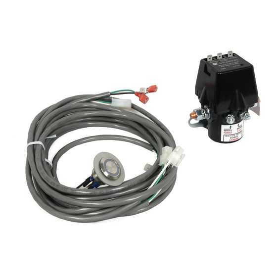
The control cable used in the 10‐01118‐000 kit is a multi‐conductor wire which includes the switch input
signal, the alarm output signal and the ground signal. This cable must go back to the Battery Guard®
1000. It is recommended to leave a service loop or at least 1 ft of extra wire in the run for servicing
purposes. This cable does not need to be run inside of conduit and need any other sort of cabling
protection.
Note: The Battery Guard® 1000 kit includes a 10 ft harness as well as a 10 ft extension harness. Be sure
to use the correct configuration when routing the wires.
Installing the Battery Guard® 1000:
WARNING: Before proceeding, disconnect all sources of power. Unplug the shore power cable and turn
off the generator. Disconnect the battery(s) negative (‐) terminal.
The Battery Guard® 1000 controls a relay that acts as electro‐mechanical switch that disconnects the
battery. It should be located near the battery for wiring simplicity. When installed, the relay will be
inserted "in‐line" with the cable coming from the positive (+) terminal of the battery. Keep this in mind
when choosing the installation location.
WARNING: Do not place between battery and vehicle operation safety critical devices. The Battery
Guard® 1000 will automatically disconnect all loads attached to it when the batteries voltage gets too
low. Please ensure that a separate branch is created for all safety critical device.
While holding the relay in place near the chassis battery, mark the location of the two holes for the relay
mounting bolts. Set the relay aside, and drill two mounting holes. Before bolting the relay in place, route
the Control Cable near the mounting place. When installing in an engine compartment, be sure to
provide enough space for airflow to allow for cooling.
Connecting the Cables:
You must use two wrenches to tighten the nuts on the stud, one to turn the outside nut and
WARNING:
one to hold the nut on the inside from turning. The copper stud must not turn, or relay operation may be
affected.
Locate the positive battery cable for the chassis battery. Carefully cut the cable near the relay. Strip the
cable insulation back about 1/2" on each end and crimp on the battery cable terminals. Remove keps
nuts from both copper studs being careful to leave the existing RED and YELLOW wires in place. Connect
the terminals to the copper studs on the relay. It's important that the battery feed cable goes to the
stud that the existing RED wire is on and the load feed goes to the stud that the existing YELLOW wire is
on. If either wire is not present during installation, then do not continue the installation as the Battery
Guard® will not operate correctly.
Please refer to the wiring diagram on the following page for additional information regarding how to connect to
the Battery Guard® 1000.
53‐01118‐200 Rev B 06/09/2020
Page 2
Advertisement

Summary of Contents for Intellitec Battery Guard 1000 kit
- Page 1 53‐01118‐200 Rev B 06/09/2020 INSTALLATION GUIDE Routing the Control Cable: The control cable used in the 10‐01118‐000 kit is a multi‐conductor wire which includes the switch input signal, the alarm output signal and the ground signal. This cable must go back to the Battery Guard® 1000. It is recommended to leave a service loop or at least 1 ft of extra wire in the run for servicing purposes. This cable does not need to be run inside of conduit and need any other sort of cabling protection. Note: The Battery Guard® 1000 kit includes a 10 ft harness as well as a 10 ft extension harness. Be sure to use the correct configuration when routing the wires. Installing the Battery Guard® 1000: WARNING: Before proceeding, disconnect all sources of power. Unplug the shore power cable and turn off the generator. Disconnect the battery(s) negative (‐) terminal. The Battery Guard® 1000 controls a relay that acts as electro‐mechanical switch that disconnects the battery. It should be located near the battery for wiring simplicity. When installed, the relay will be inserted "in‐line" with the cable coming from the positive (+) terminal of the battery. Keep this in mind when choosing the installation location. WARNING: Do not place between battery and vehicle operation safety critical devices. The Battery Guard® 1000 will automatically disconnect all loads attached to it when the batteries voltage gets too low. Please ensure that a separate branch is created for all safety critical device. While holding the relay in place near the chassis battery, mark the location of the two holes for the relay mounting bolts. Set the relay aside, and drill two mounting holes. Before bolting the relay in place, route the Control Cable near the mounting place. When installing in an engine compartment, be sure to provide enough space for airflow to allow for cooling. Connecting the Cables: You must use two wrenches to tighten the nuts on the stud, one to turn the outside nut and WARNING: ...
- Page 2 53‐01118‐200 Rev B 06/09/2020 INSTALLATION GUIDE WIRING DIAGRAM Note: Color combinations represented in the wiring diagram are from the 10‐01118‐000 kit harnesses. If using a different harness, please refer to the signal definitions when connecting to the device. When Using 10‐01118‐000 kit harness, an additional ground wire from the battery terminal must be connect to the ground quick connect on module (see dashed lines for installation location). *Quick connect receptacle not included in kit. PANEL CUTOUT (Dimensions in inches) RECOMMENDED PANEL CUTOUT Max Panel thickness should not exceed 0.3 inches Note: If using switch as part of the Intellitec kit number 10‐01118‐000 refer to the dimensions above for mounting the switch in the wall. Page 3 ...
- Page 3 53‐01118‐200 Rev B 06/09/2020 INSTALLATION GUIDE Available Product Literature and Guides: Brochure: 53‐01118‐000 Product Specification: 53‐01118‐001 User’s Guide: 53‐01118‐100 Installation and Applications: 53‐01118‐200 Supporting Documents: 53‐01118‐300 Contact Information: www.intellitec.com Intellitec Products, LLC 1485 Jacobs Road, De Land Florida, USA 32724 (386) 738‐7307 Page 5 ...
Need help?
Do you have a question about the Battery Guard 1000 kit and is the answer not in the manual?
Questions and answers