Table of Contents
Advertisement
Quick Links
Advertisement
Table of Contents

Related Manuals for RusAutomation SmartScan 25

Summary of Contents for RusAutomation SmartScan 25
- Page 1 SmartScan User's Manual for SmartScan 25/50...
- Page 2 SmartScan User’s Manual Important Notice This manual is delivered subject to the following conditions and restrictions: ! This manual contains proprietary information belonging to Solid Applied Technologies Ltd. Such information is supplied solely for the purpose of assisting explicitly and properly authorized users of SmartScan.
- Page 3 Safety Guidelines Safety Guidelines Please review the following points before installing and operating the SmartScan system. ! SmartScan must be installed, connected and operated according to the instructions in this Manual. ! If installed incorrectly or used for applications for which it is not intended, application-related dangers may arise.
-
Page 4: Table Of Contents
Wiring the Relays Cable ................32 Wiring VDC Power Cable................ 33 Wiring VAC Power Cable ................ 33 SmartScan 25 Intrensically Safe Connections........... 34 Chapter 3: Basic Setup............... 41 Using the SmartScan Function Buttons ............43 Modifying Numerical Values ..............44... - Page 5 Setting the Indication Mode ..............51 Setting the Measurement Unit..............53 Setting the Relay Values for SmartScan 50 ..........55 Setting the Relay Values for SmartScan 25 ..........64 Setting the 20 mA/4 mA Levels ..............66 Setting the Flow Measurements ............... 67 Setting the Tank Height................
- Page 6 Manually Inserting Strapping Table Values ..........106 Semi-automatic Inserting of Strapping Table Values ......108 Inserting a Coefficient for Readings ............110 Erasing Strapping Table Values .............. 112 Defining 22mA/3.7mA Signal Error Messages........113 Entering Factor for Gas Compensation in SmartScan 25 ......115...
- Page 7 Table of Contents Chapter 6: SmartScan — Resetting configuration parameter..118 Chapter 7: Troubleshooting SmartScan ........119 Appendix A: SmartScan Ranges ..........122 Appendix B: Gas Factor Table for volume only ......124 Appendix C: Flexible cable connector ........127 Index ..................129...
- Page 8 SmartScan User’s Manual viii Table of Figures Figure 1: Front View of SmartScan ............3 Figure 2: Side View of SmartScan ............3 Figure 3: Wall-mount Plate..............4 Figure 4: Back View of SmartScan with Wall-mount Plate...... 4 Figure 5: Panel Mount ................5 Figure 6: Top View of SmartScan with Panel-mount Installation ....
- Page 9 Table of Figures Figure 22: Palmer Bowls Flume Trapezoidal Throat Cross-selection ..89 Figure 23: H Flume ................90 Figure 24: Neyrpic Venturi Flume ............91 Figure 25: Long-base Weir ..............92 Figure 26: Leopold-Lagco Flume............100...
-
Page 11: Chapter 1: Introducing Smartscan
Introducing SmartScan HAPTER Chapter 1 Introducing SmartScan SmartScan is a non-contact, ultrasonic, continuous-level measurement instrument that is able to provide accurate measurements for both liquids and solids, while automatically compensating for changes in temperature and other environmental conditions. SmartScan is designed for applications such as process tanks, storage vessels, open air piles, open channels, and so on. - Page 12 SmartScan User’s Manual The SmartScan product line comprises two families, SmartScan 25 (25 KHz) and SmartScan 50 (50 KHz), each with its own models (as listed below). A variety of sensors are available for SmartScan 25, suitable for different ranges.
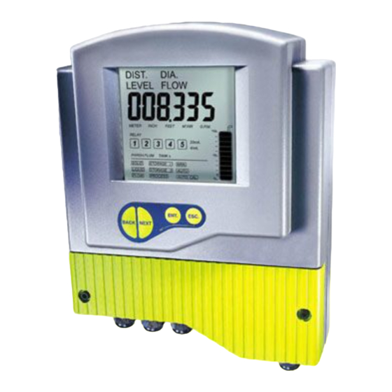
- Page 13 Introducing SmartScan HAPTER The following diagrams show the front and side views of SmartScan, and its dimensions in millimeters: Figure 1: Front View of Figure 2: Side View of SmartScan SmartScan...
-
Page 14: Figure 3: Wall-Mount Plate
SmartScan User’s Manual The following schematic diagrams show the wall-mount and panel-mount options, with the dimensions in millimeters: Figure 4: Back View of Figure 3: Wall-mount Plate SmartScan with Wall-mount Plate... -
Page 15: Figure 5: Panel Mount
Introducing SmartScan HAPTER Figure 5: Panel Mount Figure 6: Top View of SmartScan with Panel-mount Installation... -
Page 16: Sensor Dimensions
SmartScan User’s Manual Sensor Dimensions 25 kHz Standard Range 25 kHz Long Range Sensor Figure 7: SmartScan Sensor Dimensions... - Page 17 Introducing SmartScan HAPTER 50 kHz Sensor Figure 7 (Cont.): SmartScan Sensor Dimensions...
-
Page 18: Smartscan 25 Specifications
SmartScan User’s Manual SmartScan 25 Specifications Measuring Ranges Measuring Ranges Measuring Ranges Measuring Ranges Short Range (Lite) 0.6 m to 10 m (2 ft to 32 ft) Standard Range 0.6 m to 20 m (2 ft to 64 ft) 25L, 25O 0.6 m to 25 m (2 ft to 82 ft) - Page 19 Introducing SmartScan HAPTER Mechanical Specifications Enclosure IP 65/67 (NEMA X4/X6), plastic ABS, wall mount/panel mount Pollution degree 2 (as per IEC61010) Insulation category II (as per IEC61010) Mechanical fitting Gland connection Pg9 Conduit connection 1/2" NPT Conduit connection M20 x 2.5 Temperature range DC model: -40°C to 60°C (-40°F to 140°F) AC model: -20°C to 60°C (-4°F to 140°F)
- Page 20 SmartScan User’s Manual Hazardous Installation version: Max. cable length between unit and Up to 25m (82ft) barriers between sensor and barriers Up to 75m (246ft) Electrical Specifications Electrical Specifications Electrical Specifications Electrical Specifications Display Customized LCD Supply 18 to 30 VDC (0.25 A max), (external fuse: Slow Blow 1A T type***) or 100 —...
- Page 21 Introducing SmartScan HAPTER Certifications Certifications Certifications Certifications CE - EMC,FMC, FM — Safety, FCC Transmitter: FM, (Classified): Non Incendive, Class I,II,III/ Division 2/ Groups ABCDFG/T4 Sensor: Ta = -40°C to +70°C) ATEX: II 1G, EEx ia IIC T4 ( EEx m IIC T4 FM, (Classified): Intrinsically safe Class I,II,III/Division 1/ Groups ABCDEFG/T4 Non Incendive, Class I,II,III/Division 2/ Groups ABCDFG/T4...
-
Page 22: Smartscan 50 Specifications
SmartScan User’s Manual SmartScan 50 Specifications Measuring Ranges asuring Ranges asuring Ranges asuring Ranges SmartScan 50L 0.4 m to 12 m (1.3 ft to 39.4 ft) SmartScan 50S 0.4 m to 8.5 m (1.3 ft to 28 ft) SmartScan 50O 0.4 m to 12 m (1.3 ft to 39.4 ft) Accuracy Accuracy... - Page 23 Introducing SmartScan HAPTER Sensors Sensors Sensors Sensors Wetted parts Polypropylene (PP) (PVDF: optional), glass reinforced epoxy Operating pressure Atmospheric Operating temperature -40° C to 100° C (-40° F to 212° F) Signal power between Min. range: 4Vp-p unit and sensor Max.
- Page 24 SmartScan User’s Manual Certifications Certifications Certifications Certifications CE - EMC,FMC, FM — Safety, FCC Transmitter: FM, (Classified): Non Incendive, Class I,II,III/ Division 2/ Groups ABCDFG/T4 Sensor: EEx m IIC T5 Characteristics Characteristics Characteristics Characteristics Level, distance, flow, volume, kilograms, totalization and diameter.
-
Page 25: Sensor Recommendations
Introducing SmartScan HAPTER Sensor Recommendations 25 kHz Sensor Recommendations 25 kHz Sensor Recommendations 25 kHz Sensor Recommendations 25 kHz Sensor Recommendations Material Description Coated Designed for complex environments with aluminum problematic echoes, such as non-conductive vapors, liquids and solids. (Halar® ® ® ® ECTFE) Good performance in problematic applications. -
Page 26: Sensor Cable Recommendations
Pre cut sensor cables can be modified to fit longer and shorten length than the one that was ordered. For example, if you ordered a sensor for the SmartScan 25 with a 5m/16.4ft cable, you will be able to modify it to a range between 5m/16.4ft to 50m/164ft, or if you ordered a sensor for the SmartScan 50 with 35m/114ft cable you will be able to modify it to fit a range between 5m/16.4ft to... - Page 27 Introducing SmartScan HAPTER 25 kHz Sensor Cable (CE) 25 kHz Sensor Cable (CE) 25 kHz Sensor Cable (CE) 25 kHz Sensor Cable (CE) 25KHz sensor pre cut cable Can be changed to a range of length (m/ft) (m/ft) 5m/16.4ft 5m/16.4ft to 50m/164ft 15m/49.21ft 5m/16.4ft to 50m/164ft 25m/82ft...
- Page 28 SmartScan User’s Manual Flexible cable Flexible cable Flexible cable Flexible cable Flexible sensor cables are supplied with 5m/16.4ft loose-end cable. However, they can be modified to fit longer length than 5m/16.4ft. The modifications in the cable length can be made according to following tables (Shown on Appendix C, page 127): 25 kHz Sensor Cable...
-
Page 29: Chapter 2: Installing Smartscan
Installing SmartScan HAPTER Chapter 2 Installing SmartScan Precautions ! Ensure that the SmartScan components are mounted in an area that meets the stated temperature, pressure and technical specifications. ! Ensure that high-voltage sources or cables are at least 1 m/3.28ft away from the sensor and its cable. -
Page 30: Installing The Smartscan Sensor
SmartScan User’s Manual Installing the SmartScan Sensor The following procedures describe sensor installation using 1" or 2" threading and a correlating locking nut. The installation procedure is the same whether the sensor is mounted directly on the tank or mounted on a pipe. NOTE: If applicable, you can also install the sensor by screwing it directly into the tank or pipe threading. -
Page 31: Threading Options
Installing SmartScan HAPTER To install the sensor using 2" threading (25 kHz standard range sensor): ! Follow the procedure described on the previous page for 1" threading, using a 2" locking nut with the 2" BSP/NPT sensor threading. Threading Options SmartScan sensors are available in BSP or NPT thread types. - Page 32 SmartScan User’s Manual 1" BSP/1" NPT Threading for 50 kHz Sensor 1" BSP/1" NPT Threading for 25 kHz Sensor (Long Range) Figure 8 (Cont.): Sensor Threading Options...
- Page 33 Installing SmartScan HAPTER 2" BSP/2" NPT Threading for 25 kHz Sensor (Standard Range) Figure 8 (Cont.): Sensor Threading Options NOTES: When installing a thread-free flange mounted unit, you will need a 1" or 2" locking nut (depending on the thread type used) to secure the sensor to the tank.
-
Page 34: Sensor Positioning
SmartScan User’s Manual Sensor Positioning When installing the sensor, ensure that it is: ! Mounted above the dead-zone area (blocking distance). NOTE: If the device enters the dead zone, it will not measure correctly. ! Positioned at least 0.5 m (1.64 ft) away from the tank walls. - Page 35 Installing SmartScan HAPTER ! Perpendicular to the surface of the target. NOTE: A tilt in the angle may affect the echo quality ! Install the sensor as far as possible from noisy Filling inlet areas, such as a filling inlet. Figure 9 (Cont.): Sensor Positioning...
-
Page 36: Installing The Sensor Via An Extension Pipe
SmartScan User’s Manual Installing the Sensor via an Extension Pipe If the level of the measured surface falls within the dead-zone area, you should use an extension pipe to mount the sensor. When using an extension pipe, ensure that: ! The sensor is positioned in the center of the pipe. - Page 37 Installing SmartScan HAPTER When installing the sensor with an extension pipe, follow these specifications: 25 kHz and 50 kHz Sensor 25 kHz and 50 kHz Sensor 25 kHz and 50 kHz Sensor 25 kHz and 50 kHz Sensor Pipe Length Internal Pipe Diameter 0.50 m (1.64 ft) ≥3"...
-
Page 38: Wiring The Smartscan Unit
SmartScan User’s Manual Wiring the SmartScan Unit The lower part of the SmartScan unit consists of the electrical unit, which contains the wiring terminals for the sensor cable and the power cable. The electrical unit also contains optional connectors for monitoring of digital and analog outputs, as well as five optional relay connectors. -
Page 39: Wiring The Sensor Cable
Installing SmartScan HAPTER In order to make a wiring connection, remove the ribbed faceplate covering the electrical unit using a 3-mm Allen wrench. Ensure that the cover is replaced securely after all wiring connections are completed. To wire and install the SmartScan: 1 Install the sensor, as described in Installing the SmartScan Sensor, page 20. - Page 40 SmartScan User’s Manual To wire the sensor cable to JP5: NOTE: Ensure that the power is switched off before wiring the sensor cable. 7 Thread the sensor cable through aperture (C1), located on the right side of the SmartScan electrical unit’s base. 8 Connect each colored wire in the cable to the appropriate screw-down termination post at terminal JP5, according to the color coding given in the table below (if...
-
Page 41: Wiring The Monitoring Cables
Installing SmartScan HAPTER Wiring the Monitoring Cables SmartScan data can be monitored on a PC via an RS-485 or RS-232 connection to terminal JP22. You can also connect SmartScan to an analog output meter, set between 4 mA and 20 mA, using terminal JP32. (Setting the 4 mA and 20 mA values is described in Chapter 3, Basic Setup.) To wire the digital interface cable to JP22: 1 Thread the required cable through the wiring apertures... -
Page 42: Wiring The Relays Cable
SmartScan User’s Manual Wiring the Relays Cable SmartScan’s electrical unit provides connectors at terminal JP26 for up to five independently programmable relays. The relays can be used to initiate certain actions, such as controlling pumps, triggering an alarm or sending a warning message, when a defined value is reached. -
Page 43: Wiring Vdc Power Cable
Installing SmartScan HAPTER Wiring the VDC Power Cable The free end of SmartScan’s power cable is connected to the electrical unit using terminal JP2 when working in VDC. To wire the power cable to JP2: 1 Thread the required cable through C2 aperture at the base of the electrical unit. -
Page 44: Smartscan 25 Intrensically Safe Connections
SmartScan User’s Manual SmartScan 25 Unit - Intrinsically Safe Connections Hazardous Area Installation Hazardous Area Installation Hazardous Area Installation Hazardous Area Installation (For Ex version) Installation of the equipment shall be in accordance with the NEC Articles 504 and 505 and ISA RP 12.06.01 Recommended Practice for the Installation of Intrinsically Safe Circuits. - Page 45 Installing SmartScan HAPTER being adversely affected, thus ensuring that the type of protection is not compromised. ! ! ! ! The certificate number has an ’X’ suffix that indicates that the following special condition of certification applies; ! ! ! ! The supplies from the two intrinsically safe barriers must be prevented from combining with each other in the supply cable by using separate cables or a cable with a screen around each circuit.
- Page 46 SmartScan User’s Manual SPECIAL CONDITIONS FOR SAFE USE Equipment intended for use in Potentially Explosive Atmospheres Directive 94/9/EC The following instructions apply to equipment covered by certificate number:Sira 04ATEX5339X Ultrasonic Sensor 25Khz & 50Khz. ! ! ! ! The ’X’ suffix to the certificate number relates to the following special conditions for safe use: ! ! ! ! The sensors shall not be located in direct sunlight or light from luminaires.
-
Page 47: Figure 11A: Intrinsically Safe Connections
HAPTER Wiring the Sensor Cable to the Barriers (for IS only) SmartScan 25 sensor cable should be connected to Zener barriers (refer to the barriers’ specifications detailed on page 37), to prevent high voltage bursts and to protect the unit from damage. - Page 48 SmartScan User’s Manual Wiring the Transducer to the Barriers To wire the sensor cable to the transducer barrier: 1 Screw-down the sensor’s green (GR) wire to the barrier’s termination post (3). 2 Screw-down the sensor’s brown (BR) wire to the barrier’s termination post (4).
- Page 49 Installing SmartScan HAPTER To wire the temperature barrier to terminal JP5 in the SmartScan unit: Thread the sensor cable through aperture (C1), located on the right side of the SmartScan electrical unit’s base. 1 Screw-down the sensor’s white (WH) wire (4) first end to the barrier’s termination post (1) and the other end to terminal JP5 termination post (4).
- Page 50 SmartScan User’s Manual Barriers Specifications Transducer Circuit Barriers Interconnection Producer Zener Barrier Intrinsic Safety Barrier SmartScan Part Number Approval Terminal Terminal 7778ac CSA, ATEX, FM, UL STAHL 9002/77- CSA, ATEX, 280-094-00 FM, UL Temperature Sensor Circuit Barriers Interconnection Producer Zener Intrinsic Safety Barrier SmartScan...
-
Page 51: Chapter 3: Basic Setup
Basic Setup HAPTER Chapter 3 Basic Setup This chapter describes how to set up and calibrate SmartScan for accurate measurement monitoring using the basic menu options. SmartScan is supplied with preprogrammed default settings, making it ready for immediate operation. Measurement readings are displayed on the default screen as soon as the unit is powered on, as described in Default Screen, page 48. -
Page 52: Figure 12: Smartscan Main Menu Screen
SmartScan User’s Manual Indication modes Numerical area 20 mA/4 mA Measurement levels units Relays Tank graphic Flow measurements Application types Operation Tank height modes Sensor offset Scan distance mode indicator Clear scan distance Figure 12: SmartScan Main Menu Screen NOTE: The options displayed in the main menu depend on the SmartScan model so you may not necessarily view all the options shown in the above example. -
Page 53: Using The Smartscan Function Buttons
Basic Setup HAPTER Using the SmartScan Function Buttons The function buttons are used to perform various operations, summarized in the following table. Button Uses Include: ! Accessing the menus (when pressed simultaneously with ! Accessing a function within a menu, enabling you to make modifications. -
Page 54: Modifying Numerical Values
SmartScan User’s Manual Modifying Numerical Values Within some functions, the value displayed in the numerical area can be modified. The digit currently available for modification is displayed flashing (flashing digits are shown in gray in the illustrations, for example, ). The value is modified by using the buttons to move between the digits, and by using the... -
Page 55: Menu And Version Selection
Basic Setup HAPTER Menu and Version Selection SmartScan has two menus, the main menu and the additional menu. To access each of these, you must select the appropriate digit in the numerical area of the display screen. After selecting the required digit (by pressing the ENT button), the corresponding number icon flashes in the LCD, indicating that SmartScan is entering the selected version mode or menu. -
Page 56: Accessing The Main Menu
SmartScan User’s Manual Accessing the Main Menu This chapter describes access and setup for SmartScan 25 and 50. The SmartScan main menu screen (shown on page 42) is accessed from the default screen, using the function buttons located under the LCD. -
Page 57: Using The Main Menu
Basic Setup HAPTER Press/Action Display Explanation µ Required option to flashes for approximately access the main menu. 5 seconds, then is displayed. µ flashes for A representation of the main menu screen is approximately 5 seconds, then shown on page 42. the main menu screen is displayed. -
Page 58: Default Screen
SmartScan User’s Manual The level of the tank graphic displayed in the main menu screen moves up from 0 to 100% when you save an option or when SmartScan is processing. After saving an option, the main menu is displayed with the next option flashing. Default Screen As soon as SmartScan is fully installed and powered on, the LCD displays the default screen. - Page 59 Basic Setup HAPTER The tank graphic in the default screen gives an approximate visual indication of the current level of the tank contents, while the numerical area gives the exact reading. If the level enters the dead zone, the numerical area displays if the tank is empty, the numerical area displays the tank height.
-
Page 60: Setting Main Menu Options
SmartScan User’s Manual Setting Main Menu Options The following functions are available in the SmartScan main menu. Refer to page 51. Refer to page 53. Refer to page 55. Refer to page 66. Refer to page 67. Refer to page 68. Refer to page 70. -
Page 61: Setting The Indication Mode
Basic Setup HAPTER Setting the Indication Mode The first function in the main menu is the indication mode. The following indication options are available, depending on the SmartScan model: ! DIST: (Default setting) The displayed reading represents the distance from the sensor to the surface of the tank contents. - Page 62 SmartScan User’s Manual Indication Indication Toggle Option Distance/Level Distance/Level Flow/Level/Distance/ Totalization Flow (High)/Totalization (Low) Totalization Totalization/Distance/Flow Volume Volume/Level/Distance To set the indication mode: Press/Action Display Explanation µ Use to move between the available options. µ For example, Displays the selected Press option for a few save the selected...
-
Page 63: Setting The Measurement Unit
Basic Setup HAPTER Setting the Measurement Unit SmartScan enables you to set the measurement unit used for the displayed readings, according to your requirements and the measurement function. The following measurement options are available: ! METER (default unit), INCH or FEET: Select one of these options for distance measurements. - Page 64 SmartScan User’s Manual NOTE: If you select METER, any relevant flow measurements will be in metric units, meaning M /HR. The opposite also applies, so that if you select /HR, any relevant distance or level measurements will be in meters. If you select INCH or FEET, any relevant flow measurements will be in G.P.M.
-
Page 65: Setting The Relay Values For Smartscan 50
Basic Setup HAPTER Setting the SmartScan 50 Relay Values You can set the relays to five different configuration modes: Level, Distance and Flow (where applicable), Volume and Totalization (the last two modes should be configured only after Volume/Totalization options were enabled in the Chapter 5, Additional Features). - Page 66 SmartScan User’s Manual In addition, relay four (4) can be configured to report error messages and relay five (5) for flow totalization pulse setup (see detailed configuration instructions on pages 62, 63). The relay values function as follows: ! Open value: (Default = 0) The relay opens if the level measured in the tank is higher than the entered open value.
- Page 67 Basic Setup HAPTER To set the relay values for level or distance: Press/Action Display Explanation µ With the RELAY icon to enter relay flashing. setup. µ Choose the desired relay to assign an configuration mode: Level, indication mode Distance, Flow, for the relays.
- Page 68 SmartScan User’s Manual Press/Action Display Explanation µ Use to enter the relay to enter values value. for the relay. µ Enters close values mode of Press at the the relay setup. Enter and end of entering a save the close values in the value for relay 1, to same way as described enter close value...
- Page 69 Basic Setup HAPTER Relays values can be configured in two separate screens when set to flow, volume or totalization (after setting the SmartScan was set to of these indications). To set the relay values for flow: Press/Action Display Explanation µ With the RELAY icon to enter relay flashing.
- Page 70 SmartScan User’s Manual Press/Action Display Explanation µ For example, Use this screen to enter Low numbers of up to five digits of flow values. µ Enter relay values for Close mode, as described above for Open mode. As shown in the above example, relay values were configured in the following way: 000001 was entered in the high numbers H=1 and 20,000 was entered in the low numbers L=20,000 which mean a total value of 120,000 gallons.
- Page 71 Basic Setup HAPTER Setting relay 4 to report errors This mode enables you to use the relay as a trigger to set on an alarm or siren in case the unit produces inaccurate measurement results due to an electrical failure or acoustic problem. You can configure relay 4 to report errors or to remain in normal set-up mode.
- Page 72 SmartScan User’s Manual Setting relay 5 for flow totalization pulse indication You can choose to set relay number five (5) for flow totalization pulse indication or to remain in normal set-up mode. This option enables you to reserve the accumulated value gathered by the unit, by using an external counter.
- Page 73 Basic Setup HAPTER To set relay 5 for pulse indication: Press/Action Display Explanation µ Move to relay 5 using NEXT or BACK buttons and ENT. to enter the desired operation mode. µ Choose tot En to enable to select pulse indication option or enable or tot-ds to disable this disable mode.
-
Page 74: Setting The Relay Values For Smartscan 25
SmartScan User’s Manual Setting the SmartScan 25 Relay Values You can set up to five relay switches for SmartScan 25. Each relay enables you to define open and close values for the switch, for functions such as triggering an alarm. - Page 75 Basic Setup HAPTER To set the relay values for level or distance: Press/Action Display Explanation µ With the RELAY icon to enter relay flashing. setup. µ Enters the open values to enter mode of the relay setup. open mode. The relay number flashes throughout the process of defining its values.
-
Page 76: Setting The 20 Ma/4 Ma Levels
In both distance and level measurement modes, the dead-zone area affects the maximum values that can be used for 20 mA/4 mA levels. For SmartScan 25 models, the maximum 20 mA/4 mA value is tank height minus 0.6 m/1.9 ft. For SmartScan 50 models, the maximum 20 mA/4 mA value is tank height minus 0.4 m/1.3 ft. -
Page 77: Setting The Flow Measurements
Basic Setup HAPTER Press/Action Display Explanation µ Use to enter the new value. (Function button use is described on page 43.) The values of 4-20mA are application dependable. For example, when measuring distance the value will be in distance (same for level). NOTE: VOLUME values in 4-20mA are represented by six digits (the same applies for FLOW values). -
Page 78: Setting The Tank Height
SmartScan User’s Manual Setting the Tank Height You can enter the height of your tank using the TANK h function. The default value is the maximum value in the relevant measurement range for your SmartScan model (refer to the range table in Appendix A, SmartScan Ranges). If you enter a value that exceeds this maximum value, an error message is displayed. - Page 79 Basic Setup HAPTER To set the tank height value: Press/Action Display Explanation µ Select the desired measurement method from the indication modes: DIST, LEVEL, DIA. Using NEXT or BACK buttons. µ Displays the selected option to save for a few seconds and a the selected flashing tank graphic.
-
Page 80: Setting The Application Type
SmartScan User’s Manual Setting the Application Type The SmartScan main menu displays (by default) SOLID, for models intended for solid applications, or LIQUID for models intended for liquid. When SmartScan unit is configured as either LIQUID or FLOW (open channel) model, selecting FLOW option from the indication mode automatically selects the FLOW option in the application types menu. -
Page 81: Setting The Operation Modes
Basic Setup HAPTER Setting the Operation Modes The operation modes function enables you to set SmartScan to compensate for environmental conditions that affect the measurement readings. For solid and liquid applications, each mode determines the reaction time required for SmartScan to recalibrate when there is a change in the environmental conditions. - Page 82 SmartScan User’s Manual Liquid Modes Three modes are available for SmartScan liquid-application models. Each mode is recommended for use as follows: : Recommended in the following conditions: O Wavy surfaces O Slow filling/emptying rate O Applications where the sensor is installed near the tank wall : (Twice as fast as STORAGE I.) Recommended in the following conditions:...
- Page 83 Basic Setup HAPTER Solid Modes Three modes are available for SmartScan solid-application models. The main difference between the modes is in the search process required to select the correct echo. Each mode is recommended for use in the following conditions: : Very dusty environments (such as cement) : Grain applications...
-
Page 84: Setting The Scan Distance Values
SmartScan User’s Manual Setting the Scan Distance Values Figure 145: Scan Distance Process Up to eight interfering signals (false echoes) can be located by SmartScan and stored in its memory. The false echoes, which may be caused by obstructions such as a tank agitator or a side wall, can generate false readings and so interfere with the true scanning of the tank contents. - Page 85 Basic Setup HAPTER Each scan distance reading is stored as an interfering signal until a reading is achieved that indicates the true echo. If eight interfering signals are already stored and a ninth reading is received, the first value stored is deleted and the new one saved.
- Page 86 SmartScan User’s Manual Press/Action Display Explanation this process to save up to eight interference readings. µ For example, Actual target height reading indicates that there are no more interfering signals. µ Saves the true echo value and completes the scan distance operation.
-
Page 87: Clearing The Scan Distance Values
Basic Setup HAPTER Clearing the Scan Distance Values The AUTO function enables you to clear all saved scan distance values. (Refer to Setting the Scan Distance Values, page 74, for a description of how to set the scan distance values.) To clear scan distance values: Press/Action Display... - Page 88 SmartScan User’s Manual To view processor information: Press/Action Display Explanation µ In the main menu display, press simultaneously. µ Use to enter the value 000.003. µ The version number of the Press on the example, screen processor is far-right digit. displayed.
-
Page 89: Chapter 4: Smartscan Open Channels
SmartScan Open Channels HAPTER Chapter 4 SmartScan Open Channels This chapter describes how to set flow measurement parameters for open channels using SmartScan 50O models, and explains the flume/weir codes methodology used when setting up flow measurements. NOTE: Refer to Chapter 3, Basic Setup, for an explanation of accessing and using the SmartScan main menu and function buttons. - Page 90 SmartScan User’s Manual When setting flow-measurement parameters, the flume/weir type value (X) is entered first, followed by the letter (U) or (E) as an indication for American or European open channel flow standard and followed by the code value (YY) that represents the appropriate flume/weir dimensions, in the following format: .
-
Page 91: Open Channels Flow Measurements
SmartScan Open Channels HAPTER Press/Action Display Explanation µ Use to select a new flume/weir length code (YY), which corresponds to the type (X) previously selected. (The two digits are modified as one unit.) µ The selected values are saved. Open Channels Flow Measurements The flume/weir type code methodology used when setting up open channels is based on three digits: X E/U YY Where:... -
Page 92: Flume/Weir Types
SmartScan User’s Manual Flume/Weir Types This is the first value (X) entered for the PARSH.FLUME function. The following flume/weir types are available both in European and American standard: Type European Standard (E) American Standard (U) Pages 83-91 Pages 93-100 Rectangular Suppressed Rectangular Suppressed Sharp- Sharp-Crested Weir, Page 83 Crested Weir, Page 93... -
Page 93: European Standard
SmartScan Open Channels HAPTER Flumes/Weirs Flumes/Weirs - - - - European Standard European Standard Flumes/Weirs Flumes/Weirs European Standard European Standard Rectangular Suppressed Sharp Rectangular Suppressed Sharp- - - - Crested Rectangular Suppressed Sharp Rectangular Suppressed Sharp Crested Crested Crested Weir (Type 1) Weir (Type 1) Weir (Type 1) Weir (Type 1) -
Page 94: Rectangular Contracted Sharp-Crested Weir (Type 2)
SmartScan User’s Manual Rectangular Contracted Sharp- - - - Crested Rectangular Contracted Sharp Crested Rectangular Contracted Sharp Rectangular Contracted Sharp Crested Crested Weir (Type 2) Weir (Type 2) Weir (Type 2) Weir (Type 2) Code (YY) Crest Length (cm) Figure 17: Rectangular Contracted Sharp-Crested Weir... -
Page 95: Trapezoidal (Cipolletti) Sharp-Crested Weir (Type 3)
SmartScan Open Channels HAPTER Trapezoidal (Cipolletti) Sharp Trapezoi dal (Cipolletti) Sharp- - - - Crested Crested Trapezoi Trapezoi dal (Cipolletti) Sharp dal (Cipolletti) Sharp Crested Crested Weir (Type 3) Weir (Type 3) Weir (Type 3) Weir (Type 3) Code (YY) Crest Length (cm) Figure 18: Trapezoidal (Cipolletti) Sharp-Crested Weir... -
Page 96: V-Notch (Triangular) Sharp-Crested Weir (Type 4)
SmartScan User’s Manual V V V V - - - - Notch (Triangular) Sharp Notch (Triangular) Sharp- - - - Crested Crested Notch (Triangular) Sharp Notch (Triangular) Sharp Crested Crested Weir (Type 4) Weir (Type 4) Weir (Type 4) Weir (Type 4) Code (YY) V-Notch Angle ( 53.8... -
Page 97: Khafagi-Venturi Flume (Type 5)
SmartScan Open Channels HAPTER Khafagi- - - - Venturi Flume Khafagi Venturi Flume (Type 5) (Type 5) Khafagi Khafagi Venturi Flume Venturi Flume (Type 5) (Type 5) Code (YY) Flume Type b0 (cm) QV 302 QV 303 QV 304 QV 305 QV 306 QV 308 QV 310... - Page 98 SmartScan User’s Manual Parshall Flume (Type 6) Parshall Flume (Type 6) Parshall Flume (Type 6) Parshall Flume (Type 6) Code Throat Code Throat (YY) Width (in) (YY) Width (in) Figure 21: Parshall Flume...
-
Page 99: Figure 22: Palmer Bowls Flume Trapezoidal Throat Cross-Selection
SmartScan Open Channels HAPTER Palmer Bowlus Flume Trapezoidal Palmer Bowlus Flume Trapezoidal Palmer Bowlus Flume Trapezoidal Palmer Bowlus Flume Trapezoidal Throat Cross- - - - Selection (Type 7) Throat Cross Selection (Type 7) Throat Cross Throat Cross Selection (Type 7) Selection (Type 7) Code (YY) Conduit Diameter (in) D... - Page 100 SmartScan User’s Manual H Flume (Type 8) H Flume (Type 8) H Flume (Type 8) H Flume (Type 8) Code (YY) Flume Size Measurement (ft) Point (cm) 0.75 Figure 23: H Flume...
-
Page 101: Figure 24: Neyrpic Venturi Flume
SmartScan Open Channels HAPTER Neyrpic Venturi Neyrpic Venturi Flume/Long Flume/Long- - - - Base Weir Base Weir Neyrpic Venturi Neyrpic Venturi Flume/Long Flume/Long Base Weir Base Weir (Type 9) (Type 9) (Type 9) (Type 9) Neyrpic Venturi Flume Neyrpic Venturi Flume Neyrpic Venturi Flume Neyrpic Venturi Flume Code (YY) -
Page 102: Figure 25: Long-Base Weir
SmartScan User’s Manual Long- - - - Base Weir Long Base Weir Long Long Base Weir Base Weir Code Long-Base (YY) Weir Type 1245A 1245B 1245C 1245D Figure 25: Long-Base Weir... - Page 103 SmartScan Open Channels HAPTER Flumes/Weirs Flumes/Weirs – – – – American Standard American Standard Flumes/Weirs Flumes/Weirs American Standard American Standard Rectangular Suppressed Sharp Rectangular Suppressed Sharp Rectangular Suppressed Sharp Rectangular Suppressed Sharp- - - - Crested Crested Crested Crested Weir (Type 1) Weir (Type 1) Weir (Type 1) Weir (Type 1)
- Page 104 SmartScan User’s Manual Rectangular Contracted Sharp-Crested Weir (Type 2) Code (YY) Crest Length (in) 12.00 18.00 24.00 30.00 36.00 48.00 60.00 72.00 96.00 Figure 17: Rectangular Contracted Sharp-Crested Weir...
- Page 105 SmartScan Open Channels HAPTER Trapezoidal (Cipolletti) Sharp- - - - Crested Trapezoidal (Cipolletti) Sharp Crested Trapezoidal (Cipolletti) Sharp Trapezoidal (Cipolletti) Sharp Crested Crested Weir (Type 3) Weir (Type 3) Weir (Type 3) Weir (Type 3) Code (YY) Crest Length (in) 12.00 18.00 24.00...
- Page 106 SmartScan User’s Manual V V V V - - - - Notch (Triangular) Sharp Notch (Triangular) Sharp Notch (Triangular) Sharp- - - - Crested Weir Notch (Triangular) Sharp Crested Weir Crested Weir Crested Weir (Type 4) (Type 4) (Type 4) (Type 4) Code (YY) V-Notch Angle (...
- Page 107 SmartScan Open Channels HAPTER Parshall Flume (Type 5) Parshall Flume (Type Parshall Flume (Type Parshall Flume (Type Code Throat Code Throat (YY) Width (in) (YY) Width (in) Figure 20: Parshall Flume...
- Page 108 SmartScan User’s Manual Palmer Bowlus Flume Trapezoidal Throat Cross-Selection (Type 6) Code (YY) Conduit Code (YY) Conduit Diameter (in) D Diameter (in) D Figure 21: Palmer Bowls Flume Trapezoidal Throat Cross-Selection...
- Page 109 SmartScan Open Channels HAPTER H Flume (Type 7) Code Flume Size Measurement (YY) (in) Point (in) 1.96 2.75 3.54 5.51 7.08 9.05 11.02 16.14 Figure 22: H Flume...
-
Page 110: Figure 26: Leopold-Lagco Flume
SmartScan User’s Manual Leopold Leopold- - - - Lagco Flume (Type 8) Lagco Flume (Type 8) Leopold Leopold Lagco Flume (Type 8) Lagco Flume (Type 8) Code (YY) Crest Length Code (YY) Crest Length (in) (in) Figure 26: Leopold Lagco Flume... - Page 111 Additional Features HAPTER Chapter 5 Additional Features This chapter describes the functions available in SmartScan’s additional menu. The additional menu functions enable you to calibrate SmartScan to perform the following tasks: ! Present scanning results in volume format. ! Present scanning results as a total accumulative value for flow.
- Page 112 For SmartScan 50 models: Press once on the ESC. button to return to the main menu and twice to return to the default screen. For SmartScan 25 models: Press once on the ESC. button to return to the default screen.
- Page 113 Additional Features HAPTER Setting Additional Menu Options You can access and modify the additional menu functions in any order. The options available within the functions, and their practical application for SmartScan functioning, are dependent on the SmartScan model being used. The following functions are available in the SmartScan additional menu.
- Page 114 SmartScan User’s Manual Selecting an Indication Using function Pr 0, you can modify the SmartScan default display to show indications for volume, total flow or diameter sum. Select the required indication mode, as follows: ! Ind 1: Volume mode. The default screen indicates the volume reading, by means of a value displayed in the numerical area and the level of the tank graphic.
- Page 115 Additional Features HAPTER ! 0: Resets the totalization value ! 1: Activates the totalization mode ! 2: Deactivates the totalization mode To select an indication: Press/Action Display Explanation µ Required menu selection. µ For example, Displays an indication option. µ For example, Use to select the required indication option.
- Page 116 SmartScan User’s Manual Manually Inserting Strapping Table Values The Pr 1 function enables you to manually create a strapping table of distance points for either volume calculations or custom flume measurements, for the SmartScan 25O and 50O models. The strapping table is used for manual insertion of distance/volume values when IND 1 was selected as the value for Pr 0, as described in Selecting an Indication, page 104.
- Page 117 Additional Features HAPTER To insert strapping table values manually: Press/Action Display Explanation µ Required menu selection. µ Setup for the first point. µ Displays 0 or the previously saved value. µ Use to enter the distance value (in the measurement unit defined for SmartScan operation).
- Page 118 SmartScan User’s Manual Press/Action Display Explanation digit. point. Using the buttons, you can enter one digit after the decimal point. µ Repeat the above procedure Press after for each point to be inserted entering one in the table. digit after the decimal point.
- Page 119 Additional Features HAPTER NOTES: You can exit Pr 2 at any stage by pressing the ESC button. However, it is recommended that you first enter at least eight points for the function. The same strapping table is used for functions Pr 1 and Pr 2. Any change made from either of the functions will be applied to the one mutual table.
- Page 120 SmartScan User’s Manual Press/Action Display Explanation in this table described for the manual entry. procedure on page 103. µ Repeat the above procedure for each point to be inserted in the table. NOTES: 4-20mA parameters in volume mode are identical to the volume values entered in the strapping table.
- Page 121 Additional Features HAPTER K = The factor difference between the previous measurement unit and the current unit X = Result according to the previous unit (such as meters, feet or inches) ! Converting volume values to percentages and vise versa: Variables represent volume values displayed in percentages: Y = Measured values displayed in percentage...
- Page 122 SmartScan User’s Manual Press/Action Display Explanation Erasing Strapping Table Values The Pr 4 function erases all values entered in the strapping table using functions Pr 1 or Pr 2, as described on pages 106 and 108. To erase strapping table values: Press/Action Display Explanation...
- Page 123 Additional Features HAPTER Defining 22mA/3.7mA Signal Error Messages The Pr 6 function allows you to define whether the following signal error indications Near Zone and Lost Echo will be active when the current output reaches 22mA or 3.7mA. The SmartScan default setting enables 22mA analog current and error messages to appear on its LCD display.
- Page 124 SmartScan User’s Manual To select 22mA/3.7mA signal error messages: Press/Action Display Explanation µ Required menu selection. µ 22mA signal error messages will be activated. µ Use to toggle between the options. NOTE: The factory default for Error Signal mode is disable.
- Page 125 Additional Features HAPTER Entering Factor for Gas Compensation in SmartScan 25 for volume only. Function Pr.07 enables you to compensate for sound velocity changes in different types of gas. You can enter the appropriate factor for each type of gas listed on the ‘Gas Factor Table’...
- Page 126 SmartScan User’s Manual To enter a gas compensation factor: Press/Action Display Explanation µ Required menu selection. µ Displays the default factor. µ A gas factor for Ammonia is example, entered. µ The displayed measurement example, value compensated including the gas factor will flash for 10 seconds.
- Page 127 SmartScan — Resetting configuration parameter HAPTER Chapter 6 SmartScan – Resetting configuration parameter Step operation note Power-on measurement ENT + ESC ENTx2 ENTx2 Main Manu Back+Next 000.000 ENTx5 000.000 Next...
- Page 128 SmartScan User’s Manual 000.001 to change 000.000 ENTx1 000.000 Next Change to Solid 000.001 Enter for Solid - wait 000.001 000.001 Back Change to Liquid - wait 000.000 Enter for Liquid 000.000 ESCx2 Exit to Measurement measurement 000.000 Reconfiguration...
- Page 129 Troubleshooting SmartScan HAPTER Chapter 7 Troubleshooting SmartScan This chapter describes the error messages displayed when an illegal value is entered for a SmartScan function, or when an option is selected that is not applicable for the specific SmartScan model you are using. If an illegal value is entered, the appropriate error message is displayed flashing while the level of the tank graphic on the bottom-right of the screen moves up from 0 to 100%.
- Page 130 SmartScan User’s Manual The Close value entered for a relay is greater than the Open value entered for the relay. The value entered for 4 mA is equal to the value entered for 20 mA. The selected function/option is not applicable for the SmartScan model in use.
- Page 131 Troubleshooting SmartScan HAPTER 22mA/3.7mA Signal Error Messages 22mA/3.7mA Signal Error Messages 22mA/3.7mA Signal Error Messages 22mA/3.7mA Signal Error Messages The following list of messages will appear on the display and coincides with a 22mA or 3.7mA (depends on your set-up) analog current error output signal (the default is set to 22mA): Error Description...
- Page 132 SmartScan User’s Manual Appendix A SmartScan Ranges This appendix provides the maximum and minimum permitted values for the main menu functions in the SmartScan 50 and SmartScan 25 units. Permitted Values for SmartScan Function Permitted Values Solid, Liquid and Flow...
- Page 133 SmartScan Ranges PPENDIX Permitted Values for SmartScan Function Permitted Values Solid, Liquid and Flow for SmartScan 25 Applications 4 mA level From 0 up to From 0 up to maximum tank maximum height tank height 20 mA level From 0 up to...
- Page 134 SmartScan User’s Manual Appendix B Gas Factor Table This following table contains 33 different types of gas and their factor for compensating sound velocity. Entering the desired factor (refer to Chapter 5, Additional Features for more details) will immediately change the measurement results to fit your application requirements for measuring volume only.
- Page 135 Gas Factor Table PPENDIX Symbol CAS No. Factor Bromochlorodiflu oromrthane Cbrclf 353-59-3 0.38 Butanone CH3COCH2CH3 78-93-3 0.56 Carbon Dioxide 124-38-9 0.78 Carbon Monoxide 630-08-0 1.02 Carbon CCI4 56-23-5 0.39 Tetrachloride Chlorine 0.63 Dimethyl Ether C2H6O 115-10-6 0.71 Ethane C2H6 74-84-0 0.90 Ethanol C2H6O...
- Page 136 SmartScan User’s Manual Symbol CAS No. Factor Isopropyl 67-63-0 Alcohol C3H8O 0.62 Methane 74-82-8 1.30 Methanol CH4O 67-56-1 0.88 Methyl 60-34-4 Hydrazine CH6N2 0.71 Neon 1.30 Nitrogen 1.02 Nitromethane CH3NO2 75-52-5 0.63 Oxygen 0.95 Propane C3H8 74-98-6 0.73 Propanol C3H8O 71-23-8 0.61 Sodium...
- Page 137 Appendix C PPENDIX Appendix C Flexible Cable connector Preparing sensor’s cable Connection to Soldering to Smart Main Box Sensor Board Cable length = according to order solder Blue, 24AWG wire to the cable shield. Apply shrink on soldering area. The flexible cable option allows users to increase the cable length of the sensor.
- Page 138 SmartScan User’s Manual When the order includes longer cable adapter than the supplied cable a cable connector should be added The female part will be supplied separately, per the following:...
- Page 139 Index Index 20 mA level, 66 Certifications, 11, 14 Characteristics, 11,14 Coefficient value, 110 4 mA level, 66 Custom flume 4-20 mA enabling, 106 wiring, 31 measurements, 81 Strapping table Default screen, 48 erasing values, 112 Dimensions manual insertion, 106 sensors, 6 semi-automatic insertion, 108 Distance mode, 51...
- Page 140 SmartScan User’s Manual H, 90, 99 Khafagi-Venturi, 87 Level mode, 51 Neyrpic Venturi, 91 Liquid Palmer Bowls Trapezoidal Throat mode, 72 Cross-selection, 89, 98 operation modes, 71 Parshall, 88, 97 Long-base Weir, 91 Function buttons, 43 Functions accessing, 43 Main menu list, 43 accessing, 46 permitted values, 121...
- Page 141 Index flume/weir types, 82 measurement settings, 79 Scan distance Operation modes clearing values, 75 liquid, 72 setting values, 74 setting, 71 Sensor deviation, 74 solid, 73 Sensors cable wiring, 29 dimensions, 6 Palmer Bowlus Flume Trapezoidal installing, 20 Throat Cross-selection, 89, 98 installing via extension pipe, 26 Parsh.flum, 106 positioning, 26...
- Page 142 SmartScan User’s Manual mechanical, 9, 12 sensors, 9, 13 Weirs SmartScan 25 models, 8 Long-base, 92 SmartScan 50 models, 12 Rectangular Contracted Storage options, 72 Sharp-crested, 84, 94 Rectangular Supressed Sharp-crested, 83, 93 Tank height Trapezoidal (Cipolletti) setting, 56 Sharp-crested, 85, 95...
Need help?
Do you have a question about the SmartScan 25 and is the answer not in the manual?
Questions and answers