
Related Manuals for SCI WLS555

Summary of Contents for SCI WLS555
- Page 1 WLS555 Installation and Operation Manual SCI-WLS555 Onboard Weighing System Installation Guide V4.1...
- Page 2 Service, Operation, or Maintenance Manuals. It is your sole responsibility to install, operate, and maintain the SCI system in a manner that will not cause damage to persons, property, or anything else. Always use safe practices and adhere to any laws that may be in place.
-
Page 3: Table Of Contents
WLS555 INSTALLATION AND OPERATION MANUAL Table of Contents Important Safety Information ....................A Table of Contents ........................1 Introduction ........................2 1.1. Compatibility Statements ..................2 1.2. Approved Devices ...................... 2 1.3. How the System Works ..................... 2 1.4. Components ....................... 4 1.5. -
Page 4: Introduction
WLS555 INSTALLATION AND OPERATION MANUAL Introduction Thank you for purchasing the WLS555 Onboard Weighing System. This product has been designed to be simple to install and operate. The system operates with communication from the processor to a mounted tablet or handheld device. Please ensure you have read and understand the compatibility statements to ensure the best experience. - Page 5 If the system has a printer configured, it will also print the load ticket once FINISH is pressed. On SCI supplied Brother printer, pressing the feed button on the printer will reprint the last ticket.
-
Page 6: Components
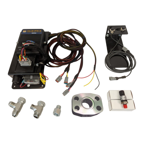
WLS555 INSTALLATION AND OPERATION MANUAL 1.4. Components Standard Components Figure 1 1. Controller Assembly – This has the processing module, I/O module, and fuse block. All other wired components get connected to this assembly. 2. Switch Assembly – This part gets mounted (welded or bolted) to the frame where the loader arm pivots. - Page 7 WLS555 INSTALLATION AND OPERATION MANUAL Optional Components Figure 2 1. Display (Optional) – Samsung Tab Active or Tab A7 Lite Tablet or your device. 2. Display Mount (Optional) – This comes in many variations. Consult your order to ensure compatibility with your handheld device.
-
Page 8: Typical Mounting Locations
WLS555 INSTALLATION AND OPERATION MANUAL 1.5. Typical Mounting Locations Mounting on Wheel Loader Figure 3 Mounting on Skid Steer Figure 4 1. Controller Assembly – Mounted outside cab away from falling debris 2. Switch Assembly – Left hand side at / near loader arm pivot point 3. -
Page 9: Installation
WLS555 INSTALLATION AND OPERATION MANUAL 2. Installation 2.1. Pre-Installation - Find, using service manual or pressure gauge, the pressure of the loader arm circuits (up and down motion). Refer to manufacturer’s manual for information on how to get the pressures and relieve system pressure. -
Page 10: Installation
WLS555 INSTALLATION AND OPERATION MANUAL 2.2. Installation Hydraulics 2.2.1. A. Lower the boom to ground and engage the float functionality. Turn the equipment off. Follow any instructions for servicing the hydraulic system found in the equipment Operator’s or Service Manuals. -
Page 11: Controller
WLS555 INSTALLATION AND OPERATION MANUAL welded to the structure (See Figure 7) but needs to have the bottom target not engage until the boom is lifted at some height above ground and the second target needs to be about 5 deg higher than the first in the boom movement (See Figure 8). An example of placement on a skid steer is illustrated in Figure 9. -
Page 12: Connecting The Display Device
Tested web browsers include Chrome (all), Firefox, Internet (Android), and Safari (Apple). All are available through the Google Play Store or Apple iTunes for free. If the tablet is purchased through SCI, it will come setup ready for use with the WLS555 system. - Page 13 WLS555 INSTALLATION AND OPERATION MANUAL Figure 12 Figure 13 Figure 14 Figure 15 WWW.SCALEANDCONTROL.COM...
-
Page 14: Operation
WLS555 INSTALLATION AND OPERATION MANUAL Operation 3.1. Display Page Layout A. The display page consists of several objects that are touch / clickable areas that navigate to other windows or pages. See Figure 16 and table below for layout and function. -
Page 15: Menu Layout
WLS555 INSTALLATION AND OPERATION MANUAL 3.2. Menu Layout The menu layout is as follows: Menu Home – Returns to Home Page Attachments – Goes to Attachments Page Customers – Goes to Customers Page Materials – Goes to Materials Page Logging – Goes to Logging Page Diagnostics –... - Page 16 WLS555 INSTALLATION AND OPERATION MANUAL ▪ Target Exceeded Alarm Duration – The time, in seconds, that an alarm will be triggered when Accumulated load exceeds target. 0 is continuous. ▪ Thermal Printer – Toggle on if there is a Brother or Zebra printer installed ▪...
-
Page 17: Attachments Page
WLS555 INSTALLATION AND OPERATION MANUAL 3.3. Attachments Page Here we maintain the Attachments for the machine. For example, for a given machine you may have a quick attachment system that allows for easy configuration of an Excavation Bucket and Pallet Forks. You will need to enter both attachments into the scale prior to calibrating to indicate load and/or usage. - Page 18 WLS555 INSTALLATION AND OPERATION MANUAL Figure 18 WWW.SCALEANDCONTROL.COM...
-
Page 19: Customers Page
WLS555 INSTALLATION AND OPERATION MANUAL 3.4. Customers Page Here we maintain the customers for load operations. For example, for a given business you may have 100 or more customers. In this page you can adjust discount level, taxable, Names, Addresses, etc. At minimum, you must enter 1 customer. This customer can be called anything, but the Name will show up on tickets. - Page 20 WLS555 INSTALLATION AND OPERATION MANUAL Figure 19 WWW.SCALEANDCONTROL.COM...
- Page 21 WLS555 INSTALLATION AND OPERATION MANUAL Figure 20 WWW.SCALEANDCONTROL.COM...
-
Page 22: Materials Page
WLS555 INSTALLATION AND OPERATION MANUAL 3.5. Materials Page Here we maintain the Material list. Materials are the object the machine will be working with. At minimum 1 material needs to be configured. A maximum of 200 can be configured. Materials have the following fields: Alias, Long Name, Unit Type, Sales Unit, Weight per Sales Unit, Price per Sales Unit, and a selectable icon. - Page 23 WLS555 INSTALLATION AND OPERATION MANUAL Figure 22 WWW.SCALEANDCONTROL.COM...
-
Page 24: Users Page
WLS555 INSTALLATION AND OPERATION MANUAL 3.6. Users Page Here we maintain the User list. The system has a few built-in accounts listed here: Install SCIinstall Manage SCImanage PowerUser WLS555 User user Observer Additional Users can be added. (* is required) Fields Username –... -
Page 25: Logging Page
WLS555 INSTALLATION AND OPERATION MANUAL 3.7. Logging Page The system is capable of producing log files. They are saved in non-volatile memory. Load Logs are the daily run totals of loads completed. These are stored by the date (See Figure 25). They are downloadable in .csv format. Go to https://www.scaleandcontrol.com/support-wls555.html... -
Page 26: Diagnostics Page
WLS555 INSTALLATION AND OPERATION MANUAL 3.8. Diagnostics Page The Diagnostics page will aid in troubleshooting and installation of the scale. The values displayed on the right side are real time and provide all the information required to diagnose inputs to the system. To get to the Diagnostics page, go to Menu>Diagnostics. -
Page 27: Calibration Page
Manual Calibration allows the installer to tweak calibration values recorded in the automatic calibration process. It is best to contact SCI Tech Support before modifying any of these values. It is critical that you press set on the points you change prior to saving to ensure the changes are stored. - Page 28 WLS555 INSTALLATION AND OPERATION MANUAL WWW.SCALEANDCONTROL.COM...
-
Page 29: Sensor Configuration
WLS555 INSTALLATION AND OPERATION MANUAL 3.10. Sensor Configuration A. Next, we need to setup the system for the sensors we have. This is completed at the factory for new kits. Press the three horizontal lines in the upper left to access the Menu. - Page 30 WLS555 INSTALLATION AND OPERATION MANUAL Figure 32 C. Next, we check the pressure sensors. This is completed at the factory for new kits. This info is for service replacements only. With the equipment running and still in the Diagnostics page, run the boom down and continue to hold in the down direction at an idle.
-
Page 31: Calibration
WLS555 INSTALLATION AND OPERATION MANUAL 3.11. Calibration A. Once the Attachments are set up, you can calibrate. To calibrate you must have at least one known load available. Bags of sand or some other validated load can be used. The load must be at least 80%-100% of capacity or highest load the user will be picking. -
Page 32: Advanced Configuration
The printers that are compatible can be seen on our support website at https://www.scaleandcontrol.com/support-wls555.html This completes the installation, setup and configuration of the WLS555 Onboard Weighing System. For Operation questions and guidance, please visit our Support page @ https://www.scaleandcontrol.com/support-wls555.html... -
Page 33: Appendix A - Wiring Diagram
WLS555 INSTALLATION AND OPERATION MANUAL Appendix A – Wiring Diagram WWW.SCALEANDCONTROL.COM... -
Page 34: Appendix B - Parts Diagram
WLS555 INSTALLATION AND OPERATION MANUAL Appendix B – Parts Diagram Item Part Number Description 9000003 Module, Base Control 9000004 Module, I/O 1000024 Fuse, 2 Amp Mini 1000025 Fuse, 5 Amp Mini 9000013 Assembly, Prox Switch 9000000 / 9000001 Transducer 5000psi / 3000psi... -
Page 35: Appendix C - Hydraulics
WLS555 INSTALLATION AND OPERATION MANUAL Appendix C – Hydraulics Key points for working on hydraulic systems 1. Do not use Teflon Tape on hydraulic systems. The tape can break free and move through the system and get caught in valve spools and pumps causing damage. - Page 36 WLS555 INSTALLATION AND OPERATION MANUAL Flange, JIC, flat face O-ring WWW.SCALEANDCONTROL.COM...
- Page 37 WLS555 INSTALLATION AND OPERATION MANUAL DIN FITTINGS WWW.SCALEANDCONTROL.COM...
- Page 38 WLS555 INSTALLATION AND OPERATION MANUAL BSPP FITTINGS WWW.SCALEANDCONTROL.COM...
-
Page 39: Appendix D - Electronics
WLS555 INSTALLATION AND OPERATION MANUAL Appendix D – Electronics All multi pin connectors used in the scale are Deutsch DT and DTM type and use size 16 or 20 pins. For proper insertion, removal, and crimping, please see here https://laddinc.com/resources/how-to-instructions/dt-family/, and https://laddinc.com/resources/how-to-instructions/deutsch-contact-crimping/. -
Page 40: Appendix E - Troubleshooting And Mobile Printers
WLS555 INSTALLATION AND OPERATION MANUAL Appendix E – Troubleshooting and Mobile Printers Brother Printer Verify printer is working before you connect the Brother RuggedJet 3050Ai printer to your computer. Brother Printer LED Descriptions WWW.SCALEANDCONTROL.COM... - Page 41 WLS555 INSTALLATION AND OPERATION MANUAL Zebra Printer Verify printer is working before you connect the Zebra ZQ500 Series printer to your computer, make sure that the printer is in proper working order. You can do this by printing a configuration label using the “two key” method. If you cannot get this label to print, refer to the “Troubleshooting”...
- Page 42 Contact us today! Toll Free: 888-239-0552 support@scaleandcontrol.com www.scaleandcontrol.com ©Copyright 2020 Scale and Control Inc. – All Rights Reserved...
Need help?
Do you have a question about the WLS555 and is the answer not in the manual?
Questions and answers