Table of Contents
Advertisement
Quick Links
Advertisement
Table of Contents

Related Manuals for ECEFAST TDS-110


Summary of Contents for ECEFAST TDS-110
- Page 1 TDS-110 Ultrasonic Thickness Gauge Instruction Manual...
-
Page 2: Table Of Contents
TDS-110 Ultrasonic Thickness Gauge Content 1 INTRODUCTION .................... 3 1.1 S ................3 COPE OF APPLICATIONS 1.2 P ..................3 RIMARY HEORY 1.3 M ................. 3 EASURING RINCIPLE 1.4 A ....................4 PPEARANCE 1.5 K ....................4 EYBOARD 1.6 D .................. - Page 3 TDS-110 Ultrasonic Thickness Gauge 5.12 C ..................15 HANGING PROBE 5.13 M ................16 EASURING CASTING 6 PREVENTING ERRORS IN MEASUREMENT........16 6.1 U ................16 LTRA THIN ATERIAL 6.2 R ................. 17 ORROSION AND 6.3 E .............. 17 RROR IN...
-
Page 4: Introduction
TDS-110 Ultrasonic Thickness Gauge 1 Introduction 1.1 Scope of applications Ultrasonic Thickness Gauge measuring with ultrasonic wave, is applicable for measuring the thickness of any material in which ultrasonic wave can be transmitted and reflected back from the other face. -
Page 5: Appearance
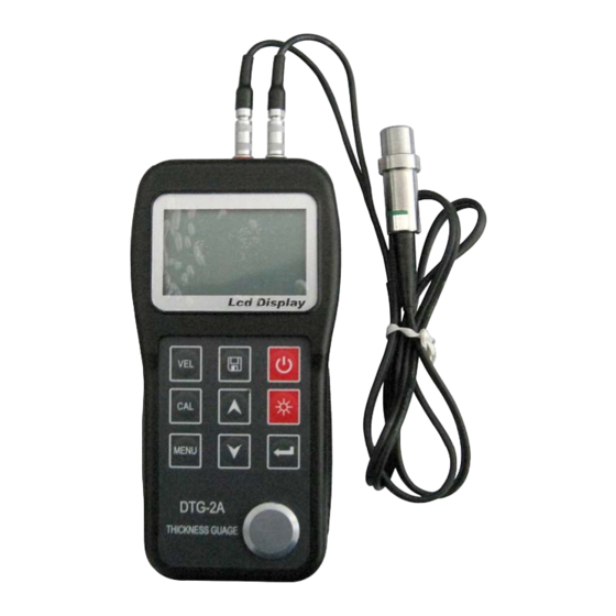
TDS-110 Ultrasonic Thickness Gauge 1.4 Appearance 1.5 Keyboard ☼ Power ON/OFF LCD backlight on/off sound velocity Save data / Browse data Calibration standard block of 4.00mm MENU Function selector Adjusting sound velocity and thickness; key for moving menu cursor ... -
Page 6: Display Symbols
TDS-110 Ultrasonic Thickness Gauge 1.6 Display symbols 2 Product Specifications 2.1 Technology parameter Display: 128×64 LCD with LED backlight. Measuring range: 0.75mm~300.0mm (0.03inch~11.8 inch) Sound Velocity Range: 1000m/s~9999m/s (0.039~0.394in/µs Display resolution: 0.01mm or 0.1mm (lower than 100.0mm) 0.1mm (more than 99.99mm) -
Page 7: Main Functions
TDS-110 Ultrasonic Thickness Gauge 2.2 Main Functions 1) Capable of performing measurements on a wide range of material, including metals,plastic,ceramics,composites,epoxies,glass and other ultrasonic wave well-conductive materials. 2) Transducer models are available for special application,including for coarse grain material and high temperature applications. -
Page 8: Setting Probe Frequency
TDS-110 Ultrasonic Thickness Gauge 3.3 Setting probe frequency Press MENU key to move the cursor to the position as that shown in the following figure. Press to change the frequency setting. LCD will display in sequence the probe frequency to be set 5M, 7M or ZW. -
Page 9: Setting Alarm Thickness Limits
TDS-110 Ultrasonic Thickness Gauge actual thickness with , press VEL, now it will display the sound velocity to be measured. Save the value into current sound velocity memory unit. For measuring sound velocity, one must select a test piece with adequate thickness, and the recommended min. -
Page 10: System Setup
TDS-110 Ultrasonic Thickness Gauge 3.7.1 System Setup Measurement units: metric and Imperial Receiving gain: LOW and HIGH 1. The LOW is mainly used for measuring coarse material with high scatter and small sound absorption, such as cast aluminum, cast copper and other metallic parts. - Page 11 TDS-110 Ultrasonic Thickness Gauge out a moment ago, and the MIN indicator for the minimum value will flash several seconds. If you continue the measurement when the MIN is flashing, the former measurements will continue to take part in the min. value capturing. If you carry out measurement after MIN indicator stops flashing, the min.
-
Page 12: Print Function
TDS-110 Ultrasonic Thickness Gauge 2. Use to adjust the display brightness. 3. Press exit setup. 3.7.2 Print function Connect main unit with micro printer from by the communication cable, print measured results through menu selection. When the printing is completed, the buzzer will give out sound, the display will return to MENU state. -
Page 13: Data Logger Operation
TDS-110 Ultrasonic Thickness Gauge 4 Data logger operation 4.1 Logging readings into memory The instrument divides the memory unit into 5 files. Each can save 100 measurement values. Before saving data, Please set file number first. If you select the current file No., you can save the measurement directly by pressing The procedures for setting file No. -
Page 14: Measuring Technology
TDS-110 Ultrasonic Thickness Gauge 5. Measuring technology 5.1 Cleaning surface Before measuring, please clean any dust, dirt and rust on the object, and remove any cover such as paint, etc. on it. 5.2 Improving requirement on roughness Too rough surface will cause error in measurement. Before measuring, please smooth the surface of object by grinding, polishing or filing, etc. -
Page 15: Un-Parallel Surface
TDS-110 Ultrasonic Thickness Gauge 5.6 Un-parallel surface To get a satisfactory ultrasonic response, the other surface of the object must be parallel to or co-axial with the surface to be measured, otherwise, it will cause measuring error or even no display. -
Page 16: Several Measuring Methods
TDS-110 Ultrasonic Thickness Gauge that of the object, and the transmitting direction of sound wave in it should also be same as that for the object. Under certain circumstances, look up the speed-of-sound table for given materials can replace reference test pieces. But this is approximately to substitute some test pieces. -
Page 17: Measuring Casting
TDS-110 Ultrasonic Thickness Gauge 5.13 Measuring casting It has specialty for measuring casting. The crystal particles for castings are coarse, the structures are not dense enough, plus that they are in gross state, which makes difficulty in measuring their thickness. -
Page 18: Rust, Corrosion And Pit
TDS-110 Ultrasonic Thickness Gauge measured value is larger than the actual thickness. To prevent these kinds of errors, please repeat the measurement to check the results. 6.2 Rust, Corrosion and Pit The rust and pit on the other surface of the object will cause irregular change in readouts. -
Page 19: Attention
TDS-110 Ultrasonic Thickness Gauge cause error or flashing coupling indicator, and it will be impossible to measure. The coupling agent should be used in proper amount and be coated evenly. It is very important to select proper coupling agent. When it is used on a smooth surface, you’d better use an agent with low viscosity (such as coupling agent... -
Page 20: Absolutely Avoid Collision And Moisture
TDS-110 Ultrasonic Thickness Gauge 7.5 Absolutely avoid collision and moisture. 8. Maintenance When the error of measurement is too large, please refer to chapter 6, 7. If the following problems occur, please contact the Maintenance Department of Time Group: a. The component of the instrument is damaged and it is impossible to measure. -
Page 21: Configuration
TDS-110 Ultrasonic Thickness Gauge 9.Configuration ITEM QUANTITY NOTE Main Unit Transducer Couplant Standard Instrument case configuration Operating Manual 1.5V battery Transducer:N02 Transducer:N07 Transducer:HT5 Mini Thermal printer Optional Print cable Configuration DataPro Software Communication cable... -
Page 22: Appendix Ⅰ
TDS-110 Ultrasonic Thickness Gauge Appendix Ⅰ Sound velocity for Different Materials Sound velocity Material (m/s) (inch/µs) Aluminum 6320-6400 0.250 Zinc 4170 0.164 Silver 3607 0.142 Gold 3251 0.128 2960 0.117 Steel,common 5920 0.233 Steel,stainless 5740 0.226 Brass 4399 0.173 Copper 4720 0.186...
Need help?
Do you have a question about the TDS-110 and is the answer not in the manual?
Questions and answers