Table of Contents
Advertisement
Quick Links
Advertisement
Table of Contents

Related Manuals for Varme VT100C

Summary of Contents for Varme VT100C
- Page 1 VT100C USER MANUAL ENGLISH VT180C 967946-02...
-
Page 2: Table Of Contents
Information for the user Information for the installer General information For your own reference HP working principle TECHNICAL DATA CONSTRUCTION - VT100C CONSTRUCTION - VT180C INSTALLATION Choice of the installation location Other installation requirements GENERAL RULES FOR HYDRAULIC CONNECTION HYDRAULIC INSTALLATION... - Page 3 ENGLISH APPENDIX COOLING CIRCUIT Work princible DUCT CONNECTION EXTERNAL CONTROLLED DHW PRODUCTION Use of solar cell function Wiring of a solar cell installation Wiring recommendations Use of holiday function Use of boost function Use of external controlled DHW production Use of timer function SUPPLEMENTARY ELECTRICAL HEATING MAINTENANCE AND CARE Care by the end user...
-
Page 4: Congratulation
ENGLISH CONGRATULATION INFORMATION FOR THE USER GENERAL INFORMATION Congratulations for your choice. You have chosen high-end, The heat pump usually covers a family’s need for hot water high quality DHW HP, which will supply for you DHW throughout the year. economically and at the highest comfort level for a very long time. -
Page 5: Hp Working Principle
ENGLISH HP WORKING PRINCIPLE: The HP is the prioritized energy source for the generation of DHW. The heat pump operates according to the air to water principle: The energy is extracted from the ambient air in the evaporator. In order to ensure the energy supply, the air is forced through the evaporator by a powerful fan. -
Page 6: Technical Data
ENGLISH TECHNICAL DATA - VT100C COEFFICIENT OF PERFORMANCE ACCORDING TO EN16147:2017 20 °C - ambient air - 59,5% relative humidity Setpoint at controller unit 55 °C M profile 3,05 COP* Standby power dB(A) Acoustic emission (ducted) (according to EN 12102-1:2017 and EN ISO 9614-2) - Page 7 ENGLISH TECHNICAL DATA - VT180C COEFFICIENT OF PERFORMANCE ACCORDING TO EN16147:2017 20 °C - ambient air - 59,5% relative humidity Setpoint at controller unit 55 °C L profile 3,20 COP* Standby power dB(A) Acoustic emission (ducted) (according to EN 12102-1:2017 and EN ISO 9614-2) HEAT PUMP Dimensions Height: 1576 Width: 540 Depth: 575...
-
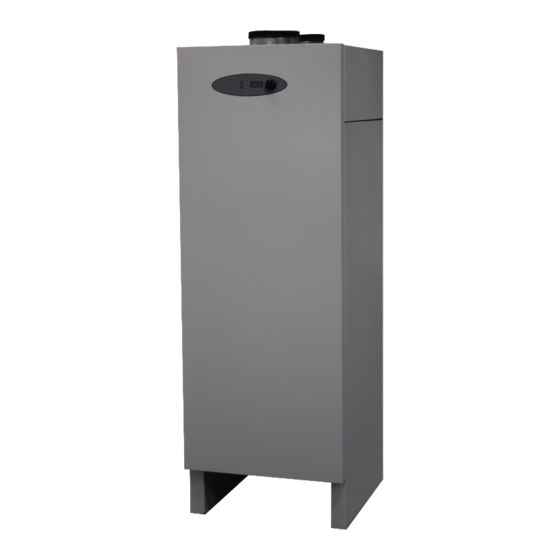
Page 8: Construction - Vt100C
ENGLISH CONSTRUCTION - VT100C COMPRESSOR COLD WATER INLET 3/4” BSP FEMALE DISPLAY UNIT AIR INLET (ø160mm) EVAPORATOR AIR OUTLET (ø160mm) OPERATING- / ALARM LED - HEAT PUMP ENAMELLED CONTAINER OPERATING- / ALARM LED - SUPPLEMENTARY HEATING CENSOR POCKET DISPLAY THERMOSTAT... -
Page 9: Construction - Vt180C
ENGLISH CONSTRUCTION - VT180C COMPRESSOR COLD WATER INLET 3/4” BSP FEMALE DISPLAY UNIT AIR INLET (ø160mm) EVAPORATOR AIR OUTLET (ø160mm) OPERATING- / ALARM LED - HEAT PUMP ENAMELLED CONTAINER OPERATING- / ALARM LED - SUPPLEMENTARY HEATING CENSOR POCKET DISPLAY THERMOSTAT CONTROL BUTTON HEATING ELEMENT CONTROLLER UNIT... -
Page 10: Installation
It has to support the weight of the DHW HP (approx. 200 Kg for VT100C and 300 Kg for VT180C filled). The location must be designed to support the corresponding load. If the HP will operate mostly on, off peak hours do not The heat pump can be installed install the product near to bedrooms. -
Page 11: Other Installation Requirements
1° to run out in a prober way. 90° Applicable for both VT100C and VT180C Defrost water tube must be mounted in correct level of the defrost water outlet of the heat pump and into the drainage. If... - Page 12 INSTALLER ONLY tank of water (see page 6 for weight information). When installing ductings the weight may not be If the customer wish to wall mount the VT100C heat pump supported onto the heat pump. please follow the below instructions carefully.
- Page 13 ENGLISH After mounting the 2 brackets on the wall. - Carefully pick up the heat pump and move towards the wall. - Slowly begin to lower the heat pump until it graps into the support bracket (1) and lands onto the lower bracket (2) - Before letting go of the heat pump be sure it has grapped into the support bracket (1) else the heat pump will turn forward.
-
Page 14: General Rules For Hydraulic Connection
ENGLISH GENERAL RULES FOR HYDRAULIC CONNECTION Your DHW HP has a high quality stainless steel tank for the The installation must be done according to the DHW production. In order to protect the tank and also the state of the art of installation. The non-respect of connectors you have to avoid connecting copper pipes or these rules and abnormal water composition may galvanized steel fittings directly. -
Page 15: Preparation For Installation
ENGLISH The DHW HP works either with ambient air or outside air The air must be dust and grease free. depending on which version of VT100C or VT180C you have acquired. The air source should benefit from free energy gains like in the laundry (dryer waste energy),... -
Page 16: Cold Water Connection Scheme
ENGLISH COLD WATER CONNECTION SCHEME 1: Cold water inlet The scheme is only a guideline. Always carry out piping according to local, national and/or 2: Ball valve 1”: must be open during operation. international legislations. 3: Dirt collector 1”: Collects rust and other unwanted particles from the pipe system. -
Page 17: Dhw Production
ENGLISH DHW PRODUCTION Your DHW HP can generate DHW with different energy Heating of domestic water can be made using the sources, such as HP and/or electrical heater (built-in) heat pump and/or electrical heater. Electrical heater (built-in), installation are referred The energy sources are selected in the menu. -
Page 18: Electrical Installation
ENGLISH ELECTRICAL INSTALLATION The heat pump is equipped with a 1,8 metre power The appliance must be installed in accordance supply cord, 3G x 1.5 mm2, which comes out on the bottom with national wiring regulations by a qualified and of the device with stress relief bushing and a safety plug. -
Page 19: User Interface
ENGLISH USER INTERFACE The upper line displays the parameter menu (function). 2-line display (control panel setup) The bottom line displays the parameter status or The display is activated (indicated) by turning or pressing the value. rotary-/push button (no. 32 on the control panel drawing). To scroll through the menu turn the rotary-/push button. - Page 20 ENGLISH Similar function as Tmin, used for “holiday function” or when the DHW HP is in “standby” mode. Tmin protects T2min the DHW HP and your installation against freezing. The factory setting is “10°C”. 10 °C Here the timer function can be selected. The following options are provided: Timer “ON”, “OFF”...
- Page 21 ENGLISH This function permits to operate the DHW HP with cheap and environmentally friendly energy from your own solar cell panels. SolarCel “OFF” = Solar cells are not connected to system or not chosen to be used by the user. “HP only”...
-
Page 22: Display View - Service Parameter Menu
This parameter displays the selected defrosting mode. Attention: The defrosting mode is model specific and must not be changed without written consent of the manufacturer. Defrost The possible selections are: “GAS” or “AIR” for VT100C and VT180C Service Def.None, Def.Gas, Def.Air “OFF”, “ON” Anode Is activated if signal anode is factory installed or can be activated if signal anode is retrofit. -
Page 23: Alarm Levels And Handling
ENGLISH ALARM LEVELS AND HANDLING There are 3 alarm levels. The display can show 3 different alarms at the same time. The alarm must be acknowledged and reset by pressing the rotary/push button. Alarm 0 0 0 Level 1 - The information alarm: does not affect the HP operating, but informs the user that there is a problem, which might need action and should be resolved as soon as possible. -
Page 24: Led Indicator Status
ENGLISH [Alarm mode] (Red LED) LED INDICATOR STATUS LED (17) Alarm for HP flashes red: Information- or coolant system alarm. 5 6 0 Both LED (17 + 18) flash: DHW HP alarm, no DHW production possible. ERROR NO. / DHW HP ALARMS / REMARK / ACTION LED INDICATOR POSSIBLE PROBLEM OR DEFECT... -
Page 25: Defrosting
DEFROSTING MODES The defrosting mode is model specific. “Defrost Gas” – Defrosting with hot gas. VT100C and VT180C with solenoid valve installed. “Defrost Air” - Defrosting with air. VT100C and VT180C without solenoid valve installed. DEFROSTING “GAS”... -
Page 26: Safety
ENGLISH SAFETY THERMAL DISINFECTION - Example! LEGIONELLA PROTECTION If legionella sequence is activated at 23:00 by user and a power cut The procedure must be activated in the parameter menu. happens during nighttime the sequence is deactivated and lost until next automatic If the legionella procedure is activated, the legionella sequence sequence. -
Page 27: Use Of Legionella Protection
ENGLISH USE OF THE LEGIONELLA PROTECTION New software version with the new legionella function. (Version 1.58 - 1.65) To check the software version you must go into installers menu, hold the rotary button for some seconds and the Software software version will appear. 1.58 User menu: use the rotary button to scroll to the legionella menu. - Page 28 ENGLISH User menu: Due to the high quality of In the “Water” status menu the user can see when the 60 °C, +-1 °C in hysteresis has been the insulation you will reached and the upper LED turns orange for experince that the hot water “standby”...
- Page 29 ENGLISH User menu: Status Use the rotary button to scroll to “Status” menu and note Le.Work that a user information is shown “Le.Work”. This tells that the legionella sequence is in progress. User menu: In the “Water” status menu the user can see when the 60 °C, +-1 °C in hysteresis has been reached and the up- per LED turns orange for “standby”...
- Page 30 ENGLISH User menu: In the “status” menu the user can see the information “H.Water” which tells that the heat pump is running in Status normal operating mode when the legionella alarm is H.Water activated. User menu: The user can push the button on the “Alarm” menu to Alarm acknowledge the alarm.
-
Page 31: Safety Valve, Contra Valve, Condensation Drain - The Installer
ENGLISH SAFETY VALVE, CONTRA VALVE, HOT WATER CONNECTION SCHEME CONDENSATION DRAIN – THE INSTALLER 1: Hot water outlet from heat pump The DHW HP tank must be protected by a safety valve and a contra valve on the cold water side. This is to protect the DHW 2: Ball valve 1”: must be open during operation. -
Page 32: Cooling Circuit
If air inlet and outlet is within the same room and ambient air temperature doesn’t go below +5°C you can use the VT100C and VT180C as an +5°C unit else use an -10°C unit. (Air / fan defrosting mode only) or... - Page 33 (Solenoid valve, hot gas defrosting mode) If air inlet is taken from another room and air outlet goes out then use the VT100C and VT180C as an +5°C unit as long as the ambient air temperature doesn’t go below +5°C else use an -10°C unit.
-
Page 34: External Controlled Dhw Production
ENGLISH EXTERNAL CONTROLLED DHW PRODUCTION USE OF SOLAR CELL FUNCTION The wiring of the controller determines the operating mode. You can operate your DHW HP environmentally friendly and economically with energy generated by your photovoltaic solar cell installation. This operation mode uses an increased If the solar function is deactivated, it will change to normal setpoint temperature, which can be individually selected and operation mode. -
Page 35: Use Of Holiday Function
ENGLISH USE OF HOLIDAY FUNCTION There will be an uncertainty of -+3% With the use of the holiday function you are able to lower when using manually setting of days. the power consumption during your holiday and absence from home. When activated, the hot water production will be 21 days = +- 0.6 days locked unless the DHW temperature is equal to “T2min”. -
Page 36: Use Of Timer Function
ENGLISH USE OF TIMER FUNCTION With use of software version 1.62 - 1.65 it is possible to use the timer function witin the software instead of an external installed timer/clock unit. Software 1.62 To check the software version you must go into installers menu, hold the rotary button for some seconds and the software version will appear. - Page 37 ENGLISH User menu: Use the rotary button to scroll to “ClockSet”. Press the ClockSet button until text is flashing and adjust the minutes to real time minutes, look at the household watch, and press the button again to acknowledge. User menu: Clock Scroll back to “Clock”...
- Page 38 ENGLISH User menu: To stop the timer function the user must set the stop minutes for when the heat pump should stop produce Stop HP hot water. Use the rotary button to scroll to “Stop HP” and press the button. The text will flash and rotate the button to adjust to desired stop minutes.
-
Page 39: Supplementary Electrical Heating
ENGLISH SUPPLEMENTARY ELECTRIC HEATING The upper part of the tank can be heated quickly by using the electrical heating element. The heating element is activated in the menu parameter “H.pump” selecting the value “EL” alone or with heat pump “HP + EL”. Tmin is set to the desired minimum temperature. -
Page 40: Maintenance And Care
ENGLISH MAINTENANCE AND CARE Your DHW HP is working automatically. Nevertheless it needs MAINTENANCE OF THE DRAIN some care and maintenance. We recommend to sign a service contract with your installer or to include it into an existing The discharge pipe of the heat pump must be connected to a service contract with your specialized service provider. -
Page 41: Spare Parts
ENGLISH SPARE PARTS Right to change of specification without prior notice reserved...
Need help?
Do you have a question about the VT100C and is the answer not in the manual?
Questions and answers