
Related Manuals for Aspen LCM-Twin T38


Summary of Contents for Aspen LCM-Twin T38
- Page 1 24 St. Martin Dr. Marlborough, MA 01752 Installation and Operation Instructions LCM-Twin T38 FP00066, FP00102 Installations Notes Date of Purchase Date of Installation Installer Model Number Serial Number...
-
Page 2: Table Of Contents
Customer Service ............................8 Commercial Product Warranty ......................... 8 Warranty Repairs ............................9 Technical Support ........................... 10 Aspen Contact Information ........................10 APPENDIX ..............................10 OM00017 Rev B, FP00066, FP00102 Operation Manual – March 24, 2023 Page 2 of 10... -
Page 3: System Information
The LCM also contains Polyalkylene glycol (PAG) oil, which is used by the compressor. Contact Aspen for the MSDS for either of these internal fluids. Precautions relating to the personnel hazards regarding contact with this substance should be outlined in training and technical manuals. -
Page 4: General Operation
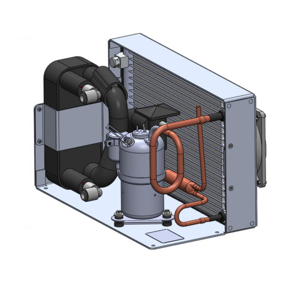
Two fans are attached to the condenser, which requires a 48 VDC (FP00066) or 24 VDC (FP00102) power supply. The provided fans each generates 138 cfm (without restriction). Aspen Systems does NOT recommend using the available voltage output on the compressor drive board to operate the fan. Please connect the fan directly to a 48 VDC supply (FP00066) or 24 VDC supply (FP00102). - Page 5 Airflow direction Airflow direction Figure 2: LCM Dimensional Drawing - Note all dimensions are in inches OM00017 Rev B, FP00066, FP00102 Operation Manual – March 24, 2023 Page 5 of 10...
-
Page 6: Power Supply - Fp00066 Only
43 VDC – 50 VDC. The LCM may draw up to 10.5 A of current during normal operation (compressor and fans combined). Aspen recommends at least 16 AWG wire for the power supply to the compressor drive board with an in-line 10 A fuse (see Appendix page 3) CAUTION! Operating the LCM outside the voltage range will void the system warranty. -
Page 7: Performance
CAUTION! Aspen recommends the following operating sequence: (1) power on the drive board, (2) ground the enable line (3) apply a speed signal to run the compressor. Applying power to the drive board while the enable line is grounded may result in high in-rush currents Note: In some conditions, the compressor will reach its nominal current limit. -
Page 8: Maintenance
If buyer claims that a product violates such warranty, Aspen, upon notice promptly given, will either examine the product at buyer’s site, or issue shipping instructions for return to Aspen at buyer’s expense, transportation charges prepaid. -
Page 9: Warranty Repairs
Aspen’s sole obligation under its warranty shall be, at its option, to repair, replace or refund the price of any product thereof which is proved to violate such warranty. In no event, whether based on contract, indemnity, warranty, tort (including negligence), strict liability or otherwise, shall Aspen be liable to the buyer for special, indirect, incidental or consequential damages whatsoever including, without limitation, loss of profit or revenue. -
Page 10: Technical Support
Technical Support Technical Support is available from Aspen Systems from 8:00 AM to 5:00 PM (EST) Monday through Friday via phone or email (see contact information). Technical support can also be requested on-line. To expedite assistance for problems, be able to provide the following information: •... - Page 11 Universal Low Noise Sinusoidal BLDC Drive Operating Instructions Aspen’s Universal Low Noise Sinusoidal BLDC Drive can be operated in 2 distinct modes. This allows it the ability to seamlessly replace all existing Aspen drives, as well as offer significant compressor noise reduction, lower compressor operational speeds and several different input types for speed control.
- Page 12 Drive Mode Jumper Jumper Mode 2 Universal Quiet Sinusoidal Not Installed Aspen Compressor, LLC 24 St. Martin Drive, Marlborough, MA 01752 508-281-5322 508-281-5323 web: email: www.aspencompressor.com info@aspencompressor.com Feb, 2023 Rev. D...
- Page 13 Aspen’s Universal Sinusoidal Low Noise Drive is available in 12, 24 and 48 volts. The use of adequate wire gage and an inline fuse for short circuit protection is required for safe reliable operation. The table below shows the recommended wire gage and input fuse size for each of the Aspen drives.
- Page 14 1. Condenser Fan Output (TB7 & TB8) An output has been provided for running condenser fan(s) from the Aspen drive. The voltage of this output will be equivalent to the DC input voltage provided to the board. The power to the condenser fan is enabled 10 seconds after the drive starts the compressor.
- Page 15 Jumper settings for these options can be found at the end of this section. Aspen Compressor, LLC 24 St. Martin Drive, Marlborough, MA 01752 508-281-5322 508-281-5323...
- Page 16 This tab should be used when a secondary power supply is being used to supply power for speed control and the user wants the secondary supply to be isolated from the power supply being used to power the Aspen Compressor, LLC 24 St. Martin Drive, Marlborough, MA 01752 508-281-5322 508-281-5323...
- Page 17 Additional Board Functions 1. Compressor Start Delay – The Aspen drive has the ability to delay the compressor start in situations where starting may be difficult due to an unbalanced system. The logic behind the delay is based on a minimum off time for the compressor and can be enabled by installing jumpers per the table at the end of this section.
- Page 18 5. Lock Rotor Protection - The Aspen drive has the ability to detect if the compressor is not running due to a lock rotor condition. After the drive has made several unsuccessful attempts to start the...
- Page 19 1501048 1501018 48 Volt 8 Amp The ramping speed of the compressor will also be reduced to further enhance sound reduction. Aspen Compressor, LLC 24 St. Martin Drive, Marlborough, MA 01752 508-281-5322 508-281-5323 web: email: www.aspencompressor.com info@aspencompressor.com Feb, 2023 Rev.
- Page 20 1501050 2.8 & 5.6cc T & H Series 48 Volt 10 Amp 1501052 3.8cc & 7.6cc T & H Series 48 Volt 10 Amp Aspen Compressor, LLC 24 St. Martin Drive, Marlborough, MA 01752 508-281-5322 508-281-5323 web: email: www.aspencompressor.com info@aspencompressor.com...
- Page 21 24v compressors and 8 amps for 48v 10 or 15 amps for 24v compressors and to 8 amps compressors. for 48v compressors. Aspen Compressor, LLC 24 St. Martin Drive, Marlborough, MA 01752 508-281-5322 508-281-5323 web: email: www.aspencompressor.com info@aspencompressor.com...
- Page 22 Mounting Diagram Compressor Wiring – The Aspen Universal Quiet Sinusoidal drive is supplied with a cable to attach the drive to the compressor. All other wiring is to be supplied by the end user. It is important to wire the compressor to the drive with the colors coded in the order per the picture below.
- Page 23 Universal Low Noise Sinusoidal BLDC Drive Typical Compressor Wiring Wiring with user supplied speed input voltage Typical Wiring Diagram Wiring with user supplied 20k potentiometer Aspen Compressor, LLC 24 St. Martin Drive, Marlborough, MA 01752 508-281-5322 508-281-5323 web: email: www.aspencompressor.com info@aspencompressor.com...
- Page 24 / pressure. 2. Liquid refrigerant being Limiting 2. Verify superheat to be between returned to the compressor. recommended 8-12 deg. F. Aspen Compressor, LLC 24 St. Martin Drive, Marlborough, MA 01752 508-281-5322 508-281-5323 web: email: www.aspencompressor.com info@aspencompressor.com Feb, 2023 Rev. D...
- Page 25 4 Flashes Repeating Board overheated 8 Flashes Repeating Compressor overheated 16 Flashes Repeating Compressor multiple stall over time 32 Flashes Repeating Aspen Compressor, LLC 24 St. Martin Drive, Marlborough, MA 01752 508-281-5322 508-281-5323 web: email: www.aspencompressor.com info@aspencompressor.com Feb, 2023 Rev. D...
Need help?
Do you have a question about the LCM-Twin T38 and is the answer not in the manual?
Questions and answers