
Related Manuals for AWG SWIMSMART SS110

Summary of Contents for AWG SWIMSMART SS110
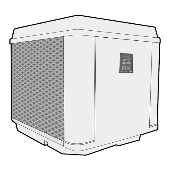
- Page 1 OWNER’S MANUAL Models: SS110 SS55 SS93 INSTALLATION, OPERATION MAINTENANCE & SERVICE SWIMSMART HEAT PUMPS BY AWG 888-475-7443 (HEAT)
- Page 2 WARNING: SAFETY CONSIDERATIONS • Qualified personnel should perform installation, maintenance and service. • Make sure all field wiring conforms to the heater specifications and all national and local codes. • Disconnect all power sources before performing any maintenance or service to the heater. INSPECTION Immediately upon receipt, inspect cartons and their contents for damage due to transit.
-
Page 3: Typical Installation
A. TYPICAL INSTALLATION SWIMSMART RETURN HEAT PUMP FROM WATER IN WATER OUT MAIN DRAIN / SKIMMER BALL VALVE FOR FLOW RATES CHLORINATOR GREATER THAN 50 G.P.M. OZONATOR PUMP FILTER B. INSTALLATION WITH A POOL AND SPA TO P/S ON HEAT PUMP SWIMSMART CONTROL HEAT PUMP... - Page 4 SS110 ELECTRICAL CONNECTIONS FOR 110V PLUG Disconnect all power sources before performing any work on unit. Field connections must comply with national and local codes. Plug only into a GFCI protected outlet Do NOT use extension cord to extend length of power cord GFCI outlet used for heat pump requires a 20 Amp breaker HEATER MUST BE PERMANENTLY GROUNDED AND BONDED.
-
Page 5: Service Disconnect
FIELD WIRING DIAGRAM FOR 220V HARDWIRE SERVICE DISCONNECT L1 L2 Compressor Contactor MAIN POWER GROUND Wiring External Controls and Remotes NOTE: When connecting remotes and external controls to the main control within the electrical enclosure, conduit must be used within the enclosure to ensure a definite separation of factory wiring/circuits and external control wiring. When installed ensure that there is no transmission of stress to main control wire terminal connections. - Page 6 WIRING DIAGRAM FOR 220V HARDWIRE 1. Use copper conductors only 2. Connect field wiring in grounded rain tight conduit, per rating plate. 3. Connect bond wire to pool steel using # 8 solid copper wire or larger. 4. All wiring must conform to National (N.E.C.) and local electrical codes. INDICATES FACTORY WIRING INDICATES FIELD WIRING...
-
Page 7: Electronic Control Panel
ELECTRONIC CONTROL PANEL DIGITAL DISPLAY LED INDICATORS POOL DISPLAYS WATER TEMPERATURE POOL & CURRENT MODE SETTING INDICATES POOL MODE ENGAGED POWER INDICATES COMPRESSOR IS ON SELECT KEY KEY OR SET POOL TEMP DOWN INDICATES SPA MODE IS ENGAGED SET SPA TEMP DOWN POOL OR SPA MODE POOL... -
Page 8: Initial Heating
START-UP Before proceeding with this section make certain all plumbing connections are airtight and leak free. Flow rates should not exceed 50 GPM maximum. Use of an external bypass is necessary at 50 GPM and above. Minimum flow rate is 15 GPM. Turn filter pump time clock to the ON position and set filter pump hours. -
Page 9: Defrost Cycle
DEFROST CYCLE The heat pump pool heater has automatic defrost. When the outdoor temperature drops below 40 °F, frost may start to form on the evaporator coil. Frost buildup will be heaviest on humid days when the temperature is between 35 and 40 ° F. During the defrost cycle, the display will show “DEF”... -
Page 10: Troubleshooting Checklist
WINTERIZING It is essential that all water within the unit be properly drained when winterizing your pool equipment. When water freezes, it expands, damaging piping. Turn thermostat settings to OFF. Turn filter pump to OFF. • Turn power to unit OFF (i.e. pull disconnect or turn circuit breaker OFF). •... -
Page 11: Calling For Service
A factory representative will assist you or your serviceman o ver the phone. 888-475-7443 SERVICE PERFORMED WITHIN THE WARRANTY PERIOD MUST BE APPROVED BY AQUACOMFORT PRIOR TO SERVICE BEING PERFORMED AND ONLY BY AN AWG AUTHORIZED TECHNICIAN. SEE WARRANTY FOR DETAILS. Please have the following ready before calling:... - Page 12 SWIMSMART HEAT PUMPS BY AWG 888-475-7443 (HEAT)
Need help?
Do you have a question about the SWIMSMART SS110 and is the answer not in the manual?
Questions and answers