Advertisement
Advertisement
Table of Contents

Summary of Contents for Recovent A22-1
- Page 1 USER’S MANUAL A22-1 Sensor control panel...
-
Page 2: Table Of Contents
Setup and control ..................................6 This user’s manual is a main operating document intended for technical, maintenance, and operating staff. The manual contains information about purpose, technical details, operating principle, design, and installation of the A22-1 unit and all its modifications. -
Page 3: Purpose
• When the unit generates unusual sounds, • Do not use damaged equipment or cables odour or emits smoke disconnect it from when connecting the unit to power mains. power supply and contact the Seller. • Do not touch the unit controls with wet •... -
Page 4: Technical Data
A22-1 TECHNICAL DATA 82 mm 42.5 mm 13.5 mm 60 mm Power supply voltage [V] R 2 mm Maximum load current [A] 0.025 Cable type 4х0.25 mm Temperature range [˚С] +10...+45 Humidity range [%] 10 - 80 (no condensation) - Page 5 1. Install the mounting box. Wall flush mounting: prepare a wall opening, lay required Wall surface mounting: lay required wires and cables to the wires and cables to the installation place and install the installation place, bore the holes and fix the mounting box on mounting box.
-
Page 6: Setup And Control
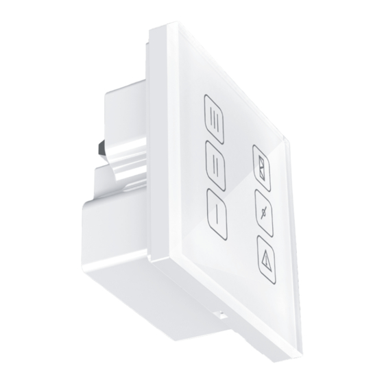
A22-1 6. Press the glass control panel of the control panel to the frame to click to fix it. SETUP AND CONTROL Addressing and parameters of RS-485 network The control panel is compatible with the following RS-485 network parameters: •... - Page 7 Indication and functions of the control panel buttons Speed 3 Filter maintenance Speed 2 Bypass mode Speed 1 Alarm indicator turn the unit on change speed stage press any inactive speed button. Once activated, the button starts glowing, and the ventilation unit runs with the set speed. turn the unit off press the active speed button.
- Page 8 Recovent55-9EN-02...
Need help?
Do you have a question about the A22-1 and is the answer not in the manual?
Questions and answers