Table of Contents
Advertisement
Quick Links
Operator's Manual
"Caution: Federal law restricts this device to sale or
rental by or on order of a physician, or any other
practitioner licensed by the law of the State in which
he/she practices to use or order the use of this device."
Dealer: This manual MUST be given to the end
user.
User: Before using this cylinder, read this
manual and save for future reference.
For more information regarding
Invacare products, parts, and services,
please visit www.invacare.com
HomeFill
Oxygen 540 Valve
HF2E540M9
Cylinder
®
Advertisement
Table of Contents

Subscribe to Our Youtube Channel
Related Manuals for Invacare HomeFill HF2E540M9

Summary of Contents for Invacare HomeFill HF2E540M9
- Page 1 HF2E540M9 “Caution: Federal law restricts this device to sale or rental by or on order of a physician, or any other practitioner licensed by the law of the State in which he/she practices to use or order the use of this device.” Dealer: This manual MUST be given to the end user. User: Before using this cylinder, read this manual and save for future reference. For more information regarding Invacare products, parts, and services, please visit www.invacare.com...
- Page 2 EQUIPMENT - OTHERWISE, INJURY OR DAMAGE MAY OCCUR. WARNING Invacare products are specifically designed and manufactured for use in conjunction with Invacare accessories. Accessories designed by other manufacturers have not been tested by Invacare. DANGER DO NOT SMOKE while using this device. Keep all...
-
Page 3: Table Of Contents
TABLE OF CONTENTS TABLE OF CONTENTS SPECIAL NOTES ..........4 RECEIVING INSPECTION ........4 INTENDED USE ..........4 SECTION 1—GENERAL GUIDELINES ....5 SECTION 2—FEATURES ........8 SECTION 3—TYPICAL PRODUCT PARAMETERS ..........9 SECTION 4—INSPECTION AND COMPRESSOR INTERFACE ........... 10 Cylinder Prefill Inspection ............... -
Page 4: Special Notes
SPECIAL NOTES SPECIAL NOTES Signal words are used in this manual and apply to hazards or unsafe practices which could result in personal injury or property damage. Refer to the following table for definitions of the signal words. SIGNAL WORD MEANING DANGER Danger indicates an imminently hazardous situation which, if not avoided, will result in death or serious injury. WARNING Warning indicates a potentially hazardous situation which, if not avoided, could result in death or serious injury. -
Page 5: Section 1-General Guidelines
SECTION 1—GENERAL GUIDELINES SECTION 1—GENERAL GUIDELINES WARNING SECTION 1 - GENERAL GUIDELINES contains important information for the safe operation and use of this product. DANGER This product is not intended as a life-sustaining or life-supporting device. WARNING Only personnel instructed and trained in the use of the HF2E540M9 Cylinder Assembly should operate this product. Product contains magnetic, ferrous material that may affect the results of an MRI. - Page 6 SECTION 1—GENERAL GUIDELINES WARNING DO NOT attempt to repair product. DO NOT immerse product in any kind of liquid. Store product in a clean area when not in use. Only use an Invacare Corporation HF2POST9BAG carrying bag. NEVER smoke in an area where oxygen is being administered. ALWAYS confirm prescribed dose before administering to patient and monitor on a frequent basis. DO NOT use if dirt or contaminants are present on or around cylinder, valve, product or connecting devices. NEVER use near any type of flame or flammable/explosive substances, vapors or atmosphere. ALWAYS follow ANSI and CGA standards for Medical Gas Products and Flowmeters (E‐7) and Oxygen Handling (G‐4). The use of this device is limited to the oxygen patient. Cylinders MUST be used only by the oxygen patient and are not to be distributed to any other individual for any purpose. DO NOT allow oil from your hands or other sources to come into contact with the cylinder fittings. These substances may become flammable in the presence of oxygen and cause injury. Avoid touching the cylinder fitting whenever possible. Example of items to avoid are hand creams or lotions, cooking oils, suntan oils or sunblocks and similar oily products. If you use these types of products Invacare suggests you wash your hands prior to using this product. If the cylinder fitting should come in contact with such substances it should be cleaned off with a damp cloth prior to connecting it to the compressor. HomeFill Cylinder Part No 1163156 ®...
- Page 7 SECTION 1—GENERAL GUIDELINES WARNING NEVER oil or lubricate the cylinder fittings. NEVER use any penetrating oil or lubricant such as WD‐40 or 3 in One. If connection difficulty is experienced verify that the cylinder fitting is being inserted straight down into the compressor coupler. If continued difficulty is experienced contact your supplier for assistance. DO NOT allow cylinders to tip or fall. Secure gas cylinders so they cannot fall. Ensure cylinder is always in upright position. DO NOT store cylinders near sources of heat or flame. DO NOT use while sleeping without consulting your healthcare provider. DO NOT place the unit under clothing while in use. When this product is in use a small amount of oxygen is vented. Wearing the unit under clothing may saturate fabrics with oxygen and cause them to burn rapidly if exposed to sparks or flame. It may take several hours for oxygen levels in fabrics to return to normal. Part No 1163156 HomeFill Cylinder ®...
-
Page 8: Section 2-Features
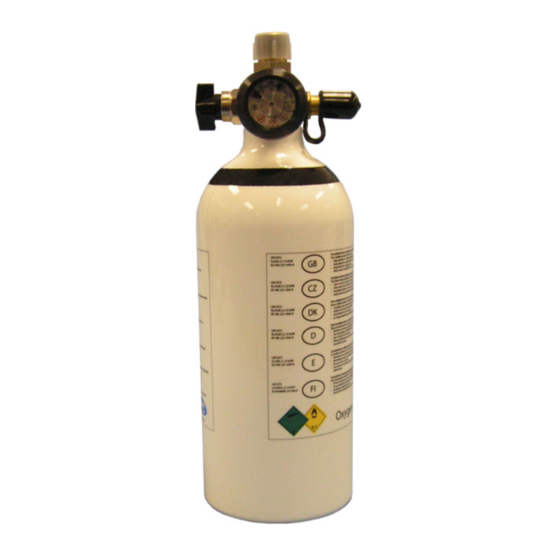
SECTION 2—FEATURES SECTION 2—FEATURES 540 Connection Port (with Protective Cap) Cylinder Cylinder Fill Valve Port FIGURE 2.1 Product Diagram HomeFill Cylinder Part No 1163156 ®... -
Page 9: Section 3-Typical Product Parameters
SECTION 3—TYPICAL PRODUCT PARAMETERS SECTION 3—TYPICAL PRODUCT PARAMETERS DIMENSIONS: Weight 5.1 lbs (2.31 kg) Overall Length 13.25 in (33.6 cm) Diameter 4.4 in (11.1 cm) STORAGE CONDITIONS TEMPERATURE: -40°F (-40°C) to 140°F (60°C) MAXIMUM HUMIDITY: Part No 1163156 HomeFill Cylinder ®... -
Page 10: Section 4-Inspection And Compressor Interface
SECTION 4—INSPECTION AND COMPRESSOR INTERFACE SECTION 4—INSPECTION AND COMPRESSOR INTERFACE NOTE: Refer to the HomeFill ® Compressor Owner’s Manual for compressor operating instructions. Cylinder Prefill Inspection WARNING All cylinders MUST be inspected before attempting to fill; otherwise, injury or damage may occur. NEVER smoke in an area where oxygen is being administered. - Page 11 SECTION 4—INSPECTION AND COMPRESSOR INTERFACE External Examination 1. Examine the outside of the cylinder for the following conditions and replace the cylinder if they exist: • Dents or dings • Arc burns • Oil or grease • Any other signs of damage that might cause a cylinder to be unacceptable or unsafe for use. 2. Examine the cylinder for evidence of fire or thermal damage. Evidence includes charring or blistering of the paint, or other protective coating or heat sensitive indicator. If fire or thermal damage is found, replace the cylinder. 3. Inspect the cylinder fillport for the following and replace if found: • Debris, oil or grease • Noticeable signs of damage • Signs of corrosion inside the valve • Signs of excessive heat or fire damage Part No 1163156 HomeFill Cylinder ®...
- Page 12 SECTION 4—INSPECTION AND COMPRESSOR INTERFACE Checking Cylinder Pressure WARNING NEVER use tools of any kind to connect/disconnect the cylinder and the compressor. Otherwise, severe injury and/or damage may occur. DO NOT drop oxygen cylinders. Use two hands when handling/transporting oxygen cylinders. Otherwise, injury or damage may occur.
-
Page 13: Filling The Cylinder
SECTION 4—INSPECTION AND COMPRESSOR INTERFACE Filling the Cylinder NOTE: For this procedure, refer to FIGURE 4.1 thru FIGURE 4.6. 1. Check the cylinder pressure before attempting to fill cylinder. Refer to Checking Cylinder Pressure on page 12. 2. Close the cylinder valve by rotating clockwise (FIGURE 4.1). 3. Remove the conserver or regulator according to the device manufacturer instructions (FIGURE 4.1). CONSERVER/REGULATOR CONSERVER/REGULATOR INSTALLED REMOVED Conserver/ Regulator Cylinder Valve Gauge Cylinder FIGURE 4.1 Component Identification 4. Remove the post valve cover (located on the cylinder) and the connector fillport covers (located on the compressor) (FIGURE 4.2). Part No 1163156 HomeFill Cylinder ®... - Page 14 SECTION 4—INSPECTION AND COMPRESSOR INTERFACE Connector Post Valve Cover Fillport Cover FIGURE 4.2 Fillport Covers 5. On the compressor unit, momentarily push DOWN on the outer ring (sleeve) of the connector fillport to reset the connector (FIGURE 4.3). HomeFill Cylinder Part No 1163156 ®...
- Page 15 SECTION 4—INSPECTION AND COMPRESSOR INTERFACE NOTE: If the outer ring (sleeve) is in the UP position (GREEN dots not visible), the connector fillport will not be able to accept the cylinder fillport. Pushing DOWN momentarily will reset the connector fillport (GREEN dots visible) to accept the cylinder fillport. PUSH Outer Ring (Sleeve) DOWN Connector Fillport GREEN Dots BEFORE COUPLING CYLINDER, PUSH DOWN ON SLEEVE UNTIL GREEN DOTS ARE VISIBLE. FIGURE 4.3 Resetting Connector Fillport 6. Grasp the cylinder assembly as shown in Detail “A” in FIGURE 4.4. 7. Position the cylinder in the compressor cradle as shown in Detail “C” in FIGURE 4.4.
- Page 16 SECTION 4—INSPECTION AND COMPRESSOR INTERFACE NOTE: Refer to Cylinder Fill Times on page 20 for the length of time it will take to fill the cylinder. DETAIL “B” DETAIL “A” Cylinder Cylinder Assembly Outer Ring Fillport (Sleeve) Compressor DETAIL “C” Power Switch Cylinder Outer Ring (Sleeve) Connector Compressor Cylinder PULL Fillport Cradle Fillport FIGURE 4.4 Connecting the Cylinder to the Compressor HomeFill Cylinder Part No 1163156...
- Page 17 SECTION 4—INSPECTION AND COMPRESSOR INTERFACE 11. After the cylinder is full, press the compressor power switch to the Off (O) position (FIGURE 4.5). 12. Grasp the cylinder assembly (FIGURE 4.5). 13. With the other hand, grasp the outer ring (sleeve) of the connector fillport and push DOWN (FIGURE 4.5). 14. Lift up on the cylinder assembly to remove from the connector fillport (FIGURE 4.5). PUSH DOWN Outer Ring (Sleeve) Cylinder Cylinder Fillport Assembly Power Switch Connector Compressor Fillport FIGURE 4.5 Disconnecting the Cylinder from the Compressor 15. When the cylinder fillport is disconnected from the connector fillport, release the outer ring (sleeve) of the ...
- Page 18 SECTION 4—INSPECTION AND COMPRESSOR INTERFACE WARNING The fillport cover on the connector fillport and the post valve fillport MUST be replaced after filling and whenever not in use. If either of the fillport covers are missing contact your healthcare provider before using. 17.
-
Page 19: Section 5-Maintenance
SECTION 5—MAINTENANCE SECTION 5—MAINTENANCE 1. After each use, clean exterior of the product with a dry, lint free cloth only. 2. Store product in a clean area free from grease, oil, and other sources of contamination. CAUTION DO NOT use cleaning solutions. DO NOT immerse product in any kind of liquid. All repairs MUST be done by Invacare Corporation. Part No 1163156 HomeFill Cylinder ®... -
Page 20: Section 6-Cylinder Fill Times
SECTION 6—CYLINDER FILL TIMES SECTION 6—CYLINDER FILL TIMES NOTE: All filling times are approximate and may vary on environmental conditions. Cylinder Filling Concentrator Flow Rate to Times Patient: (Platinum 5 up to 2.5 L/min and Platinum 10 up to 5 L/min) NORMAL 2 hr 20 min MAXIMUM 2 hr 45 min Troubleshooting If post valve cylinder fails to function, try the following ... - Page 21 NOTES NOTES Part No 1163156 HomeFill Cylinder ®...
-
Page 22: Limited Warranty
Upon receiving notice of an alleged defect in a product, Invacare will issue a serialized return authorization. It shall be the responsibility of the purchaser to pack the product(s) or part(s) in an appropriate manner to avoid shipping damage and return the product(s) or part(s), at the purchaser’s expense, to either... - Page 23 COMPONENT WITHOUT THE SPECIFIC CONSENT OF INVACARE; PRODUCTS DAMAGED BY CIRCUMSTANCES BEYOND INVACARE’S CONTROL; OR PRODUCTS REPAIRED BY ANYONE OTHER THAN INVACARE OR AN INVACARE SERVICE CENTER. SUCH EVALUATION SHALL BE SOLELY DETERMINED BY INVACARE. THE FOREGOING EXPRESS WARRANTY IS EXCLUSIVE...
- Page 24 All rights reserved. Trademarks are One Invacare Way identified by the symbols ™ and ®. Elyria, Ohio USA All trademarks are owned by or 44036-2125 licensed to Invacare Corporation or its 800-333-6900 subsidiaries unless otherwise noted. Technical Services © 2009 Invacare Corporation 800-832-4707...
Need help?
Do you have a question about the HomeFill HF2E540M9 and is the answer not in the manual?
Questions and answers