Table of Contents
Advertisement
Quick Links
OPERATING INSTRUCTIONS AND
SYSTEM DESCRIPTION OF THE
VA-10M
VOLTAMMETRIC AND
AMPEROMETRIC AMPLIFIER
FOR EPMS SYSTEMS
VERSION 4.2
npi 2017
npi electronic GmbH, Bauhofring 16, D-71732 Tamm, Germany
Phone +49 (0)7141-9730230; Fax: +49 (0)7141-9730240
support@npielectronic.com; http://www.npielectronic.com
Advertisement
Table of Contents

Summary of Contents for NPI VA-10M
- Page 1 OPERATING INSTRUCTIONS AND SYSTEM DESCRIPTION OF THE VA-10M VOLTAMMETRIC AND AMPEROMETRIC AMPLIFIER FOR EPMS SYSTEMS VERSION 4.2 npi 2017 npi electronic GmbH, Bauhofring 16, D-71732 Tamm, Germany Phone +49 (0)7141-9730230; Fax: +49 (0)7141-9730240 support@npielectronic.com; http://www.npielectronic.com...
-
Page 2: Table Of Contents
6.1. Headstage Elements ..................... 12 7. Operation .......................... 13 7.1. Setting up the VA-10M ....................13 7.2. Testing Basic Functions of the VA-10M ..............14 Open Circuit Test ......................14 DC Accuracy ....................... 14 Dynamic Test / Frequency Response ................15 7.3. -
Page 3: Safety Regulations
(e.g. for diagnosis or treatment of humans), or for any other life-supporting system. npi electronic disclaims any warranties for such purpose. Equipment supplied by npi electronic must be operated only by selected, trained and adequately instructed personnel. -
Page 4: Epms-07 Modular Plug-In System
2. EPMS-07 Modular Plug-In System 2.1. General System Description / Operation The npi EPMS-07 is a modular system for processing of bioelectrical signals in electrophysiology. The system is housed in a 19” rackmount cabinet (3U) has room for up to 7 plug-in units. -
Page 5: Epms-03
Note: The chassis of the PWR-03D is connected to protective earth, and it provides protective earth to the EPMS-E housing if connected. Figure 3: Left: PWR-03D front panel view Right: PWR-03D rear panel view. Note: This power supply is intended to be used with npi EPMS-E systems only. version 4.2 page 5... -
Page 6: System Grounding
VA-10M User Manual 2.7. System Grounding EPMS-07/EPMS-03 The 19" cabinet is grounded by the power cable through the ground pin of the mains connector (= protective earth). In order to avoid ground loops the internal ground is isolated from the protective earth. -
Page 7: Introduction
VA-10M User Manual 3. Introduction Recently, electrochemical methods using carbon-fiber microelectrodes have been applied to measure the release of oxidizable transmitter from single cells, and, even more impressively, from single exocytotic vesicles. Transmitters that are oxidizable and which, therefore, can be measured with this approach, include serotonin, dopamine, adrenaline, and noradrenaline. -
Page 8: Va-10M Components
10 µM or less from single cells plated onto glass cover slips. However, it can also be used for measurements made on superficially located cells in tissue slices. The VA-10M is not recommended for use in in vivo recordings with carbon-fiber electrodes having long cylindrical measuring surfaces, because in this case currents approach the µA range and a third... -
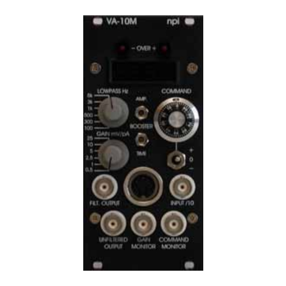
Page 9: Description Of The Front Panel
VA-10M User Manual 5.2. Description of the Front Panel Figure 5: VA-10M front panel view In the following description of the front panel elements each element has a number that is related to that in Figure 5. The number is followed by the name (in uppercase letters) written on the front panel and the type of the element (in lowercase letters). - Page 10 VA-10M User Manual (1) UNFILTERED OUTPUT connector BNC connector providing an unfiltered voltage proportional to the current passed through the electrode. The signal is amplified by the GAIN factor selected by switch (3). (2) FILT. OUTPUT connector BNC connector providing a filtered voltage proportional to the current passed through the electrode.
- Page 11 (8) +/0/- switch Switch to set the polarity of the COMMAND voltage. In position 0 the COMMAND voltage generated by the VA-10M is disabled. (9) INPUT /10 connector BNC connector to connect an external waveform for fast cyclic voltammetry. The INPUT voltage is divided by 10 internally and applied to the electrode.
-
Page 12: Headstage
VA-10M User Manual 6. Headstage The VA-10M comes with the standard headstage (range: 1000 mV) for connecting carbon- fiber electrodes via an electrode holder (optional). A 3-electrode headstage with differential input (see also Optional accessories in chapter 4) is also available. For details contact npi. -
Page 13: Operation
7. Operation 7.1. Setting up the VA-10M The VA-10M EPMS amplifier is shipped as a plug-in unit for the EPMS-07 modular system and equipped with a small headstage with a BNC connector. When the system arrives the headstage will not be connected to the cabinet. -
Page 14: Testing Basic Functions Of The Va-10M
LCD in mV. This voltage is applied to the electrode mounted on the headstage. If you intend to read the signal from the VA-10M into a data acquisition system, connect a BNC cable from the acquisition system to FILT. OUTPUT (#2, Figure 5) or UNFILTERED OUTPUT (#1, Figure 5). -
Page 15: Dynamic Test / Frequency Response
VA-10M User Manual Apply a command signal of 100 mV DC to the headstage from the COMMAND setting of the voltammeter. Alternatively, connect a DC signal of 1 V to the INPUT /10 BNC connector. Important: If an external voltage source is used, the 3-position toggle switch controlling the internal voltage source (#8) should be set to “0”. -
Page 16: Carbon-Fiber Electrodes
For this application, it is necessary to use an external voltage source connected to the INPUT /10 connector (#9, Figure 5) at the front panel of the VA-10M. Because one has to relate the measured current to the applied instantaneous voltage, the current and the applied voltage should be recorded simultaneously with a data acquisition system. -
Page 17: Literature
VA-10M User Manual 8. Literature VA-10 typical recordings Bai, J., Wang, C. T., Richards, D. A., Jackson, M. B., & Chapman, E. R. (2004). Fusion pore dynamics are regulated by synaptotagmin*t-SNARE interactions. Neuron 41, 929-942. Barclay, J. W., Craig, T. J., Fisher, R. J., Ciufo, L. F., Evans, G. J., Morgan, A., & Burgoyne, R. - Page 18 VA-10M User Manual Jaffe, E. H, Marty, A., Schulte, A. and Chow, R.H. (1998). Extrasynaptic vesicular transmitter release from the somata of substantia nigra neurons in rat midbrain slices. J.Neurosci. 18, 3548-3553. Lerner, I., Trus, M., Cohen, R., Yizhar, O., Nussinovitch, I., & Atlas, D. (2006). Ion interaction at the pore of Lc-type Ca2+ channel is sufficient to mediate depolarization- induced exocytosis.
- Page 19 VA-10M User Manual Marinesco, S., Wickremasinghe, N., & Carew, T. J. (2006). Regulation of behavioral and synaptic plasticity by serotonin release within local modulatory fields in the CNS of Aplysia. J Neurosci. 26, 12682-12693. VA-10 used for recordings with electrode arrays ...
- Page 20 VA-10M User Manual References (methods) Alvarez de Toledo, G., Fernandez-Chacon, R., & Fernandez, J. M. (1993). Release of secretory products during transient vesicle fusion. Nature 363, 554-557. Chow, R. H., von Rüden, L., & Neher, E. (1992). Delay in vesicle fusion revealed by electrochemical monitoring of single secretory events in adrenal chromaffin cells.
-
Page 21: Technical Data
VA-10M User Manual 9. Technical Data Headstage: Input voltage range: ±1200 mV Operating voltage: ±12 V Enclosure: Size: 40 x 70 x 20 mm, driven shield (COMMAND potential) mounting plate: 50 x 70 mm, not conducting Electrode connector: BNC with driven shield (COMMAND potential) -
Page 22: Va-10M With 3-Electrode Headstage
VA-10M User Manual VA-10M with 3-Electrode Headstage The 3-electrode headstage differs from the standard headstage in having an additional 1 mm electrode connector (REFERENCE) between the GROUND and COMMAND connectors for measuring the bath potential. This signal is processed electronically, so that the command potential is floating with respect to the bath potential.
Need help?
Do you have a question about the VA-10M and is the answer not in the manual?
Questions and answers