Table of Contents
Advertisement
AIRDATA
MULTIMETER
ADM-870C
™
ELECTRONIC MICROMANOMETER
WITH RS232 COMMUNICATIONS PORT
• AIR FLOW • VELOCITY • PRESSURE • TEMPERATURE •
OPERATING INSTRUCTIONS
S
Shortridge Instruments, Inc.
i
7855 East Redfield Road / Scottsdale, Arizona 85260-3430
Phone (480) 991-6744 • Fax (480) 443-1267
®
www.shortridge.com
ADM-870C 07/14/09
Advertisement
Table of Contents

Related Manuals for Shortridge Instruments AIRDATA ADM-870C


Summary of Contents for Shortridge Instruments AIRDATA ADM-870C
- Page 1 ™ ELECTRONIC MICROMANOMETER WITH RS232 COMMUNICATIONS PORT • AIR FLOW • VELOCITY • PRESSURE • TEMPERATURE • OPERATING INSTRUCTIONS Shortridge Instruments, Inc. 7855 East Redfield Road / Scottsdale, Arizona 85260-3430 Phone (480) 991-6744 • Fax (480) 443-1267 ® www.shortridge.com ADM-870C 07/14/09...
-
Page 2: Table Of Contents
CONTENTS 1.0 INTRODUCTION 1.1 GENERAL DISCUSSION 2.0 SPECIFICATIONS 3.0 EXTERNAL FEATURES 3.1 KEYPAD 3.2 FEATURES ON SIDES AND BACK OF METER 4.0 DISPLAY MESSAGES AND PROMPTS 4.1 READ PROMPTS 4.2 MEASUREMENT READOUTS 4.3 FUNCTION READOUTS 5.0 USING THE AIRDATA MULTIMETER 5.1 GENERAL USE 5.2 AUTOMATIC READINGS 5.3 TREND READINGS... - Page 3 REPLACEMENT PARTS LIST INDEX Copyright © Shortridge Instruments, Inc., 2009. All rights reserved. This information may not be reproduced or duplicated in any manner, or for any purpose, without permission in writing from Shortridge Instruments, Inc. Addendums or revisions made to this manual after July 2009 may be found at www.shortridge.com.
- Page 4 ILLUSTRATIONS 3.1 ADM-870C METER FRONT AND BACK 6.1 DWYER SERIES 160 STANDARD PITOT TUBE 6.2 AIRFOIL PROBE 6.3 VELGRID ASSEMBLY 7.1 STATIC PRESSURE PROBE 8.1 ADT442 TEMPROBE 8.2 AIRDATA MULTITEMP 10.1 FRAME STORAGE 10.2 FLOWHOOD IN CASE 10.3 FLOWHOOD ASSEMBLY 10.4 2X2 FRAME ASSEMBLY 10.5 1X4 FRAME ASSEMBLY 10.6 2X4 FRAME ASSEMBLY...
-
Page 5: Introduction
1.0 INTRODUCTION 1.1 GENERAL DISCUSSION You will find these instructions much easier to follow if you have the meter in front of you as you read through them. You can note the various connections and press the keys, observing the displayed results as you read through the various procedures. -
Page 6: Specifications
The measurement range is 25 to 29,000 fpm with a Dwyer Series 160 standard pitot tube, and 25 to 5,000 fpm with the Shortridge Instruments, Inc. AirFoil probe. The measurement range using the VelGrid is 25 to 2500 fpm. Accuracy is ± 3% of reading ± 7 fpm from 50 to 8000 fpm. Pitot tube velocity readings from 8,000 fpm to 29,000 fpm are based on compressible isentropic flow theory and are not certified NIST traceable. - Page 7 NOTE: A battery charge level displayed when the meter is first turned on may not be representative of the true level of battery charge. Wait five or ten minutes after turning the meter on to view the charge status. BATTERY CHARGERS: The battery charger (P/N PS8201) used in the U.S.A. and many other countries requires 120 Volts AC, 60Hz, 8W.
-
Page 8: External Features
3.0 EXTERNAL FEATURES 3.1 KEYPAD The meter keypad has eight keys, each of which may include multiple functions. Functions are activated by pressing a function key once, twice or in sequence with other keys. This Instruction Manual will often refer to a key by only one of the functions shown on the key. - Page 9 velocity measurements. A retractile cord connects the TemProbe or the MultiTemp to the temperature input jack for remote temperature sensing. RESET SWITCH The reset pushbutton switch is on the back of the meter in a recess near the upper left corner. This switch is used to reset the meter in the unlikely event that the microprocessor becomes lost in its program.
-
Page 10: Adm-870C Meter Front And Back
External Read Jack for 10 Digit, 0.4" LCD Display Pushbutton Handle Plug SHIFT Activates Upper Half of Keys DENS Local/Standard Density MODE Flow/Press/Temp/VLG/AFP/Pitot Battery Charger Jack RS232 Serial Port Jack UNITS English/Metric ASSOC Associated Press & Temp GRN LED Indicates if charger is plugged in CLEAR Clear Memory/Auto/Trend STORE... -
Page 11: Display Messages And Prompts
4.0 DISPLAY MESSAGES AND PROMPTS 4.1 READ PROMPTS The following ten prompts all include the term READ, which is a signal for the operator to press the READ key to trigger the actual measurement. English Units READ This display indicates that the meter has been placed in the air flow function (cfm) and will appear automatically upon power up if the flaps plug of the FlowHood is connected to the meter. -
Page 12: Function Readouts
IN ± n.nnnn Indicates that the result represents a differential pressure measurement (in wc). Metric Units Bar n.nnn Indicates that the result represents an absolute pressure measurement (bar). (One bar = 100 kPa). C ± nnn.n Indicates that the displayed result represents a temperature measurement ( LSc ±... - Page 13 c nnnn This message indicates a backpressure compensated air flow reading is being viewed in memory. The display shows the reading and its order in the reading sequence during a manual STORE sequence. Accessed using the RECALL keys. u nnnn This message indicates a nonbackpressure compensated air flow reading is being viewed in memory.
- Page 14 xx ` n.nnnn This display indicates that the meter is in TREND mode and that the readings are decreasing slowly. xx indicates the units for the reading. xx 9 n.nnnn This display indicates that the meter is in TREND mode and that the readings are decreasing rapidly. xx indicates the units for the reading.
- Page 15 AUTO ZERO When the meter is first turned ON, it will perform a self-calibration process that takes a few seconds. The display will read AUTO ZERO during this period and the operating controls will be inhibited. No READ operations or function changes may be made during the AUTO ZERO period.
- Page 16 FLOW ONLY FLOW ONLY will be displayed if the operator inserts the FlowHood flaps plug while the meter is in a velocity or differential pressure mode and presses the READ key. HALT This message will be displayed when an automatic reading, automatic reading storage, or TREND mode sequence has been halted manually by holding down the READ key.
- Page 17 NO LIGHT/BATTERY/TOO LOW This sequence of messages indicates that the battery charge is low and the back-light may not be used until the batteries are recharged. NO PROBE This message appears when the operator has neglected to install the TemProbe sensor prior to initiating a temperature measurement.
- Page 18 READING This message is displayed during differential pressure measurements, and also during the first reading period of some automatic reading sequences. It is also displayed during the manual reading which is taken when a sequence of TREND readings is halted. RECHARGE This message signals that the batteries have reached the end of their useful charge, and must be recharged.
- Page 19 will retain the readings in memory. The meter must be cooled down or warmed up, as the case may be, before normal operation can be resumed. If the meter has displayed OVER RANGE after displaying either TOO HOT or TOO COLD, but has not shut down, this message indicates that the TemProbe sensor was being exposed to temperature levels beyond the proper operating range.
-
Page 20: Using The Airdata Multimeter
5.0 USING THE AIRDATA MULTIMETER 5.1 GENERAL USE The ADM-870C keypad has eight keys, five of which are dual-purpose keys. The dual-purpose keys are OFF/ON, AUTO/READ, CLEAR/STORE, UNITS/ASSOC, and DENS/MODE. The functions shown in the lower, dark colored section of each key may be activated by pressing the desired key. The functions in the upper, silver colored sections of the keys are accessed by first pressing the SHIFT key, then the key of the desired function. -
Page 21: Automatic Readings
normally shown following the units for a displayed reading will be replaced by a symbol for an empty battery cell. The user will have 5 to 10 minutes of runtime before the meter displays RECHARGE/SHUT DOWN and turns itself off. The batteries must be recharged prior to further use. -
Page 22: Recall
displayed as nn nn, where nn is the sequence number of the reading and nn is the actual reading. Subsequent readings will be displayed in succession. The reading and memory entry process will continue as long as the READ key is pressed (up to a maximum of 200 readings). -
Page 23: Automatic Reading Memory
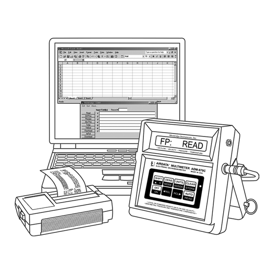
Readings may be downloaded directly from the meter to a printer, either as individual readings or multiple readings from memory. Shortridge Instruments, Inc. supplies the Seiko™ model DPU-H245, a palm-sized, portable printer which uses rechargeable batteries. Other compatible printers may also be used. -
Page 24: Download Automatic Readings To A Printer
5.6.2 DOWNLOAD AUTOMATIC READINGS TO A PRINTER Turn the printer on and then turn the meter on. The mode and units saved by the meter during the most recent use will be printed. Select the desired mode and units and then press SHIFT/AUTO to place the meter in the automatic reading mode. Press the READ key. -
Page 25: Data Download To A Computer
5.7 DATA DOWNLOAD TO A COMPUTER Readings from the ADM-870C AirData Multimeter may be automatically transmitted to specific cells of a computer spreadsheet such as Microsoft Excel™ for display, analysis and manipulation. This functionality requires either HyperTerminal Private Edition or WinWedge software from TAL Technologies, Inc. as well as an RS232 serial cable. The procedure using HyperTerminal is included on a CD supplied with the ADM-870C AirData Multimeter. -
Page 26: Port And Data Input Settings
The number and type of fields which are downloaded from the meter into WinWedge, and therefore to the spreadsheet, depends on the type of measurement being taken. Possible fields include the measurement command type, measurement mode, density selection, standard temperature assumption, value of reading, and units. The user may require a download format that includes only certain fields. -
Page 27: Set-Up Connections And Open The Applications
5.7.4 SET-UP CONNECTIONS AND OPEN THE APPLICATIONS Load the WinWedge software onto the computer. Open the spreadsheet application first, then open the WinWedge window. Move and/or size the two application windows so they are adjacent or overlapping and both visible on the screen. This allows for optimal viewing of the applications and use of the cursor. -
Page 28: Automatic Repeat Readings Controlled By Winwedge
controlled with the mouse, and WinWedge will place the data even though the cursor is not showing on the spreadsheet. If the output is changed to a different spreadsheet application, it will be necessary to change the entries in the Send Keystrokes To dialog window. - Page 29 to locking up and experiencing other problems due to confusion between commands issued to the meter using the computer keyboard and commands issued to the meter using the meter keypad. This printer equivalent download method is not recommended. ADM-870C 07/14/09...
-
Page 30: Velocity Measurement
6.0 VELOCITY MEASUREMENT Air velocity measurements obtained with the AirData Multimeter are automatically corrected for the density effect of barometric pressure on the velocity readings. The TemProbe sensor must also be used to obtain readings corrected for the changes in density caused by the temperature of the air being measured. If the TemProbe has not been connected to the meter, STD 70 F or STD 21.1 C will be displayed during the calculation period, and all data will be processed using... -
Page 31: Pitot Tube Velocity Measurement
Calculate the effective average face velocity (fpm) by dividing the actual air flow measured in Step #2 (cfm) by the gross active face area (sq ft) calculated in Step #1. Measure the average face velocity at the AMD using the VelGrid, AirFoil probe or other velocity instrument being tested for a Kv. -
Page 32: Airfoil Probe Velocity Measurement
FIGURE 6.1 DWYER SERIES 160 STANDARD PITOT TUBE Air flow within a duct may be calculated by multiplying the average duct air velocity (fpm) as measured with the pitot tube, by the duct area (sq ft). The resultant flow is expressed in cubic feet per minute (cfm). The standard pitot tube is .3125 inches in diameter and reduces the duct cross-sectional area by only 0.077 square inches in the measurement plane of the duct. -
Page 33: Duct Velocity Using Airfoil Probe
FIGURE 6.2 AIRFOIL PROBE The AirFoil probe lee side pressure port is not equivalent to the static pressure port on a pitot tube, and must not be used to obtain static pressure readings. 6.3.1 DUCT VELOCITY USING AIRFOIL PROBE The scribed rings on the AirFoil probe shaft are located at one inch increments from the tip orifice, and are provided to assist in controlling the probe measurement depth during duct velocity readings. -
Page 34: Laminar Flow Workstations - Airfoil Probe
of the exhaust hood. The equal area divisions are often set at 6" x 6", and seldom need to be set at less than 4" x 4". Each velocity sampling location should be at the center of an equal area division of the grid. All equal area divisions should be tested. -
Page 35: Chemical Exhaust Hoods - Velgrid
6.5.1 CHEMICAL EXHAUST HOODS - VELGRID The VelGrid provides the average of 16 measurement points at 3.5 inch centers, and represents a 14" x 14" area for each reading. When using the VelGrid for chemical exhaust hood readings, the sash opening must be set at a minimum opening of 14 inches in width for horizontal sliding sash, or 14 inches in height for vertically adjustable sash. -
Page 36: Velgrid Assembly
FIGURE 6.3 VELGRID ASSEMBLY ADM-870C 07/14/09... -
Page 37: Pressure Measurement
7.0 PRESSURE MEASUREMENT 7.1 DIFFERENTIAL PRESSURE Differential pressure measurements can be made with static pressure probes, a pitot tube or by connecting the pneumatic tubing directly to any appropriate pressure source within the safe operating limits for the meter. The manner in which a pitot tube is connected to the meter is critical to the type of differential pressure measurement obtained. -
Page 38: Pitot Tube "Total Pressures
(-) port exposed to the ambient pressure. Insert the pitot tube into the airstream as discussed under Section 7.1.2 PITOT TUBE VELOCITY PRESSURES above. The resulting pressure differential is recorded as static pressure. 7.1.4 PITOT TUBE "TOTAL PRESSURES" Total pressure measurements may be obtained using the pitot tube and the differential pressure mode by connecting the positive (+) port on the meter to the total pressure connection (in line with the main shaft) of the pitot tube and leaving the negative port of the meter exposed to the ambient pressure. -
Page 39: Temperature Measurement
8.0 TEMPERATURE MEASUREMENT 8.1 TEMPROBE Temperature measurements are obtained using the TemProbe temperature probe. The TemProbe may be plugged directly into the temperature input jack on the back of the meter. Since this receptacle is keyed, the plug of the TemProbe sensor must be correctly aligned for proper insertion. -
Page 40: Airdata Multitemp
readings as needed for any of the switch positions. Press the READ key to halt the reading process prior to changing switch positions. Changing switch positions during the actual reading process will cause false readings. FIGURE 8.2 AIRDATA MULTITEMP The individual and automatic storage functions may also be used with the MultiTemp. Set the meter for the individual storage or automatic reading storage functions as needed. - Page 41 9.0 AIR FLOW MEASUREMENT 9.1 FLOWHOOD FUNCTION The AirData Multimeter utilizes the Series 8400 FlowHood Kit for backpressure compensated measurement of air flow. The FlowHood unit captures and directs the air flow from an outlet, or inlet, across the highly sensitive flow sensing manifold within the FlowHood base.
- Page 42 10.0 FLOWHOOD ASSEMBLY 10.1 UNPACKING The FlowHood case has been specifically designed for the most efficient storage and handling of the FlowHood unit and its accessories. Note the arrangement of the various items as you unpack the unit. Especially note the placement of the foam cushioning around the instrument, and the orientation of the meter face toward the side of the case.
- Page 43 shown in Figures 10.5 and 10.6. The 1'x5' top requires an 8.5" dowel extender at the bottom of each support dowel. The dowel end pins are to be inserted into the inner set of frame support cups as shown in Figure 10.7. The 3'x3' top requires dowel extenders added to both the top and bottom of the support dowels.
-
Page 44: Frame Storage
FIGURE 10.1 FRAME STORAGE FIGURE 10.2 FLOWHOOD IN CASE ADM-870C 07/14/09... -
Page 45: Flowhood Assembly
FIGURE 10.3 FLOWHOOD ASSEMBLY ADM-870C 07/14/09... -
Page 46: 2X2 Frame Assembly
FIGURE 10.4 2X2 FRAME ASSEMBLY FIGURE 10.5 1X4 FRAME ASSEMBLY FIGURE 10.6 2X4 FRAME ASSEMBLY ADM-870C 07/14/09... -
Page 47: 1X5 Frame Assembly
FIGURE 10.7 1X5 FRAME ASSEMBLY FIGURE 10.8 3X3 FRAME ASSEMBLY ADM-870C 07/14/09... - Page 48 11.0 FLOWHOOD OPERATING PROCEDURE The meter handle should be removed from the AirData Multimeter by unscrewing the captive fasteners on the sides. The meter is inserted into the recess in the FlowHood base, using the captive fastener inside the base to secure it. The two pneumatic tubes from the flow sensing grid attach to the pneumatic inlets on the meter.
- Page 49 system to settle, then press the READ key to take the second (backpressure compensated) reading. If necessary, the FlowHood may be removed from the outlet in order to close the flaps. Position the FlowHood as before, and wait three seconds for the flow to stabilize before taking the second reading. The compensated reading will be displayed with a ‘c’ for compensated, as CF c nn.
- Page 50 12.0 SPECIAL BALANCING PROCEDURES 12.1 PROPORTIONAL BALANCING Backpressure compensated readings should be taken during the preliminary survey of the entire system with all dampers fully open, and also during the final reading after balancing is complete. Nonbackpressure compensated readings require less time and are usually adequate for the preliminary balancing of outlets.
- Page 51 12.5 LINEAR SLOT DIFFUSERS Linear slot diffusers deliver supply air in a sheet or air curtain that tends to follow the side of the cloth transition as it flows to the FlowHood base. This can result in an extremely uneven velocity distribution across the flow sensing grid when the flaps are open.
- Page 52 13.0 CORRECTION FACTORS 13.1 BAROMETRIC PRESSURE DENSITY CORRECTION The AirData Multimeter automatically corrects air flow and velocity readings to represent local density cfm or fpm as effected by barometric pressure. 13.2 TEMPERATURE DENSITY CORRECTION Air flow and velocity readings are density corrected for the effect of temperature if the TemProbe temperature sensor is used during flow or velocity measurements.
- Page 53 Local density velocity readings taken with the ADM-870C AirData Multimeter may be compared with hot wire anemometer readings if the hot wire readings are corrected for local air density conditions to obtain true air velocity results. The precise method for calculating local density corrected air velocity from measurements taken with a hot wire anemometer requires the use of the following equation: Where: = local barometric pressure (in Hg)
- Page 54 14.0 METER ACCURACY FIELD TESTING 14.1 METER ZERO FUNCTION Disconnect all tubing from the positive (+) and negative (-) ports of the meter. Perform several readings with the meter set for the flow or velocity mode, with no air passing across the meter ports. The meter should display zero readings, but may occasionally show a low reading such as 25 cfm or fpm.
- Page 55 14.5 DUCT TRAVERSE COMPARISON, INCLINED MANOMETER OR MICROMANOMETER An inclined manometer or standard micromanometer does not correct for density effects due to barometric pressure or temperature. The density correction necessary for duct traverse readings which are to be compared with FlowHood readings taken with the TemProbe in place is as follows: Where: P = local barometric pressure (in Hg)
- Page 56 15.0 METER MAINTENANCE The AirData Multimeter is a precision instrument designed for long term field use if given reasonable care and maintenance. The meter and FlowHood should be kept reasonably clean, and should be stored in the protective case when not in use. The meter case and internal components are rugged, and well able to withstand normal handling.
- Page 57 12" x 12" x 8" with sufficient additional cushioning to fill the carton. Do not use spray foam. Spray foam can damage the meter and it is also possible to “lose” a meter in a chunk of spray foam. Ship directly to: Shortridge Instruments, Inc. 7855 E. Redfield Rd. Scottsdale, Arizona 85260 Attention: Recalibration and Repair Dept.
- Page 58 Shortridge Instruments, Inc. reserves the right to make changes at any time, without notice, in prices, colors, materials, specifications and models, and also to discontinue models.
- Page 59 APPENDIX A - NIST VELOCITY TESTING The AirData Multimeter is primarily an electronic micromanometer which measures pressures very accurately. The velocity pressure generated by the various probes is used to calculate and display air velocity and air flow. Confirmation of the meter pressure measurement accuracy is fairly simple using NIST traceable transfer standard gages.
- Page 60 Some applications such as nuclear power plants, health care facilities and clean rooms require more frequent instrument calibration testing and accuracy verification. Calibration services and documentation is available at Shortridge Instruments, Inc. However, if interim calibration tests are required at your own metrology department or at an independent laboratory, the following information will be helpful.
- Page 61 APPENDIX C - BATTERY TEST PROCEDURE Insufficient battery charge (entire set or individual cells) can cause the meter to display garbled messages or TOO HOT, TOO COLD, RECHARGE or other messages. This garbled display usually is seen when the meter is just turned on and the supply voltage drops so fast that the meter gets lost.
- Page 62 Please call 1-800-822-8837 for information on Ni-Cd battery recycling and disposal bans/restrictions in your area. Shortridge Instruments, Inc. involvement in this program is part of our commitment to preserving our environment and conserving our natural resources.
-
Page 63: Adt442 Temprobe
ADM-870C REPLACEMENT PARTS LIST Part no No reqd per set Description ADM-870CM Advanced AirData Multimeter PS82 Battery charger PS8202 Battery charger for European use 0445 Plug adapter for use with PS8202 battery charger AA-NICAD Rechargeable Ni-Cd batteries ADT442 TemProbe temperature probe - 4" x 1/8" diameter TRC16 Temperature retractile cord - 1'x 6' TEW19... - Page 64 ADM-870C REPLACEMENT PARTS LIST (continued) Part no No rqd per set Description 1' x 5' TOP (33 x 152.4 cm) Side channel (type 1) Side channel (type 2) End channel (type 3) Side extender (type 5) 1x5F Complete frame assembly (all of above) 1x5S Cloth skirt (13"...
- Page 65 ADM 870C INDEX AABC constant volume air terminals ABS PRES 10, 34 control buttons absolute pressure 2, 7, 10, 34, 50 correction factors, velocity Active face area cursor control ADM-870C Air Balance Manuals data bits 19, 22 air bleed data download to a computer air density correction 2, 34 data download to printer...
- Page 66 keypad 4, 24 OPERATIONAL TEMPERATURE LIMITS kitchen exhaust hoods outlet resistance output buffer size OVER FLOW laminar flow OVER PRES laminar flow workstation 30, 31 OVER TEMP 13, 35 laminar hood velocities OVER VEL large return air grilles LIGHT OFF Pa: ±...
- Page 67 STORE MODE STORE RDY support dowels 38, 59 system problems TAL Technologies, Inc. TEMP temperature 2, 35 temperature density correction temperature input jack TemProbe 14, 26, 27, 35, 51 terminal air face velocities thermal anemometers timer controlled output string TOO COLD TOO HOT TOO LOW 15, 16...
Need help?
Do you have a question about the AIRDATA ADM-870C and is the answer not in the manual?
Questions and answers