
Summary of Contents for 4BARCODE Technology 4B-2054L Series
- Page 1 XP-DT325B 4B-2054L Series Thermal label printer User’s Manual Please keep the user’s manual properly for reference...
-
Page 2: Table Of Contents
Contents Copyright statement......................1 Cautions..........................1 I. Product..........................2 II. Receiving........................3 2.1 Unpacking and checking accessories..............4 2.2 Printer components....................5 2.2.1 Front view.....................5 2.2.2 Rear view......................5 III. Installation........................6 3.1 Install the printer.....................6 3.2 Install the label......................7 3.3 Install the stripping module – optional..............8 3.4 Stripping mode –... -
Page 3: Copyright Statement
Copyright statement Information in this subject to change without notice and does not represent a commitment on the part. No part of this manual may be reproduced or transmitted in any form by any means, for any purpose other than the purchaser’s personal use, without the expressed written permission. Cautions... -
Page 4: Product
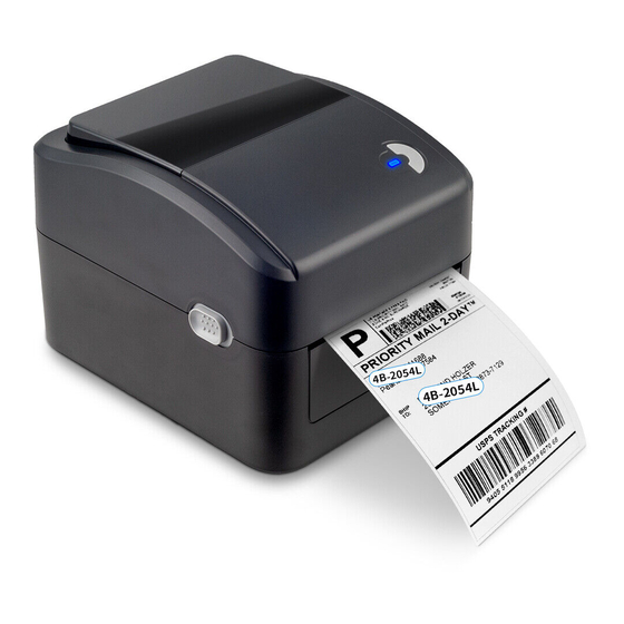
2. If the button battery RTC contained in the main board is not replaced correctly, the main board cannot be used normally. 3. Please dispose of the used batteries according to the manufacturer’s operation instructions. I. Product Thank you for purchasing our 4B-2054L series thermal barcode printer. This desktop... -
Page 5: Receiving
Meanwhile, its superior function and easy operation make it your best choice among the thermal barcode printers of the same level. The 4B-2054L series printer provides thermal printing. The printing speed is adjustable from 2.0, 3.0, 4.0, 5.0 to 6.0 inches per second. It applies to a variety of printing materials, including paper rolls, paper slices and fan-fold labels. -
Page 6: Unpacking And Checking Accessories
This printer is specially packaged to protect against possible damage in transit. However, since the printer may still be subjected to unexpected damage during transportation, you are kindly required to check the packaging and all units carefully when receiving the printer. In case of obvious damage, please contact the sales dealer directly and indicate the severity of the damage. -
Page 7: Printer Components
2.2 Printer components 2.2.1 Front view Transparent window Feed button Printer cover Power indicator Paper exit Cover hook Front panel 2.2.2 Rear view 1. Power switch 2. Power socket 3. USB interface 4. Ethernet interface 5. SD card slot 2 3 4 Note: The transmission interfaces of the printer in the picture will vary depending on the model of machine you purchase. -
Page 8: Installation
III. Installation 3.1 Install the printer 1. Place the printer on a smooth and steady surface and make sure the power is off. 2. Plug one end of the parallel port cable, serial port cable or USB cable into the slot on the back of the printer, and connect the other end of the cable to the appropriate slot of your computer. -
Page 9: Install The Label
3.2 Install the label 1. Install the label into the paper supply kit. (Fixing plate & Paper roll shaft ) Paper roll Fixing plate *1.5"纸卷轴榇套 纸卷 Fixing plate 固定片 打印面朝上 Print side up 纸卷轴 1" Paper roll shaft 2. Push the printer cover hook forward with both hands to open the printer cover. 3. -
Page 10: Install The Stripping Module - Optional
5. Close the printer cover. Note: To avoid poor printing quality, make sure the printer cover is closed tightly. 3.3 Install the peel-off module – optional 1. Push the cover hook forward with both hands to open the upper cover of the printer. 2. -
Page 11: Stripping Mode - Optional
3.4 Install the label with peel-off module 1. Pull the paper stripper apart. Peel-off roller front panel 2. Pass the label through the paper guide, and pull the label over the rubber roller. 3. Pass the label through the backing paper exit under the roller (as shown by the blue dotted line below). -
Page 12: Install The Cutter - Optional
5. Close the front panel. 6. Put on the upper cover of the printer. 3.5 Install the cutter – optional 1. Push the cover release button forward with both hands to open the upper cover of the printer. 2. Insert the cutter cable into the corresponding socket hole. 3. -
Page 13: General Button Functions
LED indicator color Description Blue (fixed) Power on, printer standby to print. Blue (blinking) The printer is downloading data or the printer is paused. Purple The printer is formatting the data. Red (fixed) Printer is in head opened or cutter error status. Printing error occurs, e.g. - Page 14 Please follow the steps below to calibrate the ribbon and gap/black mark sensor: 1. Turn off the printer. 2. Turn on the printer while holding down the feed button. 3. When the indicator blinks red after the first purple, release the feed button. Indicator color cycle mode: ...
- Page 15 Print head check sample Model & firmware version Machine serial number Print head mileage Check code Serial port setting Character set Country code Printing speed Printing density Paper size (width, height) Black mark or gap size (vertical gap, offset) Sensor strength Stored file information...
- Page 16 Debug mode After the self-test is printed, the printer system enters the debugging mode. In the debugging mode, all the volume labels will be printed as machine code. The ASCII strings on the left are the data received by the system. The data on the right are printed from the strings on the left, in hexadecimal values.
- Page 17 Note: Label paper of 4" wide is required to print all the debugging mode data. Restart the printer to leave the debugging mode and return to the normal printing mode, or press the FEED button to return to the standby state. 4.3.3 Printer initialization The printer initialization function is to clear the downloaded files in the memory (DRAM) and restore the print parameters to the factory default settings.
- Page 18 4.3.4 Skip the AUTO.BAS program The TSPL2 command language allows the user to load an auto-execute file (AUTO.BAS) into the flash memory. When the printer is turned on, it will be automatically executed according to the file loaded by the user. When you want to skip the AUTO.BAS after power-on, you can use this boot function to ignore this auto-execute file.
-
Page 19: Diagnostic Tool
V. Diagnostic Tool Diagnostic Tool is an easy-to-use window-type utility program that allows you to check the current status and settings of the printer, download graphic files, programs, font files, etc., and complete firmware updates according to the actual need. Moreover, it supports creation and download of dot-matrix fonts, transmission of commands or files and so on. -
Page 20: Printer Settings
5.2 Printer settings 1. Select the connection interface between your computer and the printer. The default communication interface of the Diagnostic Tool program is USB, so if the computer is connected through USB cable for transmission, no changes need to be made to the settings. -
Page 21: Set The Ethernet With The Diagnostic Tool (Optional)
5.4 Set the Ethernet with the Diagnostic Tool (optional) The Diagnostic Tool program is attached to the Utilities folder in the CD provided with the printer. The user can use the Diagnostic Tool to set up via USB, RS-232 or Ethernet interface through Ethernet. - Page 22 The factory default value set by such IP is “Automatically obtain the IP location”. If you need to change your IP location, please select “Designate the IP location” and enter the IP, subnet mask and gateway to be set, and then press the “Set IP” button to set, and the user can also change the name of the printer by pressing the “Set printer name”...
-
Page 23: Troubleshooting
VI. Troubleshooting 6.1 Common problems The table below shows the common problems the printer operators normally meet and the solutions to them; if you have tried the troubleshooting in the ways we suggest but the printer is still not working properly, please contact the customer service of the vendor for more assistance. - The power indicator is off. - Page 24 Problem Possible cause Solution * Reconnect the transmission line * If you are using a serial port cable, - Replace the serial port cable. The pin of the cable must be of 1 to 1 type - Make sure that the transmission rate of the printer is set to 9600, n,8,1 * If you are using an Ethernet cable, - Make sure that the Ethernet RJ-45 blue/purple...
- Page 25 Problem Possible cause Solution * The microSD memory * Use a microSD memory card with card is damaged supporting capacity - The microSD * The microSD memory * Re-insert the microSD memory card memory card is not card is not inserted correctly available * The microSD card is from unverified manufacturer...
- Page 26 Problem Possible cause Solution * The label sensor setting is * Recalibrate the label sensor incorrect * Set the correct volume label size and * The label size setting is volume label gap size incorrect * If the BarTender software is used, set * The vertical offset setting the vertical offset in the printer driver of the volume label style in...
-
Page 27: Simple Maintenance Procedures Of The Printer
VII. Simple maintenance procedures of the printer The simple maintenance procedures aim to ensure the printing quality and extend the life of the printer. Below are some of our recommended maintenance procedures. 1. Clean and maintain your printer by using the tools listed below: Cotton swab ... -
Page 28: Update History
This is a Class A product that may cause radio interference in a living environment. In such case, user may need to take practical measures accordingly Update history Date Content Editor August 12, 2019 First issue Hu Xiang... - Page 29 FCC Warning This device complies with part 15 of the FCC Rules. Operation is subject to the following two conditions: (1) This device may not cause harmful interference, and (2) this device must accept any interference received, including interference that may cause undesired operation. Any Changes or modifications not expressly approved by the party responsible for compliance could void the user's authority to operate the equipment.
Need help?
Do you have a question about the 4B-2054L Series and is the answer not in the manual?
Questions and answers
Здравствуйте, почему не печатаются цыфры в программе 4barcode