
Related Manuals for Xirgo Technologies XT4964

Summary of Contents for Xirgo Technologies XT4964
- Page 1 XT4964 User Guide Model: XT4964 FCC ID: GKM-XT4975A IC: 10281A-XT4975A Revision 1...
-
Page 2: Table Of Contents
Table of Contents Document Change History ..................3 1 Introduction ......................4 1.1 Feature Matrix ....................................4 2 Hardware Description ....................5 2.1 Hardware Specifications ................................6 2.2 Cable Harness Description ................................. 7 2.3 LED Description ....................................7 3 Device Mounting Options ..................8 3.1 Screw Mounting .................................... -
Page 3: Document Change History
Document Change History Revision Date Author Changes 10/24/2019 Johnny Chen Document Creation based off “XT4975A User Guide v2” 11/13/2019 Johnny Chen Removed Zigbee referenced due to removal of Zigbee HW support... -
Page 4: Introduction
1 Introduction The XT4964 is a solar energy harvesting cellular and GPS tracking device supporting long term, remote deployments without the need to replace the rechargeable battery. This user guide describes the physical hardware, associated parts, the different mounting options available, and a quick start-up procedure. -
Page 5: Hardware Description
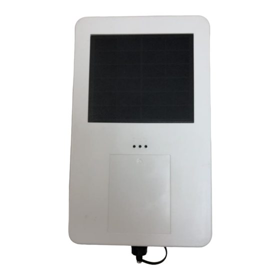
2 Hardware Description Below is a depiction of key interfaces of the XT4964: Device/FCC Label Wake-up Button Solar Panel LED Indicators Gore Vent 8-Pin Bayonet Connector The Associated Cable Harness that interfaces with the unit is shown below:... -
Page 6: Hardware Specifications
2.1 Hardware Specifications Cellular Technology Options ▪ 4G LTE Cat 4 4G LTE FDD bands: 1, 2, 3, 4, 5, 7, 8, 12, 13, 18, 19, 20, 26, 28 ▪ 4G LTE TDD bands: 38, 39, 40, 41 ▪ 3G UMT/HSDPA/HSUPA Band 1, 2 ,5, and 8 ▪... -
Page 7: Cable Harness Description
2.2 Cable Harness Description Pin # Wire Color Pin Name Functional Description Port Characteristic Blue VBATT Ignition Sense 8v to 24v, Internally pulled low Ground 2.4 to 24V, < 0.2 V Brown Note: Internally pulled high Yellow Black ADC2 8-24 V RS232 Receive Port 3V Logic Interface RS232 RX... -
Page 8: Device Mounting Options
3 Device Mounting Options 3.1 Screw Mounting The XT4964 has two flanges (two holes per) at each end of the housing for screw mounting the device to the mounting surface. 3.2 3M VHB Tape Mounting For a semi-permanent option, the device can be mounted with 3M VHB tape as shown below:... -
Page 9: Trailer Cradle Mounting
The cradle will need to be screw-mounted or VHB Tape mounted to the position desired. The XT4964 can be easily fastened into the cradle via a Phillips head screw. The angled edged of the cradle is designed to withstand the impact of snow scrapers that may come in contact to the cradle if mounted on the top of a typical trailer. -
Page 10: Device Mounting Guidelines
3.5 Device Mounting Guidelines The XT4964 Series devices leverage solar energy to replenish the charge of its battery. Please consider the device mounting guidelines to maximize device solar charging. Also, the XT4964 series uses cellular and GPS technologies whose signal reception quality is depending on mounting location and style. - Page 11 • The XT4964 must be mounted flush to a flat surface. Failing to mount the XT4964 to a flat surface can lead to excessive strain on the top plate which can compromise the device environmental seal and allow ingress of dust and water.
-
Page 12: Quick Start Guide
4 Quick Start Guide 4.1 Device Wakeup To start up the device, simply hold the black button located near the circular connector on the side panel of the device for 3 seconds. You should see the blue “C” LED light up and then fade out. The blue LED will blink when the device is successfully connected to the network. -
Page 13: Configuring The Device Via Sms
4.3 Configuring the Device via PC 1) A RS-232 to USB TTL converter cable is required to connect the XT4964 to a computer for local configuration. Connect the XT4964 Tx wire to the TTL converter cable Rx wire. Connect the XT4964 Rx wire to the TTL converter cable Tx wire. Connect the XT4964 ground wire to the ground wire of the TTL converter cable. -
Page 14: Download Over The Air (Dota) Firmware Update Guide
6) You can now configure the device by sending the XT commands listed in the protocol document of this device. a. Command +XT:1010 configures network settings b. Command +XT:3017 configures the sleep/wake mode for the device. i. The factory defaults for this device is to operate in the sleep timer mode and have a minute of wake time max. -
Page 15: Regulatory Statements
2) this device must accept any interference received, including interference that may cause undesired operation. Changes or modifications made to this equipment not expressly approved by Xirgo Technologies, LLC may void the FCC authorization to operate this equipment. NOTE: This equipment has been tested and found to comply with the limits for a Class B digital device, pursuant to Part 15 of the FCC Rules. - Page 16 Antenna Statement Under Industry Canada regulations, this radio transmitter may only operate using an antenna of a type and maximum (or lesser) gain approved for the transmitter by Industry Canada. To reduce potential radio interference to other users, the antenna type and its gain should be so chosen that the equivalent isotropically radiated power (e.i.r.p.) is not more than that necessary for successful communication.
Need help?
Do you have a question about the XT4964 and is the answer not in the manual?
Questions and answers