
Summary of Contents for STEEL AND PIPES SCORPION C600
- Page 1 operators C600 SLIDING GATE OPERATOR (100) USER’S MANUAL (MAGNETIC LIMIT SWITCH) www.steelandpipes.com...
-
Page 2: Table Of Contents
C600 SLIDING GATE OPERATOR OUTLINE 1. Important safety precautions………………………2 2. Main features ………………………………………2 3. Main technical parameters ………………………2 4. Necessary Tools ……………………………………3 5. Site Preparation ……………………………………3 6. Mechanical Installation ……………………………4 7. Electrical ……………………………………………7 8. Tuning and operation ……………………………11 9. Check ………………………………………………14 10. -
Page 3: Important Safety Precautions
C600 SLIDING GATE OPERATOR 1. Important safety precautions Carefully read and follow all safety precaution and warnings before attempting to install and use sliding gate operator, incorrect installation can lead to severe injury. l Installing the C600 gate operator requires installation of standard 110V electrical wiring. This work should only be performed by a trained technician. -
Page 4: Necessary Tools
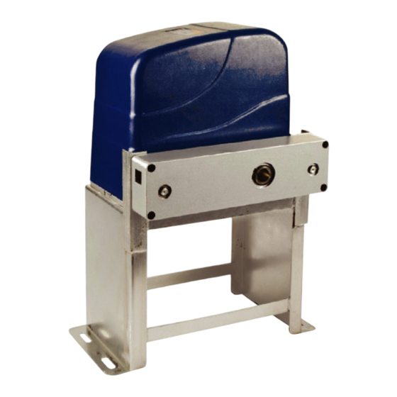
C600 SLIDING GATE OPERATOR Remote control mode Single Button Environmental temperature -20°C~+50°C Main unit dimension 263×240×153mm MCU logic voltage DC5V Net weight 21 Kg Emergency release key in case of power failure 4. Necessary Tools The following tools may be necessary to install the C600 Gate operator. You will need screwdrivers, an electric drill, wire cutters and a wire stripper, a socket set, and possibly access to a welder. - Page 5 C600 SLIDING GATE OPERATOR Fig.1 Installation and Adjustment The C600 Chain-driven Gate Operator operates by forcing a straight piece of chain through its chain box. This length of chain is extended between two chain brackets located at opposite ends of the gate. The entire configuration is shown in the diagram above. Concrete Pad The base unit of the gate operator requires a concrete pad in order to maintain proper stability.
- Page 6 C600 SLIDING GATE OPERATOR Gate operator Socket head cap screw Chain box Operator base Anchor bolt Anchor Conduit Cable Concrete pad Fig.2 Chain Box Make sure the ends of the guide chain are out of the chain holes on both sides of the chain box.
- Page 7 C600 SLIDING GATE OPERATOR Chain Brackets Use the appropriate bolts to attach the chain bracket to the frame of the gate. If the gate is of square frame style, use the square bolts shown. Gate Square frame Plain washer ( Φ 6) Square bolt Spring washer ( Φ...
-
Page 8: Electrical
C600 SLIDING GATE OPERATOR Magnets for Limit Switch Install the magnet and magnetic limit switch as shown in Fig.7. The magnet and limit switch are used to control the position of the gate. When the magnet is installed, release the gear clutch and push the sliding gate manually to pre-determine the position. - Page 9 C600 SLIDING GATE OPERATOR Control board scheme Fig.7...
- Page 10 C600 SLIDING GATE OPERATOR Wiring notes for control board 1. Power switch: ON/OFF 2. Fuse: 10A, Ø5x20 3. Antenna: ANT 4. Beeper: DC12V 5. DIP switch 6. Memory Card: 93C66 7. MCU: PIC 16C57C 8. External button switch (Three-button mode, Normally open contact): T (stop), G (close), K (open), COM (common) OPEN CLOSE...
- Page 11 C600 SLIDING GATE OPERATOR OPEN COM/U RELEASE CLOSED Motor wiring terminal MOTOR SWITCH REED SWITCHES +12V Control board Not used Wiring diagram 10. Output power supply: +12V (DC +12V), COM (CO), DET (Loop detector), I.R. (Infrared photocell N.C) Terminal X8, No.10 Terminal X8, No.10 AC24V Terminal...
-
Page 12: Tuning And Operation
C600 SLIDING GATE OPERATOR 8. Tuning and operation Remote control Button 2 Button 1 Button 3 Button 4 Fig.8 To add extra remote controls (Learning): Press the button ‘AN’ (See control board l scheme No.13) on the control board, then the ‘LED2’ will be on and turn off, the beeper will ring about 1 second, then press the remote control button which you want to use, the beeper will ring about 2 seconds and the ‘LED2’... - Page 13 C600 SLIDING GATE OPERATOR l Set auto-close function (This feature can be selected to make the gate stay open for some time before it automatically closes. The auto-close time can be adjusted to between 0 and 44 seconds.): please turn on the second and the third DIP switch (See Fig.7 terminal 5) to ON position.
- Page 14 C600 SLIDING GATE OPERATOR DIP switch 3 to OFF position immediately. Thus the width and auto-close function of pedestrian mode have been canceled. *Cancel width of pedestrian mode, keep auto-close function of pedestrian mode: Please turn on the second and the third DIP switch (See Fig.7 terminal 5) to ON position. Press button 4 to open the gate (see Verify open direction section).
-
Page 15: Check
C600 SLIDING GATE OPERATOR Activities Covered in this section l Remote control: With each press of the button, the gate will open, stop, close or stop cycle. (Single-button mode) l External button switch (not supply): two different modes (three-button or single- button) you can select according to your order. -
Page 16: Trouble Shooting
C600 SLIDING GATE OPERATOR 11. Trouble Shooting Trouble Possible causes Solutions The wire connector terminal block Check wire connector terminal block make becomes loose. sure it is plugged in terminal block 10 (X8). Check limit switch wire connector terminal The limit switch wire connector terminal block make sure it is plugged in terminal Motor only runs in one direction.
Need help?
Do you have a question about the SCORPION C600 and is the answer not in the manual?
Questions and answers