
Related Manuals for RTA 435NBX-NNA1


Summary of Contents for RTA 435NBX-NNA1
- Page 1 435NBX-NNA1 ASCII to PLC Gateway Product User Guide Revision: 8.06 Platform: NNA1 Real Time Automation, Inc. 1-800-249-1612...
- Page 2 Trademarks CompactLogix, ControlLogix, & PLC-5 are registered trademarks of Rockwell Automation, Inc. EtherNet/IP is a trademark of the ODVA. MicroLogix, RSLogix 500, and SLC are trademarks of Rockwell Automation, Inc. Microsoft, Windows, and Internet Explorer ® are registered trademarks of Microsoft Corporation. BACnet is a registered trademark of American Society of Heating, Refrigerating and Air-Conditioning Engineers (ASHRAE).
-
Page 3: Table Of Contents
Overview ............................... 5 Hardware ..............................6 Powering the Gateway ..........................6 Mounting with a DIN Rail ..........................7 Accessing the Gateways Configuration Pages ....................8 Error: Main Page Does Not Launch ......................9 Committing Changes to the Settings ......................10 Main Page .............................. - Page 4 Export Configuration ..........................29 Import Configuration ..........................29 Utilities ................................ 30 Revision Listing ............................30 Diagnostics Logging ..........................30 Security Configuration ..........................31 Security - Log In ............................31 Upgrade Firmware ..........................32 Reset Gateway ............................32 Intelligent Reset Button ..........................33 Save and Replace Configuration using SD Card ..................
-
Page 5: Overview
Overview The 435NBX gateway seamlessly connects an ASCII device to a ControlLogix, CompactLogix, FlexLogix, MicroLogix, PLC5E, SLC, or other legacy PLC featuring a NetENI module. Tools and documents available online: http://www.rtautomation.com/product/435-nbx-support/ If at any time you need further assistance do not hesitate to call Real Time Automation support. Support Hours are Monday-Friday 8am-5pm CST Toll free: 800-249-1612 Email: support@rtaautomation.com... -
Page 6: Hardware
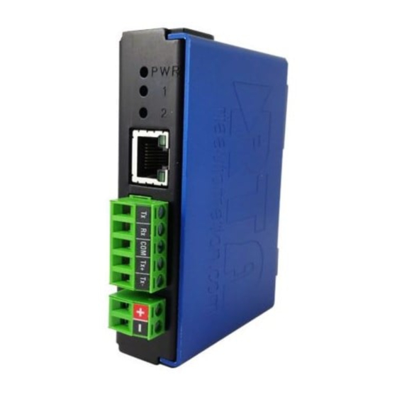
Hardware Powering the Gateway • An 8-24 VDC power source to the gateway, Red Wire = (+) Black Wire = (-). a. The unit draws 175mA @ 12V. Real Time Automation, Inc. 1-800-249-1612... -
Page 7: Mounting With A Din Rail
Mounting with a DIN Rail Installing Follow these steps to install your interface converter. 1) Mount your DIN Rail. 2) Hook the bottom mounting flange under the DIN Rail. 3) While pressing the 435NBX against the rail, press up to engage the spring loaded lower clip and rotate the unit parallel to the DIN Rail. -
Page 8: Accessing The Gateways Configuration Pages
Accessing the Gateways Configuration Pages Access the browser based configuration of the 435NBX. By default, DHCP is enabled. If the 435NBX fails to obtain an IP address over DHCP it will Auto IP with 169.254.X.Y. • Connect an 8-24 VDC power source to the gateway, Red Wire = (+) Black Wire = (-). •... -
Page 9: Error: Main Page Does Not Launch
Error: Main Page Does Not Launch If the Main Page does not launch, please verify the following: 1. Check that the PC is set for a valid IP Address a. Open a MS-DOS Command Prompt b. Type “ipconfig” and press enter c. -
Page 10: Committing Changes To The Settings
Committing Changes to the Settings • Any changes made to the IP address or DHCP settings will take effect immediately. • All other changes made to the settings of the gateway will not take effect until the gateway is restarted. Changes will not be stored if the gateway’s power is removed prior to a reboot. •... -
Page 11: Main Page
Main Page The main page is where important information about your gateway and its connections are displayed. Navigation (green box below): You can easily navigate between pages (Main, Configuration, Diagnostics, and Other pages) using the buttons on the left hand side. Device Status (orange box below): This quickly shows the high-level status of any ASCII Ports that are enabled in the Serial... -
Page 12: Device Configuration
Device Configuration 1) From the main page, click the Edit button which is located next to Device Configuration. 2) This allows you to edit the Device Description, IP Settings, IP Address, Subnet, Default Gateway and Ethernet Link settings. 3) To save all values, click the Save Parameters button. NOTE: Once Save Parameters is pressed, new IP Settings take effect immediately. -
Page 13: Plc Configuration
PLC Configuration 1) Click the PLC Configuration button under the CONFIGURATION section. 2) PLC Type: Select which PLC you are using. a. If using a Logix PLC, all processors are compatible. b. If using a PLC5E, then it must be: Series C, Revision N.1 or later; Series D, Revision E.1 or later;... - Page 14 a. This setting will affect the speed at which a message is delivered and the amount of traffic the gateway adds to the network. b. If set to 0, the gateway will communicate as fast as possible to the PLC and generate the most traffic.
-
Page 15: Nbx Serial Configuration
NBX Serial Configuration 1) From any page, click the Serial Configuration button under the CONFIGURATION section. 2) By default, Port 0 is configured for RS232. Port 0 can be configured for RS232 or RS485 communication. 3) All serial settings must match the serial device being connected. If any of these fields are incorrect, proper communication will not be possible. -
Page 16: Setting Up Ascii To Plc Communication
Setting up ASCII to PLC Communication Click the ASCII Configuration button under the CONFIGURATION section. Define PLC Tag / File 1) Data Type: Select the Data Type for the Tag / File Name that you defined in the PLC. a. If PLC Type configured is I/O Scanner, then this field is not used. 2) Enter the Tag / File name you want the gateway to move the ASCII message to. -
Page 17: Define Ascii Message Termination
Define ASCII Message Termination 1) To define an ASCII message, you must select one or more of the following end cases: Character Count, Timer, or Delimiters. a. Character Count: Enter the max number of characters that the device could output. Example: If your device sends a four digit temperature, set the length to 4. -
Page 18: Message Queue
Message Queue 1) Queue Size: Enter the number of complete messages you want the gateway to hold before discarding. 2) Queue Full Behavior: If the Queue is full, the gateway will discard messages one of the following ways: a. Discard New Data: Gateway will discard any new messages. b. -
Page 19: Setting Up Plc To Ascii Communication
Setting up PLC to ASCII Communication Click the ASCII Configuration button under the CONFIGURATION section. Define PLC Tag / File 1) Data Type: Select the Data Type for the Tag / File Name that you defined in the PLC. a. If PLC Type configured is I/O Scanner, then this field is not used. 2) Enter the Tag / File name that you want the gateway to monitor for messages. -
Page 20: Add Delimiters To Ascii Message
iii. SINT: Not Used Add Delimiters to ASCII Message 1) Delimiters: Configure the characters to add to the message. a. Start: Use this feature to add a common starting delimiter(s) to messages being sent to the ASCII device. i. The value of this first dropdown will either gray out or allow a delimiter to be selected from the next dropdown. -
Page 21: Diagnostics And Troubleshooting
Diagnostics and Troubleshooting From any page, click the Diagnostics button under the DIAGNOSTICS section. PLC Status PLC Status: Shows same information that is on the main page diagnostics. See section Diagnostics-Main Page for further explanations. Connection Attempts: This value increments every time the 435NBX loses connection to the PLC and attempts to reconnect. -
Page 22: Diagnostics And Troubleshooting - Ascii To Plc
Diagnostics and Troubleshooting – ASCII to PLC This page will automatically refresh to show the latest data. Last message sent to PLC (chars): This buffer shows the last message that was successfully sent to the PLC. Next message stored in ASCII queue (chars – messages queued): This buffer shows the next ASCII message waiting to be sent. -
Page 23: Diagnostic Counters
• This message will not work if buffer is already full. Message will be discarded. Diagnostic Counters ASCII Event: Delimiter: Increments if a successful ASCII message was received with delimiters being read. Length: Increments if a successful ASCII message was received containing the max character count. -
Page 24: Diagnostics And Troubleshooting - Plc To Ascii
Diagnostics and Troubleshooting – PLC to ASCII This page will automatically refresh to show the latest data. Last message sent to ASCII (chars): This buffer shows the last message that was sent to the ASCII device. Data portion should be filled in first and then the Length field. -
Page 25: Diagnostic Counters
Diagnostic Counters Read ASCII Message from PLC: Increments with every read request for the length field from the gateway. Increments Error: when there is an error with the Tag/File Name in the PLC. Last Error: This will report the most recent error found. Note: Errors that show up here are reported from either the 435NBX or the PLC. -
Page 26: Diagnostics And Troubleshooting - Leds
Diagnostics and Troubleshooting – LEDs When both LEDs blink Red alternating like railroad crossing lights, the gateway’s configuration has been changed and is expecting a reboot. If the PLC Type of the gateway is configured for I/O Scanner, LED 2 has special meaning. See Appendix B for further information. -
Page 27: Diagnostics - Main Page
Diagnostics – Main Page For a snapshot diagnostic view of the gateway, go to the Main Page. This page will automatically refresh. PLC Status This shows the Status of the PLC Connection. Possible values are: 1) No PLC Configured – Displays when either a PLC Type is not selected and/or the IP address is set to 0.0.0.0. -
Page 28: Device Status
Device Status There are 3 columns that make up this status. The status reflected here show the current status for configured parameters. This means that any pending changes made to that parameter since it was last powered up will not display. Example: If since the last power up, the serial port has since been disabled, you will need to restart the gateway in order to see that port row disappear from the main page. -
Page 29: Save/Load The Configuration
Save/Load the Configuration Click the Export/Import Config button under the OTHER section. Export Configuration 1) Click the Save Configuration to PC button. 2) A prompt will then ask the type of file to save as. Any type will suffice. 3) This will save all of the configuration except for the Gateway’s IP Network Settings, since this must be unique. -
Page 30: Utilities
Technical Support Specialist. Diagnostics Logging Most users will not need to do anything with this feature. If there are problems with the gateway, a RTA Technical Support Specialist will direct you in how to use this feature. Real Time Automation, Inc. -
Page 31: Security Configuration
Security Configuration Click on the Security button to configure security for a single username and password. 1) Log Out Timer: The system will automatically log inactive users off after this period of time. 2) Username: Enter a username, max of 30 characters, case sensitive. 3) Password: Enter a password for the username, max of 30 characters, case sensitive. -
Page 32: Upgrade Firmware
Upgrade Firmware Click the Upgrade Firmware button if you need to upgrade firmware for the gateway. From here, click Choose File and select the XXXXX_APP.s19 file. Once the file name appears next to Application File, click the Upgrade Firmware button. The firmware will load and will automatically reboot the gateway after 30 seconds and redirect the webpage to the Main Page when finished. -
Page 33: Intelligent Reset Button
Intelligent Reset Button If the IP Address of the gateway is forgotten or unknown, there is an easy way to recover the IP Address using a reset button on the hardware. 1) On the side of the gateway with the SD card slot, there is a small pinhole. Using a small paperclip, press the button through this pinhole and hold the button for at least 5 seconds. -
Page 34: Save And Replace Configuration Using Sd Card
Set→ button is pressed. This is intended as an extra precaution to ensure that the IP Address should be modified from what is currently stored in the SD Card. 1. Enter a UserName of RTA. 2. Enter a Password of RTA. -
Page 35: Appendix A: Error Definitions
Appendix A: Error Definitions Error Status Name Description 0x00 Success Service was successful 0x01 Controller Slot Doesn’t Exist Connection related service failed along the connection path 0x02 Resource unavailable Resources needed for the object requested service were unavailable 0x03 Invalid parameter value See Error 0x20 0x04 Incorrect Tag Data Type... - Page 36 0x0F Privilege violation A permission/privilege check failed 0x10 Device state conflict The device’s current mode/state prohibits the execution of the requested service 0x11 Reply data too large The data to be transmitted in the response buffer is larger than the allocated response buffer 0x12 Fragmentation of a primitive value The service specified an operation that is going to...
- Page 37 with status information for those attributes that were invalid 0x1E Embedded server error An embedded service resulted in an error: This can mean the Controller Slot, IP Address or Tag Name does not match. The Tag is not defined in the Controller Scope within the PLC, or the Tag does not have Read/Write privileges.
- Page 38 0x27 Unexpected attribute An attempt was made to set an attribute that is not able to be set at this time 0x28 Invalid member ID The Member ID specified in the request does not exist in the specified Class/Instance/Attribute 0x29 Member not settable A request to modify a non-modifiable member was received...
-
Page 39: Appendix B: I/O Messaging - Configuration (Rev 7.03 Or Later)
Appendix B: I/O Messaging - Configuration (Rev 7.03 or Later) In order to enable I/O Messaging, under the PLC Type dropdown select I/O Scanner on the PLC Configuration page. Once you enable I/O Messaging, the Tag Name and Data Type in the ASCII to PLC and PLC to ASCII direction will not be used. -
Page 40: Input / Output Assembly Handshaking Breakdown
Input / Output Assembly Handshaking Breakdown ASCII to PLC The PLC monitors the Input Sequence Number for a non-zero value that doesn’t match the Input Handshake. This indicates new data is ready for processing. Upon receiving new data, the PLC reads the length of the data and processes it (up to 200 bytes). The PLC then echoes the Input Sequence Number into the Input Handshake. -
Page 41: Appendix C: Create User Defined Tag In Rslogix 5000
Appendix C: Create User Defined Tag in RSLogix 5000 1) Within RSLogix 5000, click on Data Types and select Strings. 2) Right click on String and select New String Type. Give the new data type a name. 3) Select the max number of characters to be transferred. 4) When creating the tag name in the PLC, select the name of the new user defined data type you just created. -
Page 42: Appendix D: How To Access Program Scope Tags In Rslogix 5000
Controller Scope tags, these tag names can be entered into the gateway without any additional syntax. If you are using a tag that is defined within Program Scope, then the tag name inside of the RTA gateway needs additional syntax for it to successfully communicate.
Need help?
Do you have a question about the 435NBX-NNA1 and is the answer not in the manual?
Questions and answers