
Subscribe to Our Youtube Channel
Related Manuals for Fast CSP10

Summary of Contents for Fast CSP10
- Page 1 CSP10 … 13 Charge Sensitive Preamplifier User Manual Copyright FAST ComTec GmbH Grünwalder Weg 28a, D-82041 Oberhaching Germany Version 1.0, September 17, 2009...
- Page 2 During the warranty period, repairs or replacement will be made at FAST ComTec’s option on a return to factory basis. The transportation cost, including insurance to FAST ComTec is the responsibility of the Costumer except for defects discovered within 30 days after receipt of equipment where shipping expense will be paid by FAST ComTec.
-
Page 3: Table Of Contents
Initial Checkout......................5-1 5.5. Common Operating Problems..................5-1 6. Theory of Operation ........................ 6-1 6.1. Functional Description....................6-1 6.2. Detailed Circuit Description ..................6-1 7. Appendix ..........................7-1 7.1. Detailed Schematic of the CSP10…13 ..............7-1 7.2. Personal Notes......................7-2 ComTec GmbH... - Page 4 WARNINGS WARNINGS The input of the CSP1X is very sensitive. Never connect the detector when the high voltage is applied. Increase or decrease the high voltage only at a very slow rate. Observe the output of the CSP1X during bias voltage change with an oscilloscope. Do not allow the output to saturate during change of high voltage.
-
Page 5: Introduction
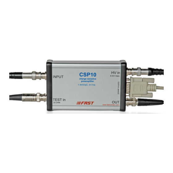
As with all FAST ComTec’s preamplifier modules, the CSP10...13 is housed in a small shielded metal case with a D-sub 9 connector for power supply. The FAST ComTec Model CSP10...13 Charge Sensitive Preamplifier is designed for optimum performance with Silicon Surface Barrier (SSB) detectors. - Page 6 Introduction ComTec GmbH...
-
Page 7: Specifications
Specifications Specifications 2.1. Inputs @ 20ºC, ±12V, unloaded output Preamplification channels: 1 up to ± 4000 volts (SHV) Test input 50 ohms terminated for tail pulser 2.2. Outputs Decay time constant: 140 µs (150 µs, 50 µs, 50 µs resp.) Unsaturated output swing: -3 to +3 volts Output offset: +0.2 to -0.2 volts Output impedance: 50 ohms... -
Page 8: Physicals
Specifications Power supply current: < 10 mA Power dissipation: < 240 mW 2.6. Physicals Net weight: 250 gr. Size without connectors: 126 mm x 80 mm x 30 mm Size with connectors: 165 mm x 80 mm x 30 mm •... -
Page 9: Controls And Connectors
3.1. General This section describes the functions of the controls and connectors located on the front and rear panels of the Model CSP10...13. It is recommended that this section be read bevor proceeding with the operation of the preamplifier. 3.2. -
Page 10: Installation
Any capacitance added to the input of the preamplifier will increase the noise contribution and degrade the rise time performance of the Model CSP10…13. The capacitance should be minimized by using the shortest possible interconnecting cable between the detector and the preamplifier. -
Page 11: Operating Instructions
5.1. General The purpose of this section is to familiarize the user with the Model CSP10...13 Preamplifier and to check that the unit is operating correctly. Since it is difficult to determine the exact system configuration in which the unit will be used, explicit operating instructions cannot be given. - Page 12 Operating Instructions All of the many possible contributors to less than optimum performance cannot be listed here. The purpose of this section is to note the usual causes of loss of resolution, and to suggest curative steps. Do not expect to diagnose all problems with the detector, a preamplifier, a main amplifier, and a multichannel analyzer.
-
Page 13: Theory Of Operation
Figure 2 shows a simplified equivalent circuit diagram of the hybrid amplifier module used in the CSP10...13, which is a two stage amplifier. The first stage is high gain, and the second stage is low gain with an emphasis on supplying sufficient output current to drive a terminated coaxial cable. - Page 14 Theory of Operation- Detailed Circuit Description high voltage path with filter circuit and • power supply circuitry • ComTec GmbH...
-
Page 15: Appendix
Appendix- Detailed Schematic of the CSP10(…13) Appendix 7.1. Detailed Schematic of the CSP10(…13) ComTec GmbH... -
Page 16: Personal Notes
Appendix- Personal Notes 7.2. Personal Notes ComTec GmbH...
Need help?
Do you have a question about the CSP10 and is the answer not in the manual?
Questions and answers