
Related Manuals for Portwell WEBS-35C6


Summary of Contents for Portwell WEBS-35C6
- Page 1 WEBS-35C6 Fan-less Embedded System AS5-3522 User's Manual Version 1.0 Copyright © Portwell, Inc., 2018. All rights reserved. All other brand names are registered trademarks of their respective owners.
-
Page 2: Table Of Contents
Table of Contents How to Use This Manual Chapter 1 System Overview ....................... 1-1 1.1 Introduction ....................... 1-1 1.2 Check List ......................1-2 1.3 Product Specification ..................1-2 1.4 Mechanical Dimension ..................1-3 Chapter 2 System Installation ....................2-1 2.1 CPU and Memory module Installation............2-1 2.2 HDD Installation .................... -
Page 3: How To Use This Manual
How to Use This Manual The manual describes how to configure your WEBS-35C6 system to meet various operating requirements. It is divided into four chapters, with each chapter addressing a basic concept and operation of Fan-less Embedded System. Chapter 1: System Overview. Present what you have in the box and give you an overview of the product specifications and basic system architecture for this fan-less embedded system. -
Page 4: Chapter 1 System Overview
The rugged, fan-less design makes the WEBS-35C6 durable in harsh environment applications, such as factory automation and industrial automation. Portwell’s WEBS-35C6 has already passed a vibration test of 5Grms/ 5~500Hz and a shock test of 50G, assuring its solidity and reliability. -
Page 5: Check List
System Overview Check List The WEBS-35C6 package should cover the following basic items: One WEBS-35C6 Fan-less Embedded System ✓ One Wall Mount Kit ✓ ✓ Other Accessories If any of these items is damaged or missing, please contact your vendor and keep all packing materials for future replacement and maintenance. -
Page 6: Mechanical Dimension
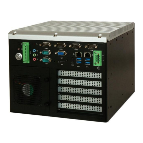
95% @ 40℃, non-condensing Operating Vibration 5Grms/5~500Hz, IEC 60068-2-6 Operating Shock 50G, 11 msec, IEC 60068-2-27 Mechanical Dimension (WxDxH) 253 x 255 x 210 mm Weight 9 kg Mounting Wall Mount 1.4 Mechanical Dimension Front view of the WEBS-35C6 system WEB-35C3 User’s Manual... - Page 7 System Overview Rear view of the WEBS-35C6 system WEB-35C3 User’s Manual...
- Page 8 System Overview Top view of the WEBS-35C6 system WEB-35C3 User’s Manual...
-
Page 9: Chapter 2 System Installation
System Installation Chapter 2 System Installation This chapter provides you with instructions to set up your system. Definitions and locations of all the interfaces are described so that you can easily configure your system. For more detailed PIN assignment and jumper setting, please refer to user’s manual of WADE-8017. - Page 10 System Installation Step 5. Install CPU. Please locate Step 6. Install CPU successfully notches on both side and pin one of CPU first Step 7. Remove film of thermal pad on Step 8. Remove film of thermal pad on heat spreader heat spreader Step 9.
- Page 11 System Installation Step11. Make sure CPU and Memory Step12. Fixed the screws of top module are installation successfully heatsink (there are 4 screws) WEB-35C3 User’s Manual...
-
Page 12: Hdd Installation
System Installation 2.2 HDD Installation Unique design of the HDD tray allows easy installation and maintenance of 2.5” HDD/SSD. RAID function is supported with dual HDD/SSD design. (The height must be less than 10mm) Step 1. Loosen the screws of the Step 2. -
Page 13: Pcie/Pci Add-On Card Installation
System Installation 2.3 PCIe/PCI Add-on Card Installation Equipped with an innovative PCIe expansion module, user can easily install and replace their own expansion cards. There are three types of riser cards: 2x PCIe x4 slots (with PCIe x1 signal) ⚫ 1x PCIe x 8 slot (with PCIe x8 signal) &... - Page 14 System Installation Install PCIe/PCI add-on card on 2x PCIe x4 riser card or 1x PCI and 1x PCIe x4 riser card. Step 1. Loosen the screws of the Step 2. Insert PCIe add-on card expansion cover WEB-35C3 User’s Manual...
- Page 15 System Installation Add-on card dimension limitation: Max dimension of add-on card in WEBS-35C6 is 176.65 x 113.9 mm. WEB-35C3 User’s Manual...
-
Page 16: I/O Interfaces
System Installation 2.4 I/O Interfaces 2.4.1 Rear View DC in 12-36V via 3-pin terminal block connector: Provide power connection of the system to the main power source via DC power cable or AC/DC power adapter. ANT1 & ANT2 hole: Antenna holes for WiFi or 3G/GPS module GPIO: WEB-35C3 User’s Manual... - Page 17 System Installation Signal Signal GPIO0 GPIO4 GPIO1 GPIO5 GPIO2 GPIO6 GPIO3 GPIO7 VCC5 Audio: Connectors for Mic-In, Line-In and Line-Out LAN: Two Gigabit Ethernet (10/100/1000 Mbits/sec) LAN ports by using Intel ® I219LM & Intel I211AT GbE Ethernet Controller ® USB3.0 &...
-
Page 18: Getting Started
System Installation RXD#/DT+ TXD#/422R+ DTR#/422R- DSR# RTS# CTS# 2.5 Getting Started It is easy to get the system started. Step 1. Make sure the power supply Step 2. Press the power button to turn (12~36V) is connected properly on the system WEB-35C3 User’s Manual 2-10... -
Page 19: Chapter 3 Bios Setup Information
System Installation Chapter 3 BIOS Setup Information WEBS-3585 system adopts WADE-8017 mother board. WADE-8017 is equipped with the AMI BIOS stored in Flash ROM. These BIOS has a built-in Setup program that allows users to modify the basic system configuration easily. This type of information is stored in CMOS RAM so that it is retained during power-off periods. -
Page 20: Main
System Installation 3.2 Main Once you enter WADE-8017 AMI BIOS CMOS Setup Utility, a Main Menu is presented. The Main Menu allows user to select from eleven setup functions and two exit choices. Use arrow keys to switch among items and press <Enter> key to accept or bring up the sub-menu. -
Page 21: Configuration
System Installation 3.3 Configuration Use this menu to set up the items of special enhanced features CPU Configuration CPU Configuration Parameters Feature Description Options Active Processor Number of cores to enable in each processor package. ★All, 1, 2, 3 Cores Intel When enabled, a VMM can utilize the additional ★Enabled,... - Page 22 System Installation Configurable TDP Mode Lock sets the Lock bits on TURBO_ACTIVATION_RATIO ★Disabled, Configurable CONFIG_TDP_CONTROL. TDP Lock Note: When CTDP Lock is enabled Custom COnfigTDP Enabled Count will be forced to 1 and Custom ConfigTDP Boot Index will be forced to 0. Enables CTDP control via runtime ACPI BIOS methods.
- Page 23 System Installation Chipset Configuration Configuration Chipset feature Feature Description Options Disabled, VT-d VT-d capability ★Enabled Above Enable/Disable above 4GB Memory Mapped IO BIOS Enabled, MMIO BIOS assignment. This is disabled automatically when ★Disabled assignment Aperture Size is set to 2048MB. Control Detect of the HD-Audio device.
- Page 24 System Installation AMT Configuration Configure Active Management Technology Parameters Feature Description Options Enable/Disable Intel ® Active Management Technology BIOS Extension. ★Disabled, Note: iAMT H/W is always enabled. Intel AMT (Enabled) This option just controls the BIOS extension Enabled execution. If enabled, this requires additional firmware in the SPI device ★Disabled, OEMFlag Bit 15: Un-Configure ME without...
- Page 25 System Installation Feature Description Options ★Enabled, Enable or disable onboard NIC Controller Disabled Enable or disable integrated LAN to wake the system. ★Enabled, Wake on LAN (The Wake On LAN cannot be disabled if ME is on at Sx Disabled state.) Launch Legacy PXE Rom.
- Page 26 System Installation Graphics Configuration Configuration Graphics Settings Feature Description Options ★Auto, Select which of IGFX/PEG/PCI Graphics device should IGFX, Primary Display be Primary Display Or select SG for Switchable Gfx. PEG, PCIE,SG ★Auto, Select Auto/PEG11/ PEG12 Graphics device should be PEG11, Primary PEG Primary PEG.
- Page 27 System Installation M,1024M,1536M,2 M,4M,8M,12M,16 M,20M,24M,28M,3 2M,/F7,36M,40M,4 4M,48M,52M,56M DVMT Total Gfx Select DVMT5.0 Total Graphic Memory size used by the 128M, ★256,MAX Internal Graphics Device Select the Video Device which will be activated during POST. This has no effect if external graphics present. ★VBIOS Default, Primary IGFX...
- Page 28 System Installation PCI/PCIE Configuration PCI, PCI-X and PCI Express Settings. Feature Description Options Disabled Express Enable or disable PCI Express Clock Gating for each ★Enabled Clock Gating root port. Disabled DMI Link ASPM Enable/Disable the control of Active State Power ★Enabled Control Management on SA side of the DMI Link.
- Page 29 System Installation PCI Express Root Port4, 6-8, 11, 13-18 PCI Express Root Port 4, 6-8, 11, 13-18 Feature Description Options Express Disabled, ★Enabled Root Port 4, 6-8, Control the PCI Express Root Port. 11, 13-18 Set the ASPM Level: Force L0s – Force all links to L0s ★Disabled, L0s, L1, ASPM Support State AUTO-BIOS auto configure, DISABLE –...
- Page 30 System Installation SATA Configuration SATA Device Options Settings Feature Description Options ★Enabled, SATA Enable or disable SATA Device. Controller(s) Disabled SATA Mode ★AHCI, RAID Determines how SATA controller(s) operate. Selection Disabled, ★Enable Port 0-5 Enable or Disable SATA Port ★Disabled, Hot Plug Designates this port as Hot Pluggable Enabled...
- Page 31 System Installation USB Configuration USB Configuration Parameters. Feature Description Options Enables Legacy USB support. AUTO option disables ★Enabled, Legacy legacy support if no USB Support Devices are connected. DISBLE option will keep USB Disabled, Auto devices available only for EFI applications. ★Enable, XHCI Legacy...
- Page 32 System Installation PCH USB Configuration PCH USB Configurtion Feature Description Options Enabled, Precondition work on USB host controller and root USB Precondition ★Disabled ports for faster Enumeration. ★Disabled, xDCI Support Enable/Disable xDCI (USB OTG Device). Enabled USB Port Disable Selectively Enable/Disable the corresponding USB ★Disabled, Select Override port from reporting a Device Connection to the...
- Page 33 System Installation Power Control Configuration System Power Control Configuration Parameters Feature Description Options Enables or Disables System ability to Hibernate Disabled, Enable Hibernation (OS/S4 Sleep State). This option may be not ★Enabled effective with some OS. Suspend Disabled, Select the highest ACPI sleep state the system will ★S3 ACPI Sleep State enter when the SUSPEND button is pressed.
- Page 34 System Installation TPM Configuration Trusted Computing settings Feature Description Options Enables or Disables BIOS support for security ★Disabled, Security Device Support device. O.S. will not show Security Device. TCG EFI (Enabled) Enabled protocol and INT1A Interface will not be available. TPM 1.2 will restrict support to TPM 1.2 devices, TPM 2.0 will restrict support to TPM 2.0 devices, Auto TPM 1.2, TPM...
- Page 35 System Installation Super IO Configuration System Super IO Chip Parameters. Feature Description Options Watch Dog Timer ★Disabled, Enabled Enable/Disable Watch Dog Timer (Enabled) ★Second, Minute Timer Unit Select Timer count unit of WDT ★20 Timer value Set WDT Timer value WEB-35C3 User’s Manual 3-27...
- Page 36 System Installation Serial Port 1 Configuration Set Parameters of Serial Port 1 (COMA) Feature Description Options Disabled, ★Enabled Serial Port Enable or Disable Serial Port (COM) ★Auto, IO=3F8h; IRQ=4; IO=3F8h; IRQ=3,4,5,6,7,9,10,11,12 IO=2F8h; Change Settings Select an optimal settings for Super IO Device IRQ=3,4,5,6,7,9,10,11,12 IO=3E8h;...
- Page 37 System Installation Serial Port 2 Configuration Set Parameters of Serial Port 2 (COMB) Feature Description Options Enable or Disable Serial Disabled, ★Enabled Serial Port Port (COM) ★RS-232, Serial Port RS-232/422/485 Control Option RS-232/422/485 Control RS-485 HALF DUPLEX, Option RS-485/422 FULL DUPLEX ★Auto, IO=2F8h;...
- Page 38 System Installation Feature Description Options Disabled, ★Enabled Serial Port Enable or Disable Serial Port (COM) Enabled is RS485 Mode and Disable is ★Disabled, Enabled Serial Port RS-485 Mode RS232 Mode Auto, ★IO=240h; IRQ=11, IO=240h; IRQ=3,4,5,6,7,10,11,12 Select an optimal setting for Super IO IO=248h;...
- Page 39 System Installation Serial Port 4 Configuration Set Parameters of Serial Port 4 (COMD) Feature Description Options Disabled, ★Enabled Serial Port Enable or Disable Serial Port (COM) Enable is RS485 Mode and Disable is ★Disabled, Enabled Serial Port RS485 Mode RS232 Mode Auto, ★IO=248h;...
- Page 40 System Installation Serial Port 5 Configuration Set Parameters of Serial Port 5 (COME) Feature Description Options Disabled, ★Enabled Serial Port Enable or Disable Serial Port (COM) Enable is RS485 Mode and Disable is ★Disabled, Enabled Serial Port RS485 Mode RS232 Mode Auto, ★IO=250h;...
- Page 41 System Installation Serial Port 6 Configuration Set Parameters of Serial Port 6 (COMF) Feature Description Options Enable or Disable Serial Port Disabled, ★Enabled Serial Port (COM) ★RS-232, RS-485 HALF Serial Port 6 RS-232/422/485 RS-232/422/485 Control Option DUPLEX, RS-485/422 Control Option FULL DUPLEX Enable is RS485 Mode and ★Disabled, Enabled...
- Page 42 System Installation H/W Monitor Configuration Monitor hardware status Feature Description Options ★Disabled, Smart CPU Fan Function Enable or Disable Smart CPU Fan (Enabled) Enabled CPU Start Target Temp CPU Start Fan Target Temperature. CPU Full Target Temp CPU Full Fan Target Temperature. ★Disabled, Smart System Fan Function Enable or Disable Smart System Fan Enabled...
- Page 43 System Installation Serial Port Console Redirection Serial Port Console Redirection Feature Description Options ★Disabled, Console Redirection (COM 0-5) Console Redirection Enable or Disable. (Enabled) Enabled WEB-35C3 User’s Manual 3-35...
- Page 44 System Installation COM 0-5 Serial Port Console Redirection Serial Port Console Redirection Feature Description Options Emulation: ANSI: Extended ASCII char set. VT100: ASCII char set. VT100+: Extends VT100, VT100+, Terminal Type VT100 to support color, function VT-UTF8, ★ANSI keys, etc. VT-UTF8: Uses UTF8 encoding to map Unicode chars onto 1 or more bytes.
- Page 45 System Installation Communication with slow devices may require more than 1 stop bit. Flow control can prevent data loss from buffer overflow. When sending data, if the receiving buffers are full, a ‘stop’ signal ★None, can be sent to stop the data Hardware Flow Control flow.
-
Page 46: Security
System Installation 3.4 Security This section lets you set security passwords to control access to the system at boot t ime a n d/ o r whe n en t erin g t h e B I OS se tu p pro g ra m . Feature Description Options... -
Page 47: Boot
System Installation Boot Use this menu to specify the priority of boot devices. Feature Description Options ★On, Off Bootup NumLock State Select the keyboard NumLock state UPON REQUEST – GA20 can be disabled, ★Upon Request, using BIOS services. ALWAYS – do not allow GateA20 Active disabling GA20;... -
Page 48: Save & Exit
System Installation 3.6 Save & Exit Feature Description Options Equal to F10, save all changes of all Save Changes and Reset menus, then exit setup configure driver. Finally resets the system automatically. Equal to ESC, never save changes, Discard Changes and Reset then exit setup configure driver. -
Page 49: Chapter 4 Important Instructions
4.2 Exclusion of Accident Liability Obligation Portwell, Inc. shall be exempt from the statutory accident liability obligation if users fail to abide by the safety instructions. 4.3 Liability Limitations / Exemption from the Warranty Obligation In the event of damage to the system unit caused by failure to abide by the hints in this manual and on the unit (especially the safety instructions), Portwell, Inc. -
Page 50: Chapter 5 Frequent Asked Questions
Default Clean CMOS Question: How to update the BIOS file? Answer: 1. Please visit web site of Portwell download center as below hyperlink http://www.portwell.com.tw/support/download_center.php Registering an account in advance is a must. (The E-Mail box should be an existing Company email address that you check regularly.) http://www.portwell.com.tw/member/newmember.php... - Page 51 Frequent Asker Questions SHELL MODE: SHELL MODE 6. When you see the “FPT Operation Passed” message, which means the BIOS update processes finished. Please cut the AC power off and wait for 10 seconds before powering on. DOS MODE: update.bat SHELL MODE: SHELL MODE 7.
- Page 52 Frequent Asker Questions WEB-35C3 User’s Manual...
Need help?
Do you have a question about the WEBS-35C6 and is the answer not in the manual?
Questions and answers