
Related Manuals for Panasonic AK-HC910


Summary of Contents for Panasonic AK-HC910
- Page 1 1080I Multi-purpose Digital Camera AK-HC910P Before attempting to connect, operate or adjust this product, please read these instructions completely.
-
Page 2: For Your Safety
For Your Safety CAUTION RISK OF ELECTRIC SHOCK DO NOT OPEN CAUTION: TO REDUCE THE RISK OF ELECTRIC SHOCK, DO NOT REMOVE COVER (OR BACK). NO USER SERVICEABLE PARTS INSIDE. REFER TO SERVICING TO QUALIFIED SERVICE PERSONNEL. lightning arrowhead symbol, within an equilateral triangle, is intended to alert the user to the presence of uninsulated “dangerous... -
Page 3: Table Of Contents
CONTENTS For Your Safety...2 Preface ...4 Features...4 Precautions...5 Major Operating Controls and Their Functions ...6, 7 How to Install ...8 How to set the lens ...8 How to install on the camera housing, pan/tilt head, tripod, etc..8 How to Set Up the System (Connection) ...9 Multi-purpose Digital Camera Control System Configuration 1...10... -
Page 4: Preface
Thank you very much for purchasing the multi-purpose digital camera. Preface This camera employs new 2/3q 2.2 million-pixel FIT CCD [1920(H)k1080(V)], realizing a compact light-weight system including the optical system. Also, the newly developed CCD having an FIT configuration suited for higher picture quality and the development of low-noise, high-speed amplifiers have enabled the realization of high sensitivity, high S/N ratio, and wide dynamic range. -
Page 5: Precautions
Precautions DON’TS • Do not attempt to disassemble the camera or other units. In order to prevent electric shock, do not remove screws or covers. There are no user-serviceable parts inside. • Do not abuse the camera. Avoid striking, shaking, etc. The camera contains sensitive components which could be damaged by improper handling or storage. -
Page 6: Major Operating Controls And Their Functions
Major Operating Controls and Their Functions _ Front Panel 1 Lens Mount 2/3q standard bayonet type (B4 mount) lens is installed. 2 Lens Fixing Ring Knob Lens is fixed by turning the knob counterclockwise. 3 Cable Clamp Used to clamp the lens cable. 4 Lens Connector [LENS] Used to connect the camera cables of the lens. -
Page 7: Their Functions
Major Operating Controls and Their Functions 6 Camera mounting hole (1/4-20UNC) 7 Camera mounting hole (3/8-16UNC) The screw holes can be used to secure the camera for installing it on camera housing, and when using a pan/tilt head or a tripod. _ Side Panel 8 Breaker [BREAKER] If the breaker is operated due to over-current or the like, check the cause and eliminate... -
Page 8: How To Install
How to Install _ How to set the lens • Standard 2/3q bayonet type (B4 mount) lens of any makers can be used*. 1 Turn the lens fixing ring knob counterclockwise to remove the lens mount cap. 2 Set the lens in place, and turn the lens fixing ring knob clockwise to precisely fix the lens. -
Page 9: How To Set Up The System (Connection)
How to Set Up the System (Connection) _ Connection of remote control box • Use multi-cable for the connection of HD controller AK-HRP900 and this unit. AK-HC910P Multi-cable (5m) AK-HDMLTCA05 NOTE Note that the monitor output is attenuated and deteriorated if the cable is too long. -
Page 10: Multi-Purpose Digital Camera Control System Configuration 1
Multi-purpose Digital Camera Control System Configuration 1 Remote (zoom/focus control) cable Remote Multi-purpose controllable Digital Camera lens AK-HC910P B R E A K E R HD-SDI Coaxial Cable (5C-FB) Z O O M / F O C U S S D I O U T 1 / F D-sub 15-pin Multi-cable (5m) -
Page 11: Multi-Purpose Digital Camera Pan/Tilt Head Compatible System Configuration 1
Multi-purpose Digital Camera Pan/Tilt Head Compatible System Configuration 1 Remote controllable lens Remote (zoom/focus control) cable ND/EXT LENSE CAMERA DC12V CONTROL IN 1394 IP/RP C S O P G/L I N Pb OUT Pr /SDI Y/VIDEO Pan/Tilt Head AW-PH300A NOTE: Pan/Tilt Head is also compatible with AW-PH500/ PH600. -
Page 12: Multi-Purpose Digital Camera Control System Configuration 2
Multi-purpose Digital Camera Control System Configuration 2 (System for remotely monitoring picture control) Remote (zoom/focus control) cable Remote Multi-purpose controllable Digital Camera lens AK-HC910P AC Adaptor AW-PS505 Multi-cable (5m) AK-HDMLTCA05 B R E A K E R HD-SDI Coaxial Cable (5C-FB) Z O O M / F O C U S S D I O U T... -
Page 13: Multi-Purpose Digital Camera Pan/Tilt Head Compatible System Configuration 2
Multi-purpose Digital Camera Pan/Tilt Head Compatible System Configuration 2 (System for remotely monitoring picture control) Remote controllable lens Remote (zoom/focus control) cable ND/EXT LENSE CAMERA DC12V CONTROL IN 1394 IP/RP C S O P DC Power Cable G/L I N Pb OUT Pr /SDI Y/VIDEO... -
Page 14: Operation Procedure
Operation Procedure Turn on the power of each equipment. Properly adjust the light for the object. Adjust the flange back of the lens, the iris and the focus. • Flange back must be adjusted when the camera is used for the first time or after replacement of the lens. -
Page 15: How To Adjust
How to Adjust _ Flange back adjustment (for zoom lens) The adjustment is to adjust the focus in all the range from the maximum zoom to the widest angle of the zoom lens. 1 Shoot a dark object to open the iris. 2 Adjust the distance from the object to 6.6 ft. -
Page 16: White Balance Adjustment
How to Adjust _ White balance adjustment Adjust the white balance after shooting a white object by at least 50% of the screen. NOTE: If the white signal level is over 100% or less than 50%, the white balance may not be normally adjusted. -
Page 17: How To Adjust
How to Adjust _ Black balance adjustment • Adjust it with the lens closed. When the motor drive lens is controlled from the camera, adjusting the black balance causes the lens to be automatically closed. _ Gen lock adjustment When multiple cameras are used or the camera is combined with other equipment, it is necessary to adjust the phase for phase matching by external synchronization. -
Page 18: Setting Of Menu Items
Setting of Menu Items _ Configuration of menu display screen USER MENU 1.MAINTENANCE 2.SETTING 3.CAM ID 4.FILE MENU USER MENU Maintenance menu MAINTENANCE ° ° 1.BLACK SHADING 2.PED,GAMMA,FLARE 3.KNEE,WHITE CLIP 4.R/B GAIN 5.DTL 6.GAIN,AUTO IRIS 7.S.GAIN 1 8.S.GAIN 2 9.S.GAIN 3 10.MATRIX 11.COLOR CORRECTION1 12.COLOR CORRECTION2... -
Page 19: User Menu (Initial Screen)
Setting of Menu Items _ USER menu (Initial screen) USER MENU 1.MAINTENANCE 2.SETTING 3.CAM ID 4.FILE MENU Menu operation is executed by the HD Controller AK-HRP900. The readout data at start of power supply is the data just before cutting off the power supply, and the operation is started with the data. -
Page 20: Maintenance Menu
Setting of Menu Items ! Maintenance menu MAINTENANCE ° ° 1.BLACK SHADING 2.PED,GAMMA,FLARE 3.KNEE,WHITE CLIP 4.R/B GAIN 5.DTL 6.GAIN,AUTO IRIS 7.S.GAIN 1 8.S.GAIN 2 9.S.GAIN 3 10.MATRIX 11.COLOR CORRECTION1 12.COLOR CORRECTION2 BLACK SHADING ° ° DETECTION CORRECT(DIG) CORRECT(ANA) • Move the cursor (arrow mark) to the item to be adjusted and press the MENU key, then it enters the adjustment menu thereunder. -
Page 21: Pedestal, Gamma, Flare Adjustment Menu
Setting of Menu Items ! Maintenance menu PED,GAMMA,FLARE °° °° M PED :+027 R PED :+000 B PED :+000 M GAMMA :0.45 R GAMMA :+00 B GAMMA :+00 R FLARE :010 G FLARE :000 B FLARE :017 GAMMA FLARE 2 Pedestal, gamma, flare adjustment menu M PED: Master pedestal can be adjusted only by turning the control... -
Page 22: Knee&White Clip Adjustment Menu
Setting of Menu Items ! Maintenance menu KNEE,WHITE CLIP °° °° M KNEE POINT :95.00% R KNEE POINT :+00.00% B KNEE POINT :+00.00% M KNEE SLOPE :95.00% R KNEE SLOPE :+000 B KNEE SLOPE :+000 A.KNEE POINT :95.00% A.KNEE LVL :108 WHITE CLIP LVL :109%... -
Page 23: Gain Adjustment Menu
Setting of Menu Items ! Maintenance menu R/B GAIN °° °° R GAIN :+000 B GAIN :+000 °° °° TOTAL DTL LVL :+00 H DTL LVL CRISP LVL DEPENDENT PEEK FREQUENCY KNEE APERTURE KNEE APA.LVL SLIM DTL :OFF DTL(+) :+00 DTL(-) :+00 DTL CLIP... -
Page 24: Detail Adjustment Menu
Setting of Menu Items ! Maintenance menu °° °° TOTAL DTL LVL :+00 H DTL LVL CRISP LVL DEPENDENT PEEK FREQUENCY KNEE APERTURE KNEE APA.LVL SLIM DTL :OFF DTL(+) :+00 DTL(-) :+00 DTL CLIP DTL SOURCE :(B+G)/2 GAIN,AUTO IRIS °° °°... -
Page 25: Offset Level Setting Menu
Setting of Menu Items ! Maintenance menu S GAIN 1 °° °° TOTAL GAIN :42dB ° ANLG GAIN :36dB PIX MIX :06dB H DTL LVL CRISP LEVEL DEPENDENT PEAK FREQUENCY M GAMMA :0.45 MASTER PED OFFSET :-043 R PED OFFSET :-046 B PED OFFSET :-045... -
Page 26: Maintenance Menu
Setting of Menu Items ! Maintenance menu < MATRIX > MATRIX TABLE MATRIX R-G :+00 MATRIX R-B :+00 MATRIX G-R :+00 MATRIX G-B :+00 MATRIX B-R :+00 MATRIX B-G :+00 < COLOR CORRECTION1 > PHASE < COLOR CORRECTION2 > PHASE R - Mg Mg - B B - Cy... -
Page 27: Setting Menu
Setting of Menu Items @ Setting menu SETTING °° °° 1.MODE 2.SHUTTER 3.H.PHASE MODE °° °° BLACK STRETCH :OFF D5600K :OFF CABLE COMPE SUP GAIN :OFF CAM ID :BAR CAM ID POSI MATRIX TABLE :OFF COLOR CORRECTION :OFF STATUS - Menu for various settings. 1 Camera mode setting menu BLACK STRETCH: Setting of the function of expanding low-brightness... -
Page 28: Menu For External Reference Signal
Setting of Menu Items @ Setting menu MODE °° °° BLACK STRETCH :OFF D5600K :OFF CABLE COMPE SUP GAIN :OFF CAM ID :BAR CAM ID POSI MATRIX TABLE :OFF COLOR CORRECTION :OFF STATUS SHUTTER °° °° SHUTTER MODE :OFF SHUTTER SPEED :1/100 SYNCHRO SCAN :75.1... -
Page 29: Setting Of Menu Items
Setting of Menu Items # Camera ID setting menu CAM ID °° °° ID:AKHC900 $ File managing and renewing menu H FILE MENU ° ° FILE :USER1 SAVE FILE? :USER1 SAVE H FILE MENU ° ° FILE :USER1 SAVE FILE? :USER1 SAVE - File operation menu... -
Page 30: File Managing And Renewing Menu
Setting of Menu Items $ File managing and renewing menu H FILE MENU ° FILE :USER1 SAVE FILE? :USER1 SAVE FILE MENU ° ° FILE :USER1 SAVE FILE? :USER1 SAVE IN USER1.OK? FILE MENU ° ° FILE :USER1 SAVE FILE? :USER1 SAVE IN USER1.OK? SAVE COMPLETE... -
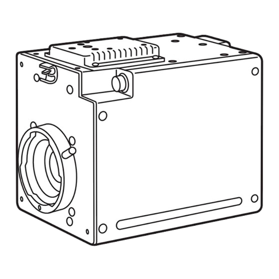
Page 31: Outside Dimension Diagram
Outside Dimension Diagram 4-3/8q (110) 6-5/16q (160) 5/8q (15) ( ): mm B R E A K E R Z O O M / F O C U S S D I O U T 1 / F 13/16q (20) -
Page 32: Specifications & Accessories
Specifications & Accessories _ Specifications Supply voltage: DC 12V (supplied from D-SUB 15 pins) Power consumption: 22 W indicates safety information. Image pickup device: System: Resolving optical system: Optical filter: Lens mount: Output spec.: Sensitivity: S/N: Horizontal frequency: Vertical frequency: Ambient temp. - Page 36 PANASONIC BROADCAST & TELEVISION SYSTEMS COMPANY UNIT COMPANY OF MATSUSHITA ELECTRIC CORPORATION OF AMERICA Executive Office: One Panasonic Way 4E-7, Secaucus, NJ 07094 (201) 348-7000 EASTERN ZONE: One Panasonic Way 4E-7, Secaucus, NJ 07094 (201) 348-7621 Southeast Region: 1225 Northbrook Parkway, Ste 1-160, Suwanee, GA 30024 (770) 338-6835...
Need help?
Do you have a question about the AK-HC910 and is the answer not in the manual?
Questions and answers