Table of Contents
Advertisement
Available languages
Available languages
Quick Links
ServeMaster
User Manual
User Manual
User Manual
User Manual
User Manual
Benutzerhandbuch
Benutzerhandbuch
Benutzerhandbuch
Benutzerhandbuch
Benutzerhandbuch
Manuel d'Utilisateur
Manuel d'Utilisateur
Manuel d'Utilisateur
Manuel d'Utilisateur
Manuel d'Utilisateur
Manual del Usario
Manual del Usario
Manual del Usario
Manual del Usario
Manual del Usario
Manuale dell'Utente
Manuale dell'Utente
Manuale dell'Utente
Manuale dell'Utente
Manuale dell'Utente
1600MV • 3300MV • 4600MV
1600MV • 3300MV • 4600MV
1600MV • 3300MV • 4600MV
1600MV • 3300MV • 4600MV
1600MV • 3300MV • 4600MV
1600HV • 3300HV • 4600HV
1600HV • 3300HV • 4600HV
1600HV • 3300HV • 4600HV
1600HV • 3300HV • 4600HV
1600HV • 3300HV • 4600HV
Advertisement
Chapters
Table of Contents

Summary of Contents for IBC SOLAR ServeMaster 1600MV
- Page 1 ServeMaster User Manual User Manual User Manual User Manual User Manual Benutzerhandbuch Benutzerhandbuch Benutzerhandbuch Benutzerhandbuch Benutzerhandbuch Manuel d’Utilisateur Manuel d’Utilisateur Manuel d’Utilisateur Manuel d’Utilisateur Manuel d’Utilisateur Manual del Usario Manual del Usario Manual del Usario Manual del Usario Manual del Usario Manuale dell’Utente Manuale dell’Utente Manuale dell’Utente...
- Page 2 Choice of Language - Sprachauswahl - Choix de la langue - Selección de idioma - Scelta della lingua Page English UK Seite Deutsch Page Francois Página Español Pagina Italiano C00410346-02...
-
Page 3: Table Of Contents
Contents Contents 1. Introduction Introduction 2. Function Description Definition of Operation Modes PV Configuration LEDs Display Overview Menu Section A Overview Menu Section B 3. Troubleshooting Troubleshooting Inverter Event Messages 4. Maintenance Maintenance Cleaning the Cabinet Cleaning the Heatsink C00410346-02... -
Page 4: Introduction
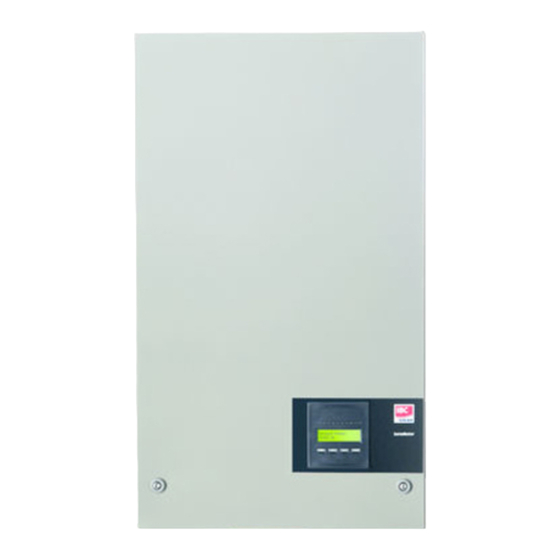
1. Introduction 1.1. Introduction This manual describes IBC Solar photovoltaic inverters. These products are among the most tech- nologically advanced and efficient inverters on the market and are designed to supply the owner with reliable solar energy for many years. -
Page 5: Function Description
2. Function Description 2. Function Description 2.1. Definition of Operation Modes The inverter has four modes: Standby mode: In standby mode, the inverter is ready to switch into connecting mode. As decision variable the input voltage of the PV generator is used. If the input voltage exceeds a preset nominal value, the inverter shifts from “standby”... -
Page 6: Leds
2. Function Description Notice that the inverter continues to produce energy in the meantime. The display readout shows the status of the test. The first line shows that this concerns the PV configuration and the second line shows which status the test is in or which configura- tion it has detected. -
Page 7: Overview Menu Section A
2. Function Description Goes one step backwards/up in the menu structure ▲ Scrolls back to the previous menu display Down Scrolls forward to the next menu display ▼ Enter New menu level or changing of settings Illustration 2.2: Display The parameters shown in the display refer to internally measured voltages and currents. The parameters shown may deviate. -
Page 8: Overview Menu Section B
2. Function Description 2.1.6. Overview Menu Section B The table below gives an overview of the menu structure. The two menu levels are clearly indicated by an arrow followed by a submenu. The values shown are only intended as examples of display texts. - Page 9 2. Function Description Menu Structure B- Continued Display Functions Description Total Derating Temperature. Shows the total amount of time the inverter Total drt. Temp. - Press OK to view has derated due to high temperature. ↳ Submenu DC1 Derating Temperature. Shows the amount of time the inverter has DC1 derate temp.
- Page 10 2. Function Description If an earthing fault occurs, the display will indicate this by a flash of the lit green LEDs. The display will change to “current event”, if it has not been operated in the past 10 minutes. The inverter will continue to produce energy.
-
Page 11: Troubleshooting
3. Troubleshooting 3. Troubleshooting 3.1. Troubleshooting Note: Remember that only trained and authorised personnel familiar with electrical systems and safety issues may work on inverters and electrical installations. In the following, the term 'Event' describes all events that prevent the inverter from operating properly. - Page 12 3. Troubleshooting Event text Description Fault Action in the event of a permanent fail- origin U 3.3 Internal power supply outside limits Inverter Service inverter U 5.0 Internal power supply outside limits Inverter Service inverter U 15.0 Internal power supply outside limits Inverter Service inverter U PV...
-
Page 13: Maintenance
4. Maintenance 4. Maintenance 4.1. Maintenance Normally, the ServeMaster outdoor inverters need no maintenance or calibration. It should be ensured, however, that the cooling is not obstructed. To ensure the functionality of the DC-switch, all switches should be switched on and off (by turning the switch to on and off positions ten times), once a year, to clean the contacts. - Page 14 Inhaltsverzeichnis Inhaltsverzeichnis 1. Einführung Einführung 2. Funktionsbeschreibung Definition der Betriebsarten PV-Konfiguration LEDs Display Überblick Menüabschnitt A Überblick Menübereich B 3. Fehlerbehebung Fehlerbehebung Wechselrichter – Ereignismeldungen 4. Wartung Wartung Reinigen des Schaltschranks Reinigen des Kühlkörpers C00410346-02...
-
Page 15: Einführung
1. Einführung 1. Einführung 1.1. Einführung Dieses Handbuch beschreibt die photovoltaischen Wechselrichter von IBC Solar. Diese Produkte zählen zu den technologisch fortschrittlichsten und effizientesten Wechselrichtern auf dem Markt und ermöglichen eine verlässliche Versorgung mit Solarenergie über viele Jahre hinweg. Abbildung 1.1: ServeMaster-Wechselrichter für den Außenbereich – mit Display CE-Kennzeichnung: Diese Kennzeichnung gibt an, dass die Geräte den gel-... -
Page 16: Funktionsbeschreibung
2. Funktionsbeschreibung 2. Funktionsbeschreibung 2.1. Definition der Betriebsarten Der Wechselrichter hat vier Betriebsarten: Bereitschaftsmodus: Im Bereitschaftsmodus ist der Wechselrichter bereit, auf den Anschlussmodus umzuschalten. Als Entscheidungsgröße wird die Eingangsspannung des PV-Generators herangezogen. Übersteigt die Eingangsspannung einen definierten Sollwert, wechselt der Wechselrichter aus dem Bereitschafts- modus in den Anschlussmodus oder leitet bei Verringerung der PV-Spannung in die Betriebsart „AUS“... -
Page 17: Leds
2. Funktionsbeschreibung Für ServeMaster 4600 müssen zwei von drei DC-Modulen für den Test mit Strom versorgt werden. Steht nicht genügend PV-Energie zur Versorgung von zwei Modulen zur Verfügung, wird die Prüfung verschoben, bis genügend PV-Energie für den Betrieb des zweiten DC-Moduls vorliegt. Dabei erzeugt der Wechselrichter weiterhin Energie. -
Page 18: Display
2. Funktionsbeschreibung 2.1.4. Display Der Benutzer hat über das integrierte Display auf der Vorderseite des Wechselrichters Zugang zu allen Informationen über das PV-System und den Wechselrichter. Befindet sich der Wechselrichter im OFF-Betrieb (bei Nacht), ist es möglich, den Wechselrichter durch eine Betätigung der linken Taste (ESC-Taste) am Display zu aktivieren. -
Page 19: Überblick Menübereich B
2. Funktionsbeschreibung 2.1.6. Überblick Menübereich B Die nachfolgende Tabelle bietet einen Überblick der Menüstruktur. Die beiden Menüebenen wer- den durch einen Pfeil gekennzeichnet, dem ein Untermenü folgt. Die angegebenen Werte dienen nur als Beispiel für die Displaytexte. Menüstruktur B Displayfunktionen Beschreibung Zeigt die aktuelle Betriebsart des Wechselrichters an. - Page 20 2. Funktionsbeschreibung Menüstruktur B – Fortsetzung Displayfunktionen Beschreibung Temperaturminderung insgesamt. Zeigt den Gesamtwert des Zeitraums Temp. mind. tot. – Zum Anzeigen OK drücken an, über den der Wechselrichter aufgrund von hohen Temperaturen ge- drosselt wurde. ↳ Untermenü Temperaturminderung DC1. Zeigt den Zeitraum an, über den der Wech- DC1 Temp.mind.
- Page 21 2. Funktionsbeschreibung Wurde der Wechselrichter aufgrund eines Fehlers vom Netz getrennt, beginnt die rote LED zu blinken, und die Anzeige wechselt automatisch in das Menü B, in dem das Ereignis angezeigt wird. Tritt ein Erdungsfehler auf, wird dieser am Display durch Blinken der grünen LEDs angezeigt. Die Anzeige wechselt zu „Aktuelles Ereignis“, wenn in den letzten zehn Minuten keine Aktualisierung erfolgt ist.
-
Page 22: Fehlerbehebung
3. Fehlerbehebung 3. Fehlerbehebung 3.1. Fehlerbehebung Anmerkung: Beachten Sie, dass alle Arbeiten an Wechselrichtern und elektrischen Installationen nur von geschultem und autorisiertem, mit elektrischen Anlagen und Sicherheitsfragen vertrautem Per- sonal vorgenommen werden dürfen. Im Folgenden beschreibt der Ausdruck „Ereignis“ alle Ereignisse, die den Wechselrichter daran hindern, ordnungsgemäß... - Page 23 3. Fehlerbehebung Ereignistext Beschreibung Fehler- Maßnahme bei einem dauerhaften Feh- ursache U 3,3 Interne Stromversorgung außerhalb Wechsel- Den Wechselrichter warten der Grenzwerte richter U 5,0 Interne Stromversorgung außerhalb Wechsel- Den Wechselrichter warten der Grenzwerte richter U 15,0 Interne Stromversorgung außerhalb Wechsel- Den Wechselrichter warten der Grenzwerte...
-
Page 24: Wartung
4. Wartung 4. Wartung 4.1. Wartung Die ServeMaster Wechselrichter für den Außenbereich erfordern im Normalfall keine Wartung oder Kalibrierung. Es ist nur auf eine unbehinderte Kühlung zu achten. Um die Funktionalität des DC-Schalters sicherzustellen, müssen einmal jährlich alle Schalter aus- und eingeschaltet werden (hierzu den Schalter zehnmal ein- und ausschalten), um die Kontakte zu reinigen. - Page 25 Table des matières Table des matières 1. Introduction Introduction 2. Description de fonction Définition des modes de fonctionnement Configuration PV Écran Section A du menu de présentation Section B du menu de présentation 3. Dépannage Dépannage Messages d'événements de l'onduleur 4.
-
Page 26: Introduction
1. Introduction 1.1. Introduction Ce manuel décrit des onduleurs photovoltaïques IBC Solar. Ces produits comptent parmi les on- duleurs les plus efficaces et sophistiqués du marché. Leur conception assure pendant de longues années à leur propriétaire une alimentation en énergie solaire fiable. -
Page 27: Description De Fonction
2. Description de fonction 2. Description de fonction 2.1. Définition des modes de fonctionnement L'onduleur dispose de quatre modes : Mode Veille : En mode Veille, l'onduleur est prêt à basculer en mode Connexion. La tension d'entrée du géné- rateur PV constitue la variable déterminante. Si la tension d'entrée excède une valeur nominale préréglée, l'onduleur passe du mode Veille au mode Connexion ou continue à... -
Page 28: Led
2. Description de fonction est reporté jusqu'à l'obtention de la puissance suffisante pour pouvoir faire fonctionner le deu- xième module CC. Noter cependant que pendant ce temps l'onduleur continue à produire de l'énergie. L'afficheur indique l'état du test. La première ligne mentionne la configuration PV et la se- conde l'état du test ou la configuration détec- tée. -
Page 29: Écran
2. Description de fonction 2.1.4. Écran Grâce à l'écran intégré à l'avant de l'onduleur, l'utilisateur peut accéder à toutes les informations relatives au système PV et à l'onduleur. Si l'onduleur se trouve en mode OFF (la nuit), il peut cependant être activé en appuyant sur le bouton gauche (ESC). Echap Revient en arrière ou remonte d'un niveau dans la structure de menu ▲... -
Page 30: Section B Du Menu De Présentation
2. Description de fonction 2.1.6. Section B du menu de présentation Le tableau ci-dessous fournit un aperçu de la structure de menu. Les deux niveaux de menu sont clairement indiqués par une flèche suivie d'un sous-menu. Les valeurs indiquées ne sont données qu'à... - Page 31 2. Description de fonction Structure de menu B - suite Fonctions d'affichage Description Dégradation température totale. Affiche le temps total pendant lequel l'on- Réduc puiss. tot - App.OK pour voir duleur a fonctionné en réduction en raison d'une température élevée. ↳...
- Page 32 2. Description de fonction Si l'onduleur est déconnecté du réseau suite à une panne, la LED rouge commence à clignoter et l'écran bascule automatiquement sur le menu B qui affiche l'événement. Si un défaut de mise à la terre survient, l'écran le mentionnera par un clignotement de la LED verte allumée.
-
Page 33: Dépannage
3. Dépannage 3. Dépannage 3.1. Dépannage Remarque: Ne pas oublier que seul du personnel formé, autorisé et expérimenté en matière de systèmes électriques et de sécurité est habilité à intervenir sur des onduleurs et des installations élec- triques. Dans les chapitres suivants, le terme « Événement » décrit tous les événements qui empêchent le bon fonctionnement de l'onduleur. - Page 34 3. Dépannage Message de l'événe- Description Origine Action en cas de panne permanente ment du défaut U 3.3 Alimentation électrique interne hors li- Onduleur Intervenir sur l'onduleur mites U 5.0 Alimentation électrique interne hors li- Onduleur Intervenir sur l'onduleur mites U 15.0 Alimentation électrique interne hors li- Onduleur...
-
Page 35: Maintenance
4. Maintenance 4. Maintenance 4.1. Maintenance Normalement, les onduleurs d'extérieur ServeMaster ne nécessitent ni maintenance, ni étalonna- ge. Cependant, s'assurer que le système de refroidissement n'est pas obstrué. Pour assurer le bon fonctionnement de l'interrupteur CC, tous les interrupteurs doivent être allu- més puis éteints (en mettant l'interrupteur en position allumée puis éteinte dix fois) une fois par an pour nettoyer les contacts. - Page 36 Índice Índice 1. Introducción Introducción 2. Descripción de las funciones Definición de los modos de funcionamiento Configuración PV Indicadores LED Display Información general sobre la sección A del menú Información general sobre la sección B del menú 3. Resolución de problemas Resolución de problemas Mensajes de incidencias en el inversor 4.
-
Page 37: Introducción
1. Introducción 1. Introducción 1.1. Introducción Este manual describe inversores fotovoltaicos IBC Solar. Estos productos se encuentran entre los inversores más avanzados tecnológicamente del mercado y están diseñados para proporcionar al propietario energía solar fiable durante muchos años. Ilustración 1.1: ServeMaster Inversor exterior con display Señal CE: certifica el cumplimiento del equipo con la reglamentación aplicable... -
Page 38: Descripción De Las Funciones
2. Descripción de las funciones 2. Descripción de las funciones 2.1. Definición de los modos de funcionamiento El inversor presenta cuatro modos de funcionamiento: Modo de espera: En el «modo de espera», el inversor está listo para pasar al «modo de conexión». Aunque puede cambiarse, el inversor utiliza por defecto el voltaje de entrada del generador PV. -
Page 39: Indicadores Led
2. Descripción de las funciones dulos, la prueba se aplaza hasta que haya suficiente energía eléctrica PV para poner en marcha el segundo módulo de CC. Tenga en cuenta que el inversor sigue produciendo energía durante todo este tiempo. La lectura del display muestra el estado de la prueba. -
Page 40: Display
2. Descripción de las funciones o en las conexiones periféricas, como puede ser la desconexión de la red, el indicador LED rojo empieza a parpadear. 2.1.4. Display A través del display integrado en el frontal del inversor, el usuario tiene acceso a toda la infor- mación del sistema PV y del inversor. -
Page 41: Información General Sobre La Sección B Del Menú
2. Descripción de las funciones 2.1.6. Información general sobre la sección B del menú En la tabla que aparece a continuación se presenta de forma breve la estructura del menú. Los dos niveles del menú quedan claramente diferenciados por una flecha seguida de un submenú. Los valores se presentan únicamente a modo de ejemplo de los textos del display. - Page 42 2. Descripción de las funciones Estructura del menú B: continuación Funciones del display Descripción Reducción de potencia total por temperatura. Muestra el tiempo total durante el cual el inversor Reducción de potencia total por temperatura: pulse «OK» para consultar ha reducido su potencia debido a las altas tempe- raturas.
- Page 43 2. Descripción de las funciones Si el inversor está conectado a la red y no se ha pulsado ninguna tecla durante 3 minutos, el display pasará automáticamente a la opción de producción de hoy. Cuando comienza y termina la prueba de configuración PV, el display pasa temporalmente al menú B para mostrar el estado de la prueba de configuración PV.
-
Page 44: Resolución De Problemas
3. Resolución de problemas 3. Resolución de problemas 3.1. Resolución de problemas Note: Recuerde que los inversores y las instalaciones eléctricas solo deben ser manipulados por per- sonal autorizado, debidamente capacitado y familiarizado con los sistemas eléctricos y las cuestiones de seguridad. En lo sucesivo, el término «incidencia»... - Page 45 3. Resolución de problemas Texto de la inciden- Descripción Origen Medidas necesarias en caso de fallo del fallo permanente U 3,3 Suministro de energía interna fuera de Inversor Repare el inversor los límites permitidos U 5,0 Suministro de energía interna fuera de Inversor Repare el inversor los límites permitidos...
-
Page 46: Mantenimiento
4. Mantenimiento 4. Mantenimiento 4.1. Mantenimiento Normalmente, los inversores para exteriores ServeMaster no necesitan mantenimiento ni calibra- ción. Sin embargo, es importante comprobar que no haya nada que obstruya el sistema de refrigeración. Para garantizar la funcionalidad del interruptor de CC, deberían activarse y desactivarse todos los interruptores (cambiando el interruptor a la posición de activación y desactivación diez veces) una vez al año, para limpiar los contactos. - Page 47 Sommario Sommario 1. Introduzione Introduzione 2. Descrizione delle Funzionalità Definizione delle modalità di funzionamento Configurazione FV Display Panoramica Sezione Menu A Panoramica sulla Sezione Menu B 3. Risoluzione dei problemi Risoluzione dei problemi Messaggi di evento dell’inverter 4. Manutenzione Manutenzione Pulizia del Cabinet Pulizia del Dissipatore di Calore C00410346-02...
-
Page 48: Introduzione
1. Introduzione 1.1. Introduzione Questo manuale offre una descrizione degli inverter fotovoltaici IBC Solar. Questi prodotti sono considerati gli inverter più efficienti e tecnologicamente avanzati presenti sul mercato e sono pro- gettati per fornire all'utente un supporto affidabile di energia solare che duri molti anni. -
Page 49: Descrizione Delle Funzionalità
2. Descrizione delle Funzionalità 2. Descrizione delle Funzionalità 2.1. Definizione delle modalità di funzionamento L’inverter ha quattro modalità di funzionamento: Modalità standby: Nella modalità di attesa, l'inverter è pronto a commutare alla modalità di connessione. Come va- riabile decisionale si utilizza la tensione di ingresso del generatore FV. Se la tensione di ingresso supera un valore nominale preimpostato, l'inverter passa da “attesa”... -
Page 50: Led
2. Descrizione delle Funzionalità a quando non vi è sufficiente potenza FV disponibile per far funzionare anche il secondo modulo Nel frattempo l'inverter continuerà a produrre energia. La dicitura sul display mostra lo stato del test. La prima riga indica che ciò riguarda la confi- gurazione FV e la seconda riga indica lo stato in cui si trova attualmente il test o quale con- figurazione ha rilevato. -
Page 51: Display
2. Descrizione delle Funzionalità 2.1.4. Display L'utente ha accesso a tutte le informazioni relative al sistema FV e all'inverter grazie al display integrato nella parte anteriore dell'inverter. Quando l'inverter è in modalità OFF (di notte), è pos- sibile attivare l'inverter premendo il pulsante sinistro (ESC). Va un passo indietro/avanti nella struttura dei menu ▲... -
Page 52: Panoramica Sulla Sezione Menu B
2. Descrizione delle Funzionalità 2.1.6. Panoramica sulla Sezione Menu B La tabella in basso offre una panoramica della struttura del menu. I due livelli di menu sono chiaramente indicati da una freccia seguita da un sottomenu. I valori indicati devono essere intesi unicamente come esempi di testi visualizzati. - Page 53 2. Descrizione delle Funzionalità Struttura Menu B - Prosegue Funzioni visualizzate Descrizione: Degradazione totale temperatura. Mostra la quantità totale di tempo Declass. totale: Temp. - Premere OK per visualizzare nel quale l'inverter è stato degradato a causa dell'alta temperatura. ↳ Sottomenu Degradazione temperatura CC1.
- Page 54 2. Descrizione delle Funzionalità Se si verifica un guasto di terra, il display lo indicherà tramite un lampeggiamento dei LED verdi accesi. Il display passerà a "evento attuale" se non è stato usato negli ultimi 10 minuti. L'inverter continuerà a produrre energia. Se si verifica un guasto di terra, ciò non indica un errore dell'inverter ed è...
-
Page 55: Risoluzione Dei Problemi
3. Risoluzione dei problemi 3. Risoluzione dei problemi 3.1. Risoluzione dei problemi Note: È necessario tenere a mente che solo il personale addestrato e autorizzato, competente su sistemi elettrici e questioni legate alla sicurezza, può lavorare sugli inverter e le installazioni elettriche. - Page 56 3. Risoluzione dei problemi Testo evento Descrizione Origine Azione in caso di guasto permanente guasto U 3.3 Alimentazione elettrica interna oltre i li- Inverter Revisionare l'inverter miti U 5.0 Alimentazione elettrica interna oltre i li- Inverter Revisionare l'inverter miti U 15.0 Alimentazione elettrica interna oltre i li- Inverter Revisionare l'inverter...
-
Page 57: Manutenzione
4. Manutenzione 4. Manutenzione 4.1. Manutenzione Di norma gli inverter ServeMaster non hanno necessità di manutenzione o calibrazione. Tuttavia è necessario assicurare che il raffreddamento non sia ostruito. Per assicurare la funzionalità dell'interruttore di sconnessione CC, tutti gli interruttori dovrebbero essere accessi e spenti (commutando l'interruttore per dieci volte su On e Off) una volta all'anno al fine di pulire i contatti. - Page 58 IBC SOLAR AG IBC SOLAR AG IBC SOLAR AG IBC SOLAR AG IBC SOLAR AG Am Hochgericht 10 96231 Bad Staffelstein Fon: +49 9573 9224-0 Fax: +49 9573 9224-111 www.ibc-solar.com Danfoss can accept no responsibility for possible errors in catalogues, brochures and other printed material. Danfoss reserves the right to alter its products without notice. This also applies to products already on order provided that such alterations can be made without subsequential changes being necessary in specifications already agreed.
Need help?
Do you have a question about the ServeMaster 1600MV and is the answer not in the manual?
Questions and answers