Table of Contents
Advertisement
Quick Links
Operating instructions
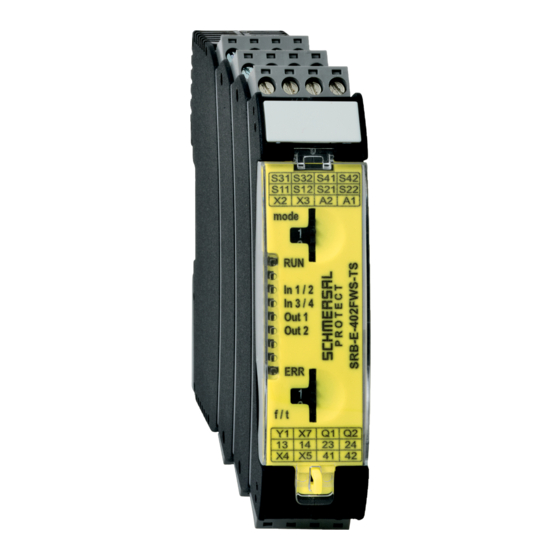
Fail-safe delay timer / Standstill monitor
Operating instructions. . . . . . . . . . . .pages 1 to 14
EN
Original
Content
1
About this document
1.1 Function . . . . . . . . . . . . . . . . . . . . . . . . . . . . . . . . . . . . . . . . . . . . . .1
1.2 Target group: authorised qualified personnel. . . . . . . . . . . . . . . . . .1
1.3 Explanation of the symbols used . . . . . . . . . . . . . . . . . . . . . . . . . . .1
1.4 Appropriate use . . . . . . . . . . . . . . . . . . . . . . . . . . . . . . . . . . . . . . . .2
1.5 General safety instructions . . . . . . . . . . . . . . . . . . . . . . . . . . . . . . .2
1.6 Warning about misuse . . . . . . . . . . . . . . . . . . . . . . . . . . . . . . . . . . .2
1.7 Exclusion of liability . . . . . . . . . . . . . . . . . . . . . . . . . . . . . . . . . . . . .2
2
2.1 Ordering code . . . . . . . . . . . . . . . . . . . . . . . . . . . . . . . . . . . . . . . . .2
2.2 Special versions. . . . . . . . . . . . . . . . . . . . . . . . . . . . . . . . . . . . . . . .2
2.3 Purpose . . . . . . . . . . . . . . . . . . . . . . . . . . . . . . . . . . . . . . . . . . . . . .2
2.4 Technical data . . . . . . . . . . . . . . . . . . . . . . . . . . . . . . . . . . . . . . . . .3
2.5 Derating / electrical lifespan of safety contacts . . . . . . . . . . . . . . . .3
2.6 Safety classification . . . . . . . . . . . . . . . . . . . . . . . . . . . . . . . . . . . . .4
3
3.1 General mounting instructions . . . . . . . . . . . . . . . . . . . . . . . . . . . . .4
3.2 Dimensions . . . . . . . . . . . . . . . . . . . . . . . . . . . . . . . . . . . . . . . . . . .4
4
4.1 General information for electrical connection. . . . . . . . . . . . . . . . . .4
4.2 Coding of connecting terminals . . . . . . . . . . . . . . . . . . . . . . . . . . . .4
5
5.1 Description of the terminals and LED indications . . . . . . . . . . . . . .5
5.2 Adjustable applications . . . . . . . . . . . . . . . . . . . . . . . . . . . . . . . . . .6
5.3 Changing setting or application . . . . . . . . . . . . . . . . . . . . . . . . . . . .6
6
6.1 LED indications . . . . . . . . . . . . . . . . . . . . . . . . . . . . . . . . . . . . . . . .7
6.2 Malfunctions. . . . . . . . . . . . . . . . . . . . . . . . . . . . . . . . . . . . . . . . . . .7
6.3 Warnings standstill monitoring function . . . . . . . . . . . . . . . . . . . . . .7
7
7.1 Application example fail-safe delay timer. . . . . . . . . . . . . . . . . . . . .8
7.2 Application examples safe standstill monitoring . . . . . . . . . . . . . . .9
7.4 Start configuration safety guard monitoring . . . . . . . . . . . . . . . . . .10
7.5 Sensor configuration . . . . . . . . . . . . . . . . . . . . . . . . . . . . . . . . . . .10
8
8.1 Commissioning . . . . . . . . . . . . . . . . . . . . . . . . . . . . . . . . . . . . . . . 11
8.2 Functional testing. . . . . . . . . . . . . . . . . . . . . . . . . . . . . . . . . . . . . . 11
8.3 Behaviour in the case of faults. . . . . . . . . . . . . . . . . . . . . . . . . . . . 11
8.4 Setting report . . . . . . . . . . . . . . . . . . . . . . . . . . . . . . . . . . . . . . . . . 11
8.5 Maintenance . . . . . . . . . . . . . . . . . . . . . . . . . . . . . . . . . . . . . . . . .12
9
9.1 Disassembly. . . . . . . . . . . . . . . . . . . . . . . . . . . . . . . . . . . . . . . . . .12
9.2 Disposal . . . . . . . . . . . . . . . . . . . . . . . . . . . . . . . . . . . . . . . . . . . . .12
10.1 Wiring/circuit information . . . . . . . . . . . . . . . . . . . . . . . . . . . . . . .12
1. About this document
1.1 Function
This operating instructions manual provides all the information you
need for the mounting, set-up and commissioning to ensure the safe
operation and disassembly of the safety-monitoring module. The
operating instructions must be available in a legible condition and
a complete version in the vicinity of the device.
1.2 Target group: authorised qualified personnel
All operations described in this operating instructions manual must
be carried out by trained specialist personnel, authorised by the plant
operator only.
Please make sure that you have read and understood these operating
instructions and that you know all applicable legislations regarding
occupational safety and accident prevention prior to installation and
putting the component into operation.
The machine builder must carefully select the harmonised standards
to be complied with as well as other technical specifications for the
selection, mounting and integration of the components.
1.3 Explanation of the symbols used
Information, hint, note:
This symbol is used for identifying useful additional information.
Caution: Failure to comply with this warning notice could
lead to failures or malfunctions.
Warning: Failure to comply with this warning notice could
lead to physical injury and/or damage to the machine.
EN
SRB-E-402FWS-TS
1
Advertisement
Table of Contents

Subscribe to Our Youtube Channel
Summary of Contents for schmersal SRB-E-402FWS-TS
-
Page 1: Table Of Contents
Operating instructions Fail-safe delay timer / Standstill monitor SRB-E-402FWS-TS Wiring examples 7.1 Application example fail-safe delay timer.....8 7.2 Application examples safe standstill monitoring ....9 7.3 Start configuration, time monitoring / standstill monitoring . -
Page 2: Appropriate Use
Fail-safe delay timer / Standstill monitor SRB-E-402FWS-TS 2. Product description 1.4 Appropriate use The Schmersal range of products is not intended for private consumers. 2.1 Ordering code The products described in these operating instructions are developed This operating instructions manual applies to the following types: to execute safety-related functions as part of an entire plant or machine. -
Page 3: Technical Data
Operating instructions Fail-safe delay timer / Standstill monitor SRB-E-402FWS-TS To determine the Performance Level (PL) to EN ISO 13849-1 of the Semi-conductor outputs: entire safety function (e.g. sensor, logic, actuator), an assessment of all Switching capacity of the safety outputs: Q1/Q2: max. -
Page 4: Safety Classification
Operating instructions Fail-safe delay timer / Standstill monitor SRB-E-402FWS-TS 4. Electrical connection 2.6 Safety classification 2.6.1 Safety classification of semi-conductor output 4.1 General information for electrical connection Standards: EN ISO 13849-1, IEC 61508, EN 62061 The electrical connection may only be carried out by Category: authorised personnel in a de-energised condition. -
Page 5: Operating Principle And Settings
Operating instructions Fail-safe delay timer / Standstill monitor SRB-E-402FWS-TS 5. Operating principle and settings Fail-safe delay timer function t < t Pull-in delay 5.1 Description of the terminals and LED indications Function Function Operating voltage Operating voltage OK + 24 VDC RUN mode <5s... -
Page 6: Adjustable Applications
Operating instructions Fail-safe delay timer / Standstill monitor SRB-E-402FWS-TS 5.2 Adjustable applications Adjustable applications standstill monitoring / safety guard monitoring: Rotary switch (mode) Rotary knob f / t Safety guard monitoring configuration Pos. Start / Reset Cross-wire Contact con- Configuration Pos. -
Page 7: Diagnostic
Operating instructions Fail-safe delay timer / Standstill monitor SRB-E-402FWS-TS 6. Diagnostic 6.2 Malfunctions Malfunctions and fault causes are displayed with the ERR-LEDs via 6.1 LED indications short and long flashing signals Function Display type LED + Error cause Long Short... -
Page 8: Wiring Examples
Operating instructions Fail-safe delay timer / Standstill monitor SRB-E-402FWS-TS 7. Wiring examples 7.1 Application example fail-safe delay timer Two-channel operation with Start function +24 VDC 0 VDC S31 S41 Clock Safety Clock Safety Outputs Inputs Outputs Inputs Signalling Safety Outputs... -
Page 9: Application Examples Safe Standstill Monitoring
Operating instructions Fail-safe delay timer / Standstill monitor SRB-E-402FWS-TS 7.2 Application examples safe standstill monitoring Two-channel operation with level monitoring and Start function +24 VDC 0 VDC S31 S41 S1: Additional standstill signal Clock Safety Clock Safety Outputs Inputs Outputs... -
Page 10: Start Configuration, Time Monitoring / Standstill Monitoring
Operating instructions Fail-safe delay timer / Standstill monitor SRB-E-402FWS-TS 7.3 Start configuration, time monitoring / standstill monitoring 7.4.3 Feedback circuit 7.3.1 Start/Autostart • Suitable for increase in capacity or number of contacts by means of • The safety outputs can be activated after the switch-on delay has contactors or relays with positive-guided contacts. -
Page 11: Set-Up And Maintenance
Operating instructions Fail-safe delay timer / Standstill monitor SRB-E-402FWS-TS 8. Set-up and maintenance Two-channel signal processing with standstill signal (Category 3 – PL d to EN ISO 13849-1 possible) 8.1 Commissioning The safety relay module features protection class IP54 for installation in... -
Page 12: Maintenance
Operating instructions Fail-safe delay timer / Standstill monitor SRB-E-402FWS-TS 10. Appendix 8.5 Maintenance A regular visual inspection and functional test, including the following steps, is recommended: 10.1 Wiring/circuit information 1. Check the correct fixing of the safety-monitoring module 2. Check the cable for damages Two-channel signal processing with level monitoring 3. -
Page 13: Eu Declaration Of Conformity
Fail-safe delay timer / Standstill monitor SRB-E-402FWS-TS EU Declaration of conformity EU Declaration of conformity Original K.A. Schmersal GmbH & Co. KG Möddinghofe 30 42279 Wuppertal Germany Internet: www.schmersal.com We hereby certify that the hereafter described components both in their basic design and construction conform to the applicable European Directives. - Page 14 K.A. Schmersal GmbH & Co. KG Möddinghofe 30, 42279 Wuppertal Germany Phone: +49 202 6474-0 Telefax: +49 202 6474-100 E-Mail: info@schmersal.com Internet: www.schmersal.com...
Need help?
Do you have a question about the SRB-E-402FWS-TS and is the answer not in the manual?
Questions and answers