
Summary of Contents for All-Star Products RP-40 Series
- Page 1 OPERATING SERVICE MAINTENANCE MANUAL ALL-STAR ROCKING PISTON COMPRESSOR AND VACUUM PUMP Registered by one or more of these standards agency RoHS 9001 Compliant...
-
Page 2: Safety Rules
Read through carefully and understand these instructions before use. Contact your supplier or Information All-Star Products Tel 901-755-9613 www.all-star-usa.com Have the pump model and serial numbers when ordering parts or when contacting All-Star or your supplier. Read the Safety Rules below before working on the pump. -
Page 3: Connection Diagram
Connection Diagram Note: The intake (suction) and the discharge piping should not be smaller than the connections in the unit. The piping can be a larger diameter. If the unit is used in a network arrangement with other pumps or compressors, the diameter of the piping should not be less than the total surface area of the total number of pumps connected in the network. - Page 4 COMMISSIONING This pump and compressor is to be used for pumping DANGER non-aggressive gasses (air) containing no more that 22% oxygen. This unit is not approved for nor should be used for explosive or toxic gasses. RISK OF BURNS - DO NOT TOUCH WARNING The surface temperature of the machine can reach 80 Deg C (175 Deg F) when operating at full load conditions.
-
Page 5: Electrical Connection
ELECTRICAL CONNECTION The power supply must be the same voltage and frequency as listed on the nameplate. The motor is a single phase, capacitor type and it has one cable connection. Connect the incoming power two conductors to the motor terminals and connect the earth (ground) wire to the earth terminal. - Page 6 Servicing the Head, Valve Plate Assembly and Connecting Rod and Bearing Assembly - Figure 1 Note: The head would only need to be replaced if it is visibly damaged. Parts Required: - Head if damaged - Head gasket - Valve plate O-ring - Complete valve plate assembly or individual flapper valves - Flapper valve screw (s) if replacing...
- Page 7 Removing Flapper Valves Note: It is recommended that you replace one flapper valve at a time. This will help to simplify the repair process and correctly orient the flapper valves in the valve plate. 1. If you are replacing a flapper valve on the topside of he valve plate (the side facing the head), remove the flapper valve screw (1).
- Page 8 Removing Flapper Valves (continued) 5. Place a valve restraint (3) over the flapper valve 6. Place a valve keeper strip (4) over the valve restraint, observing that the restraint’s radium is facing the valve plate and oriented as shown in Figure 3. 7.
- Page 9 Replacing A Flapper Valve On The Bottom Side Of The Valve Plate 1. To replace a flapper valve on the bottom side of the valve plate (side facing the pump housing), remove the flapper valve screw (1), lift off the valve keeper strip (2). 2.
- Page 10 Servicing Connecting Rod and Eccentric Assemblies Note: Refer to the Preventative Maintenance and Troubleshooting guide in this manual to determine whether a compete connecting rod assembly, or it’s component parts or an eccentric needs to be serviced. Components Required 1. Connecting rod assembly, piston cups and sleeves. 2.
- Page 11 Removing The Connecting Rod And Eccentric Assemblies (cont’d) 2. Turn the motor shaft to align the eccentric setscrew, the connecting rod screw separately and with the hole of the housing. See Figure 6 for location of access hole. FIGURE 6 Eccentric screw access...
- Page 12 Removing The Connecting Rod And Eccentric Assemblies (cont’d) 3. Slide the eccentric bearing assembly straight off the shaft. FIGURE 7...
- Page 13 Removing The Connecting Rod And Eccentric Assemblies (cont’d) 4. Slide and rotate the connecting rod, remove it from the housing. Remove the connecting rod and piston from the housing. FIGURE 8...
- Page 14 Removing The Connecting Rod And Eccentric Assemblies (cont’d) 4. Slide and rotate the connecting rod, remove it from the housing. Remove the connecting rod and piston from the housing. Note: Do not damage the piston cup (4) when removing the connecting rod assembly from the pump housing.
- Page 15 Rebuilding Connecting Rod Assemblies If you are rebuilding the connecting rod assembly using component parts, follow the procedure below. When replacing the piston cup (4), be sure to replace the sleeve (1) at the same time. Please the connecting rod in a fixture before attempting to remove the retainer screw.
- Page 16 Assembly Of The Connecting Rod To The Pump 1. Put cylinder sleeve into the trough of housing keeper and make connecting rod vertical. Note: Connecting rod screw to face the housing. FIGURE 10...
- Page 17 Assembly Of The Connecting Rod To The Pump (cont’d) 2. Replace the eccentric onto the shaft and insert bearing into connecting rod bearing housing. Rotate eccentric to line up set screw with access hole in bottom of housing. Rotate main shaft and let shaft flat and eccentric screen hole line up vertically.
-
Page 18: Assembling The Pump
Assembling The Pump 1. After the connecting rod assembly and the eccentric are correctly assembled, assembly of the valve plates and O-ring should be assembled next. CAUTION: To prevent damage to the pump, never apply any sealant or lubricant to the O-rings. FIGURE 12 Bottom of valve plate... - Page 19 Assembling The Pump (cont’d) 2. Insert the valve plate gasket O-ring into the O-ring groove located on the bottom of the valve plate. 3. Position the pump housing as shown in Figure 13. Note the orientation of the power leads. NOTE: Insure the connecting rod sleeves are seated against the pump housing.
- Page 20 Assembling The Pump (cont’d) 4. Note the orientation of the valve plate assemblies. Place them on the pump housing as shown in Figure 14 FIGURE 14 T ab Valve Plate Pump Housing...
- Page 21 Assembling The Pump (cont’d) 5. Insert two new head gasket O-rings into the groove located on the bottom of the head. NOTE: Insure the valve plate is properly engaged to the housing locators. NOTE: Insure that the O-rings are fully assembled in the grooves and that they are not pinched.
- Page 22 Assembling The Pump (cont’d) 6. Place the head on the valve plate assemblies, observing the position of the air intake and exhaust ports. NOTE: Make sure the head gasket O-rings are not pinched. 7. Insert the head screws and tighten each screw in the order as shown in Figure 16, until it is snug.
-
Page 23: Troubleshooting Guide
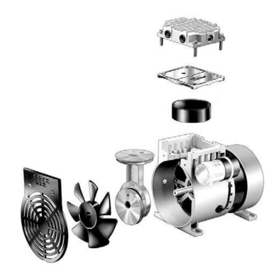
Troubleshooting Guide Motor Does Not Start Possible Cause Corrective Action Low voltage supply Insure rated voltage is applied by changing power supply. Bent motor shaft Replace entire unit Worn bearings Replace bearings Burned out fuses Check incoming power and use only “slow blow” fuses Motor starter thermal protector Check to see if thermal protector has tripped Piston jammed... - Page 24 To insure you received the correct parts, you need to provide the model number of the unit and the serial number, along with the part number as shown below.
- Page 25 To insure you received the correct parts, you need to provide the model number of the unit and the serial number, along with the part numbers as shown below.
-
Page 26: Limited Warranty
All-Star Products manufacture and/or specified by the Purchaser, is sold under only such warranty as the make thereof extends\ to All-Star Products and All-Star Products is able to enforce, but such items are not warranted by All-Star Products in anyway. All-Star Products is...
Need help?
Do you have a question about the RP-40 Series and is the answer not in the manual?
Questions and answers