Table of Contents
Advertisement
Quick Links
PARADISE
HYDRAULIC BOATLIFTS
OWNERSHIP AND INSTALLATION MANUAL
2 CYLINDER HYDRAULIC MODELS
READ CAREFULLY PRIOR TO INSTALLATION AND
USE. RETAIN THIS DOCUMENTATION.
COPYRIGHT © 2021 PARADISE DOCK & LIFT INC.
Part No. 100318 Rev. 1
Issued: 2021-06-08
MODELS
PH-6K-5
PH-6K-6
PH-8K-4
PH-8K-5
Paradise Dock & Lift Inc.
4311A 25 Ave.
Vernon, BC, Canada
paradisedocklift.com
info@paradisedocklift.com
1-888-411-3625
Page 1 of 28
V1T 1P5
Advertisement
Table of Contents

Subscribe to Our Youtube Channel
Related Manuals for Paradise Datacom PH-6K-5

Summary of Contents for Paradise Datacom PH-6K-5
- Page 1 PARADISE HYDRAULIC BOATLIFTS OWNERSHIP AND INSTALLATION MANUAL 2 CYLINDER HYDRAULIC MODELS MODELS PH-6K-5 PH-6K-6 PH-8K-4 PH-8K-5 Paradise Dock & Lift Inc. 4311A 25 Ave. Vernon, BC, Canada V1T 1P5 paradisedocklift.com info@paradisedocklift.com 1-888-411-3625 READ CAREFULLY PRIOR TO INSTALLATION AND USE. RETAIN THIS DOCUMENTATION.
-
Page 2: Table Of Contents
Paradise Hydraulic Boatlift! SPECIFICATIONS Models and specifications for Paradise hydraulic boatlifts covered in this manual are provided in the table below: Model Factory Specifications PH-6K-5 PH-6K-6 PH-8K-4 PH-8K-5 6000 lbs (2722 kg) 6000 lbs (2722 kg) 8000 lbs (3629 kg) -
Page 3: Safety Information
SAFETY INFORMATION Always read and obey all safety messages and instructions when assembling, installing or operating the boat lifting system. Boatlifts are heavy equipment that pose major hazards. Your safety is of utmost importance so if there is any misunderstanding with information contained in this manual, please contact your dealer or the manufacturer. -
Page 4: Liability Disclaimer
LIABILITY CAUTION! DISCLAIMER • During the first few operations of the lift, the weight of the watercraft may cause Installation and assembly instructions the lift to settle. Stay well away from the provided are intended for authorized lift during actuation until it is seen that the Paradise Dock &... -
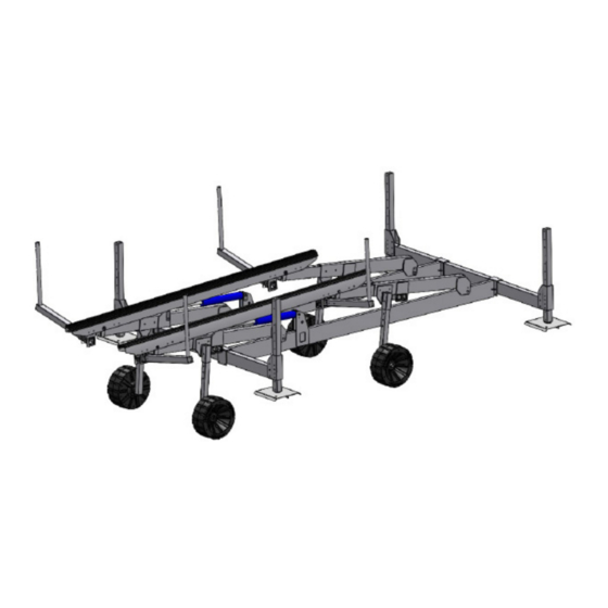
Page 5: Component Overview
COMPONENT OVERVIEW 2 Cylinder Hydraulic Boatlift Models Direction of boat entry Part Number Item Part Description PH-6K-5 PH-6K-6 PH-8K-4 PH-8K-5 Front H-Frame 100067 Rear H-Frame 100076 100091 Foot Pad 100092 Side Beam 100341 100051 Cross Beam 100088 Hydraulic Cylinder 100003... -
Page 6: Assembly Instructions
ASSEMBLY INSTRUCTIONS Tools Required: • Marine Grease • 9/16” Wrench, socket and ratchet • Rubber mallet • 3/4” Wrench, socket and ratchet • Tape Measure • 7/32” Allen Key • Pencil/Pen • Needle Nose Pliers • Torque Wrench (20-60 ft lbs range) •... - Page 7 1-D) Repeat steps A-B for the other side: 1-C) Complete one side of an H-Frame: (Rear H-Frame shown) (Rear H-Frame shown) 1-E) Repeat Steps A-D for the Front H-Frame assembly. Use the bottom set of bolt holes on the leg extensions (item 11) in order to raise the top of the leg extensions by 2.5”.
- Page 8 P/N 100431 x4 P/N 100430 x4 Rear H-Frame Front H-Frame Step 2 - Assemble the Legs (Item 3) and Foot Pads (Item 4) Hardware Required: • 8x 3/8” - Flat Washers • 4x 3/8”-16 - Kep Nuts • 4x 3/8”-16 - 3.75” Long Hex Bolts 2-A) Assemble the 4 legs and 4 foot pads: 2-B) Bolt the legs to the foot pads using the 9/16”...
- Page 9 2-C) Torque the bolted connection to 23 ft-lbs. Step 3 - Assemble the Cross Beams (Item 6) and Legs (Item 3) Hardware Required: • 8x 3/8” - Flat Washers • 4x 3/8”-16 - Kep Nuts • 4x 3/8”-16 - 4.5” Long Hex Bolts •...
- Page 10 3-B) Apply anti-seize to the bolts prior to installation. Bolt the cross beams and legs together (3/8- 16 bolts and 9/16” wrench for the legs, 1/2-13 bolts and 3/4” wrench for the cross beams): 3-C) Torque the 3/8-16 bolted connection to 23 ft-lbs and the 1/2-13 bolted connection to 56 ft-lbs.
- Page 11 4-B) Assemble the Side Beams on to the 2 cross beams: 4-C) Use the 9/16” wrenches and hardware to loosely bolt and clamp the side beams to the cross beams: Page 11 of 28 Part No. 100318 Rev. 1 Issued: 2021-06-08...
- Page 12 Step 5 - Attach H-Frames (Item 1 & 2) to Side Beams (Item 5) Hardware Required: • 4x 3/8”-16 - 3/4” Long Button Head Screws • 4x Lower Pin Assemblies (P/N 100081) • 4x 3/8” Lock Washers 5-A) Grease pin assemblies. 5-B) Use the pin assemblies to attach the H-Frames (item 1 &...
- Page 13 5-D) Tighten the hardware from step 4-C now that the H-Frames are attached. Torque the 3/8 bolts to 23 ft-lbs. Step 6 - Assemble Cylinders Hardware Required: • 4x Pin Assemblies (2x P/N 100077, 2x P/N • 4x 3/8”-16 - 3/4” Long Button Head Screws 100180) •...
- Page 14 6-A) Use the pin assemblies to attach the hydraulic cylinders (item 7) to the rear H-Frame (item 2). Use the plastic washers to space the cylinders from inside face of the aluminum lugs: P/N 100180 P/N 100077 6-B) Apply marine grease to the pins. Secure the pins using the 7/32” Allen key to tighten the 3/8” button head screws: Part No.
- Page 15 Step 7 - Install Bunks (Item 8) Hardware Required: • 4x 1” Diameter Bunk Pins • 4x 1” Flat Washers • 4x Cotter Pins - 1/8” x 2” • 8x 1” Plastic Washers (P/N 100276) 7-A) Place bunks (item 8) on H-Frame assemblies: Page 15 of 28 Part No.
- Page 16 7-B) Install bunk pins to secure bunks to H-Frame. Use plastic washers on the inside surfaces of the bunk as spacers. Use cotter pins and flat washer to secure bunk pins. Bend the end of the cotter pin with the needle nose pliers to secure the pins. Step 8 - Install Guide-Ons (Item 10) (Optional) Hardware Required: •...
- Page 17 8-A) Assemble guide-on bracket and arm and lift into position: WARNING! Note the correct locations indicated above by the check marks, incorrect installation can cause damage to the lift frame and/or bunks. 8-B) Bolt guide-ons to bunk using 3/8-16 x 6” long bolts. Apply anti seize, tighten the bolts with 9/16”...
- Page 18 8-C) Bolt the adjustable arm into place using the 3/8-16 x 4” long bolts. Apply anti seize, tighten the bolts with 9/16” wrench and torque to 23 ft-lbs. Position the arms such that they fit the boat width with a minimum 2 inch spacing on each side of the boat. Place the plastic pipe and guide-on covers over the guide-on tube.
- Page 19 9-B) Ensure that a minimum of 20” length of hose is between the top of the clip to the bottom fitting of the cylinder as indicated by the two arrows. This length is the minimum required for the hoses to not bind when the lift actuates. Step 10 - Connect Power Pack 10-A) Connect quick-connect hydraulic fittings to power pack.
- Page 20 10-B) Check tightness of the battery terminals. If the battery terminal nuts are not tight, turn the nuts one at a time until hand tight and then 1/2 turn using a wrench. Step 11 - Install Solar Panels on the Power Pack (Optional) 11-A) To install the solar panels to the power pack, first locate the orientation of the solar panel on the lid of the power pack as shown below.
- Page 21 16.3” 3” 11-B) If two solar panels are being installed, orient the solar panels as shown below with the black electrical connections approximately 2 inches apart. Mark the locations of the electrical connections and drill two 7/8” holes at the marked locations. Insert the electrical wires into the power pack and secure the solar panels using double-sided tape.
-
Page 22: Installation
INSTALLATION WARNING! Only install lift during good conditions, adverse conditions may pose a hazard during installation that may cause injury, death or property damage. Never exceed the maximum rated lift capacity. Exceeding the capacity may cause the lift to tip or fail causing injury, death or property damage. Placing the Lift Your lift should be installed with the top of the cross beams at a water depth of between 24 to 48 inches from the surface. -
Page 23: Remote Control & Controller
Leveling the Lift Use a tape measure to measure from the top of the cross beams at each of the 4 corners to the surface of the water. All measurements should be within 2 inches of each other. If they are not, adjust the leg height (leg bolt holes are in 2 inch increments) at the corner that is more than 2 inches different from the other corners. -
Page 24: Maintenance
Down Arrow: Actuates the lift downwards. Light: Actuates the light kit if optioned. This button is latching (light remains on when actuated on or off ) If your remote is not working, please check that the 2x AAA batteries are not dead and replace if necessary. Inside the power pack box, the lift also contains a hard-wired controller, the operation of the controller is described below:... - Page 25 Storage Tips The following suggestions pertain for when your lift is not in use: • When storing your boat, the lift should always be in the fully “up over centre” position. If your lift has a hydraulic leak, the boat will not drop in such a case. •...
-
Page 26: Warranty
WARRANTY Paradise Dock and Lift Inc. (“company”) warrants it’s boatlifts for non-commercial and non- governmental use for a period of • 3 years against manufacturing defects in aluminum lift frames, • 3 years against defects in material and workmanship for hydraulic components, remote control, charging systems, bunks, canopies power pack box, and accessories to the original Purchaser (“purchaser”). - Page 27 Exclusions: Product changes or damage caused by age or environment (corrosion, marine growth, heat, electrolysis) shall not constitute a defect. Additionally, this warranty does not cover or apply to the following: damages caused by or due to without limitation: collision, fire, accidents, flood, wind, ice, or any other natural disaster, act of God, abuse, misuse, overloading, improper watercraft loading, use when out of level, faulty installation or faulty assembly.
- Page 28 Paradise Dock & Lift Inc. 4311A 25 Ave. Vernon, BC, Canada V1T 1P5 paradisedocklift.com info@paradisedocklift.com 1-888-411-3625 SPECIFICATIONS & INSTRUCTIONS SUBJECT TO CHANGE WITHOUT NOTICE. COPYRIGHT © 2021 PARADISE DOCK & LIFT INC. Part No. 100318 Rev. 1 Page 28 of 28 Issued: 2021-06-08...
Need help?
Do you have a question about the PH-6K-5 and is the answer not in the manual?
Questions and answers