Advertisement
Quick Links
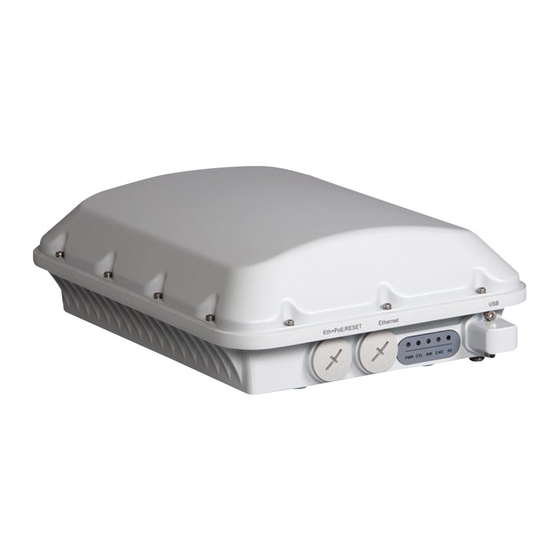
T610/T610s Mounting Bracket
Accessory Kit
Quick Setup Guide
This
Quick Setup Guide
provides step-by-step instructions on
how to field-install the Ruckus Wireless T610 access point (AP)
using the T610/T610s Mounting Bracket Accessory Kit (part
number 902-0125-0000).
The T610/T610s Mounting Bracket Accessory Kit includes two
different length Linkage Brackets, one for T610 (omni antenna
version) and one for T610s (sector antenna). If you are installing
a T610, use the longer linkage bracket (175 mm). If you are
installing a T610s, use the shorter (100 mm) linkage bracket.
For detailed information on planning the installation, performing
a site survey, and operating the AP, refer to the
Outdoor Access Point User Guide
, available at https://
support.ruckuswireless.com.
P
C
ACKAGE
ONTENTS
A complete T610/T610s Mounting Bracket Accessory Kit
includes all of the items listed below:
•
Mounting Bracket Hardware Kit (includes the following):
•
Bolt, M8 x 1.25, 50 mm long, SS (2)
•
Washer, Spring Lock, SS, DIN 127B, M8 (2)
•
Washer, Flat, SS, DIN 125A, M8 (2)
•
Clamp, Pipe, 1.5 in. to 2.5 in., +/-0.1 in. ID., SUS304 SST(4)
•
Washer, Serrated External Tooth, Lock, M8, SST (2)
•
Washer, .250, Split Lock, 18-8 SS (8)
•
Washer, .250, Flat, 8-18 SS (8)
•
Bolt, .250-28 x .50"L, Hex Head, SS (8)
•
U Joint Bracket, Aluminum, 3mm thick
•
Wall Mount Bracket, Aluminum, 3mm thick
•
AP Bracket, Aluminum, 3mm thick
•
2 Linkage Brackets (100 mm, 175 mm length):
•
For T610, use the 175 mm bracket;
•
For T610s, use the 100 mm bracket
•
Safety Cable Kit
•
This Quick Setup Guide
Copyright © 2017 Ruckus Wireless, Inc.
Published March 2017, Part Number 800-71404-001 Rev C
R
H
EQUIRED
ARDWARE AND
•
1/2" (13mm) flat-blade screwdriver or equivalent
•
No. 2 Phillips screwdriver
•
Torque wrench or torque screwdriver with sockets
•
Pipe or pole --OR-- a sturdy flat surface
•
Electric drill with drill bits and customer-supplied wall anchors,
flat washers, and hex nuts for flat-surface mount
•
Ruler
S
1: A
TEP
TTACH THE
M
B
OUNTING
RACKET
1
Position the U-joint bracket on the mounting bracket.
Figure 1:
U-joint bracket attached horizontally to the mounting bracket
A
ZoneFlex
NOTE: Mount the U-joint bracket in any direction on the mounting
bracket, preferably to allow AP azimuth adjustments. Then the AP
bracket allows AP elevation adjustments.
2
Use four 1/4-28 bolt and washer sets (A) to mount the U-joint
bracket (B) to the mounting bracket (C). Tighten the bolts to 9.5
N.m (7 ft-lbs).
3
Continue with
Step 2a: Attach the Mounting Bracket to a Flat
Surface
or
Step 2b: Attach the Mounting Bracket to a Metal
Pole
.
S
2
: A
TEP
A
TTACH THE
F
S
LAT
URFACE
1
Place the mounting bracket at the location on the flat surface
where you want to mount the AP. Use the holes on the mounting
bracket as a template to mark the locations of the mounting
holes.
Figure 2:
Mounting bracket flat surface holes
T
OOLS
U-J
B
OINT
RACKET TO THE
C
B
M
B
OUNTING
RACKET TO A
2
Remove the mounting bracket from the flat surface.
3
Drill holes required for the mounting hardware.
NOTE: The hardware required for mounting to a wall is not
included in the mounting kit.
4
Attach the mounting bracket to the flat surface using the
mounting hardware.
5
Using the mounting hardware instructions, tighten the hardware to
secure the mounting bracket.
Step 3: Mount the Linkage Bracket to the U-
6
Continue with
Joint Bracket
.
S
2
: A
M
TEP
B
TTACH THE
OUNTING
M
P
ETAL
OLE
1
Insert the open end of one steel clamp into the upper two slots on
the mounting bracket.
2
Take the other steel clamp and insert it into the lower two slots on
the mounting bracket.
NOTE:
The clamps can be daisy-chained together to accommodate
larger poles.
3
Use the clamps to attach the mounting bracket to the pole.
Tighten the clamps to 3 N.m or 27 in-lbs, or per manufacturer's
specifications.
Figure 3:
Attaching the mounting bracket to a vertical pole
Step 3: Mount the Linkage Bracket to the U-
4
Continue with
Joint Bracket
.
S
3: M
L
B
TEP
OUNT THE
INKAGE
RACKET TO THE
J
B
OINT
RACKET
NOTE: If you are mounting a T610 (omni), use the longer (175
mm) linkage bracket. If you are mounting a T610s, use the shorter
(100 mm) linkage bracket.
The linkage bracket attaches to the U-joint bracket using an M8
bolt and washer set. The linkage bracket is symmetrical, and
either end can be attached to the U-joint bracket.
NOTE: Make sure that linkage bracket is installed with its serrated
external-tooth lock washer on the inside of the U-joint bracket
flanges. This ensures that the azimuth adjustment does not
change.
B
RACKET TO A
U-
Page 1 of 2
Advertisement

Related Manuals for Ruckus Wireless T610


Summary of Contents for Ruckus Wireless T610
- Page 1 T610s (sector antenna). If you are installing Use the clamps to attach the mounting bracket to the pole. a T610, use the longer linkage bracket (175 mm). If you are Tighten the clamps to 3 N.m or 27 in-lbs, or per manufacturer’s installing a T610s, use the shorter (100 mm) linkage bracket.
- Page 2 AP. Make sure that the end of the AP bracket with the BRACKET hoisting loop is on the same side as the AP PoE IN port. NOTE: If you are mounting a T610 (omni), use the longer (175 Figure 6: Attaching the AP bracket to the AP Congratulations! You have mounted your T610/T610s access mm) linkage bracket.
Need help?
Do you have a question about the T610 and is the answer not in the manual?
Questions and answers