
Related Manuals for Telenot complex 200H BT 820

Summary of Contents for Telenot complex 200H BT 820
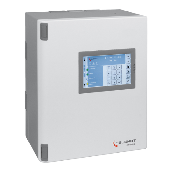
- Page 1 INTRUDER ALARM CONTROL PANEL complex 200H complex 400H BT 820/830/840/800 USER MANUAL Version (09) english...
-
Page 2: User Notes
User notes User notes Before using the product, read the user manual carefully and keep it for future reference. Do not open the product. All installation and main- tenance work may only be carried out by an expert installer. The user manual describes an intruder alarm control pa- nel that is installed in accordance with VdS guidelines. -
Page 3: Table Of Contents
Table of content Table of content User notes 5.4.3 Walk test ......26 Table of content 5.4.4 Disable input group . -
Page 4: Table Of Content
Table of content Operation with switching lock ....43 6.4.1 Shunt lock ......43 6.4.2 Pulse switching lock . -
Page 5: Terms
Terms, abbreviations, and symbols Terms, abbreviations, and symbols Shunt lock A switching device in the form of a lock that is integrated in the Terms door and can be used to set and unset the system. The shunt lock also prevents setting for as long as a setting prevention Alarm criterion is present (see Coerciveness). - Page 6 Terms, abbreviations, and symbols External alarm Transponder Alerting using an externally installed warning device (siren and An electronic key for operating an electronic switching device. strobe beacon) and/or the sending of a message to the response The transponder for actuation of the switching procedure is authorities.
- Page 7 Terms, abbreviations, and symbols Input group Tamper contact An input group combines multiple dedicated signals so that The intruder alarm system components' lids or parts of the they can be indicated or disabled together on the keypad, e.g. housings that can be opened are equipped with tamper contacts motion detectors if the system is internally set.
- Page 8 Terms, abbreviations, and symbols Silent alarm Lock state monitoring Alerting which involves sending a message to the response The locks on all access doors to partitions are fitted with bolt authorities without activating an internal/external alarm. This contacts that monitor the lock state of the doors. It ensures the alarm is used for hold-ups.
-
Page 9: Terms, Abbreviations, And Symbols
Terms, abbreviations, and symbols Abbreviations Symbols General Important notice, order = Keypad Tips, recommendations, useful information IACP = Intruder alarm control panel = Transmission device Usage not in compliance with VdS directives Partition status Legend = External alarm Sequence of action = External exit time = Externally set Switching device... -
Page 10: Basics Of The Intruder Alarm System Structure
Basics of the intruder alarm system Basics of the intruder alarm system The TD (transmission device) transmits alarm, state, and fault messages to a response authority, e.g. surveillance and secu- Structure rity service. The TD uses the telecommunications network for transmission. -
Page 11: Partitions
Basics of the intruder alarm system Partitions Setting states 4 3 1 Externally set An intruder alarm system can include several partitions. These partitions can be set or unset either in a mutually dependent The system is set with no persons inside the partition(s). manner or completely independently of one another. -
Page 12: Internally Set
Basics of the intruder alarm system 4 3 2 Internally set 4 3 3 Unset The system is set with persons present in the The system is not set. partition(s). While the system is unset, some functions of the intruder alarm The keypad or an internal switching device is used for internal control panel will still be active. -
Page 13: Alarm Status And Resetting
Basics of the intruder alarm system Detector Coerciveness If a tamper alarm, an intruder alarm, or a fault is pending, To ensure that the IACP can detect and report different hazar- the system cannot be set (coerciveness). Lock state moni- dous situations, a variety of detector types must be installed toring also affects the coerciveness, i. e., if a detector is not in the system. - Page 14 Basics of the intruder alarm system The housings on all components are fitted with Detector Reaction of system tamper contacts or similar protective mechanisms, Unset Internally set Externally set which activate a tamper alarm in response to a mechanical attack on the components. Magnetic contact on Only displayed Internal alarm External alarm...
-
Page 15: Keypad
BT 800/801: TELENOT offers a variety of keypads for operating the IACP. For information, refer to the TELENOT website at www.telenot.com. The operating procedure for the IACP using the example of the M o 1 5 . - Page 16 Keypad Switching of the screen pages Icons One screen page back "Switching Functions" screen page "Overview" screen page Icons "Keypad" screen page Icons Color Function "Indication Panel 1" screen page Alarm Blinks for triggered and saved alarms "Indication Panel 2" screen page Fault Yellow Blinks for pending and saved faults One screen page forward...
- Page 17 Keypad Display indication Freely parameterizable LEDs 1–4 Ready to be M o 2 0 . 0 1 . 1 4 externally set 1 2 : 1 9 Unset Display indication Internally set The display has a limited number of characters. Long Alarm texts are divided in two indications, which are displayed alternatingly.
- Page 18 Keypad Operating buttons LED indication (operating states) Scroll back Scroll forward Unsetting Internal setting LED indication (operating states) External setting (only if enabled) LED indication Color Function Freely parameterizable button (operating states) Operation Green Illuminated during operation and blinks during initialization Alarm Illuminated by triggered and Operating buttons...
-
Page 19: Indication Panel 1/2" Screen Page
Keypad 5 1 2 "Indication panel 1/2" screen page LED “Input group state”: This LED (red) indicates whether at least one dedicated signal in this input group is open or in the alarm state. IG1 (Tamper) Input group 9 Input group text: The input group text is displayed here as Input group 2 Input group 10 defined in the IACP parameterization. -
Page 20: Overview" Screen Page
Keypad 5 1 3 "Overview" screen page 5 1 4 "Switching Functions" screen page M o 1 5 . 0 5 . 1 7 Ready to be externally set 0 9 : 3 2 Unset M o 1 5 . 0 5 . 1 7 Internally set Alarm Door 1... -
Page 21: Settings Menu
Keypad 5 1 5 Settings menu Enter the access-enabling code (E3) and confirm your input with the “Enter” button. The access-enabling code From the settings menu, the following parameters can be (E3) that you need to use depends on the parameteriza- adjusted: tion. -
Page 22: Structure Of Bt 820
Keypad Structure of BT 820 LED indication Color Function (operating states) Operation Green Illuminated during operation and blinks during initialization Display Alarm Illuminated by triggered and Labeling fields saved alarms Operation Alarm Fault Yellow Illuminated by pending and Scroll up / down Fault saved faults Walk test... - Page 23 Keypad Menu item Function Access level with code Access level without code (Code X) (Code Y) (Code Z) Indication test? Testing all LEDs and the buzzer on the keypad Walk test ? Switching the walk test for motion detectors on/off Disable IG? Disabling/enabling input groups OverrideSetting? Switching off triggered detectors that are not in quiescent mode for one setting (not in compliance with...
-
Page 24: Menu Structure
Keypad Menu structure The keypad only displays the menu items that are available on Press the "Menu" button. the respective access level. Indication test? Navigate through the menu using the "Scroll" buttons. Due to the use of abbreviations in the representation and the Walk test ? large number of selection options, the display indications of Press "Enter"... -
Page 25: Alarm Memory
Keypad 5 4 1 Alarm memory The alarm memory contains the following information: Status of the partitions Pending alarms Mo 15.05.17 Pending faults 09:32 Pending warnings The corresponding Open dedicated signals status is shown in Access enabling! Code: ###### abbreviated form 5 4 2 Indication test under the number... -
Page 26: Walk Test
Keypad 5 4 3 Walk test 5 4 4 Disable input group (Access level: L1, L2 and L3) (Access level: L2 and L3) Walk test ? Walk test: Disable IG? Office < enabled < Walk test: Office < disabled ( IU) < Menu item "Walk test"... -
Page 27: Override Setting
Keypad 5 4 5 Override setting The override setting makes it possible to set the intruder alarm system internally or externally despite the setting prevention (Access level: L2 and L3) (not in compliance with VdS). To do this, the installer must ena- ble the dedicated signals for this process when parameterizing the intruder alarm system and must specify the type of setting (E = externally set, I = internally set and U = unset) for which the... -
Page 28: Changing The Keypad Code
Keypad 5 4 6 Changing the keypad code 5 4 7 Reset tamper (Access level: L2 and L3) (Access level: L2 and L3) Cl. B/C Change KP-Code ? to be changed Reset Tamper ? Reset Code: ###### activated Autom. return to menu Cl. -
Page 29: Versions
Keypad 5 4 8 Versions 5 4 9 Event memory (Access level: L2 and L3) (Access level: L3) Event memory ? 0000 07h59 08.06 Versions ? EMZ complex 400 disabled garage Version: 24.55 Joe Bloggs 1 comlock reader 1 UE:comXline 2516 Version: 12.42 0001 05h20 06.08 alarm... -
Page 30: Alarm Counter
Keypad 5 4 10 Alarm counter 5 4 11 Disabling of keypad code (Access level: L3) (Access level: L3) Alarm counter ? No. of alarms: Disable KP-Code? Joe Bloggs 1 00132 enabled < Joe Bloggs 1 disabled < Menu item "Alarm counter" Joe Bloggs 2 The alarm counter counts the alarms that have occurred in the enabled... -
Page 31: Disable Comlock/Cryplock Code
Keypad 5 4 12 Disable comlock/cryplock code 5 4 13 comlock/cryplock identification (Access level: L3) (Access level: L3) CL-Ident. ? Text: (owner) Disable CL-Code? Joe Bloggs 1 Joe Bloggs 1 enabled < Joe Bloggs 1 disabled < Menu item "comlock/cryplock identification" Joe Bloggs 2 During comlock/cryplock identification, you can identify a (e.g. -
Page 32: Service Enabling
Keypad 5 4 14 Service enabling 5 4 15 App enabling (Access level: L3) (Access level: L3) Service release? Service release: App-Enable? App-Enable: disabled < permanently < Service release: App-Enable: Time limit 1h < up to ext. set < Service release: disabled <... -
Page 33: Operation With Keypad
Keypad Operation with keypad 5 5 1 External setting Mo 15.05.17 Due to the use of abbreviations in the representation and the Standard indication 09:32 large number of selection options, the display indications of the complex 400H will be used in the further graphics. Press the "External setting"... -
Page 34: Internal Setting
Keypad 5 5 2 Internal setting 5 5 3 Unsetting Mo 15.05.17 Mo 15.05.17 Standard indication Standard indication 09:32 09:32 Press the "Internal setting" button. Press the "Unset" button. int. setting: Enter the access-enabling code and confirm your unsetting Enter the access-enabling code and confirm your Code: ###### input with the "Enter"... -
Page 35: External Setting With Delayed Area Function
Keypad 5 5 4 External setting with delayed area function 5 5 5 Unsetting with delayed area function During the exit time, only the detectors associated with During the entry time, only the detectors associated the delayed area are delayed. All other detectors trigger with the delayed area are delayed. -
Page 36: Resetting Alarms, Faults, And Battery Warnings
Keypad 5 5 6 Resetting alarms, faults, and battery warnings Mo 15.05.17 Standard indication 09:32 You can only reset alarms, faults, and warnings that are Press any button. permitted for the respective keypad and respective au- thorization level. Tamper alarms up to VdS class A must Access enabling! Enter the access-enabling code and confirm your input with the "Enter"... -
Page 37: Switching Device
Switching device Switching device Structure of the reader comlock R-ED The reader cryplock R-ED is fitted with a numeric pad, a trans- A responsible operator can use a reader to set/unset the system. ponder zone, a three-color LED, and a built-in buzzer. The reader is operated with a transponder, entry of a numeric- pad code or a combination of both variants. -
Page 38: Operation With Reader
Switching device Operation with reader Hold the transponder (approx. 3 s) in front of the reader (transponder zone). The maximum clearance is 10 mm. 6 3 1 External setting Confirmation: Single beep from the buzzer (approx. 0.25 s) and brief illumination of the yellow LED (approx. 0.25 s). External setting with transponder This is followed by: Double beep from the buzzer (2 × ap- prox. 0.15 s) and double illumination of the yellow LED... - Page 39 Switching device External setting with numeric-pad code Enter the numeric-pad code. Every numerical input is confirmed with a beep from the buzzer (approx. 0.15 s) and brief illumination of the yellow LED (approx. 0.15 s). LED green If you make an incorrect entry, press the “Esc” button LED red and enter the numeric-pad code again LED yellow...
-
Page 40: Unsetting
Switching device 6 3 2 Unsetting Hold the transponder briefly (approx. 1 s) in front of the reader (transponder zone). The maximum clearance is Unsetting with transponder 10 mm. Confirmation: Single beep from the buzzer (ap- prox. 0.25 s) and brief illumination of the yellow LED LED green (approx. 0.25 s). - Page 41 Switching device Unsetting with numeric-pad code Enter the numeric-pad code. Every numerical input is confirmed with a beep from the buzzer (approx. 0.15 s) and brief illumination of the yellow LED (approx. 0.15 s). LED green If you make an incorrect entry, press the “Esc” button LED red and enter the numeric-pad code again LED yellow...
-
Page 42: Change Numeric-Pad Code With Change Code
Switching device 6 3 3 Change numeric-pad code with change code Enter the new numeric-pad code again. Notice: You have 5 s to enter the code, otherwise the On a numeric-pad reader, you can use the change code to process is canceled change the parameterized numeic-pad code. -
Page 43: Operation With Switching Lock
Switching device Operation with switching lock 6 4 2 Pulse switching lock 6 4 1 Shunt lock External setting Insert the key into the lock and turn it to the right. External setting Lock the door lock. Externally set The intruder alarm system is externally set. Lock the shunt lock. -
Page 44: System Does Not Set What Can I Do
System does not set What can I do? System does not set What can I do? The setting prevention is indicated by intermittent Display beeping of the buzzer (alternating: approx. 0.25 s tone / approx. 0.25 s pause) for 10 s. LED "Operation" For external setting: The "Operation" LED and the "Ready Operation LED "Alarm"... - Page 45 System does not set What can I do? LED indication (operating states) Cause What to do? LED "Operation" is not illuminated The system is already exter- nally set LED "Alarm" is illuminated An alarm is not yet reset Read the message memory to determine the alarm in question. If there is no longer any danger, reset the alarm (see Keypad / Operation with keypad / Resetting alarms, faults and battery warnings).
-
Page 46: Maintenance And Care
Maintenance and care In compliance with VdS class C, three inspections (VdS Maintenance and care class B: two inspections) and one maintenance of the sys- Since the IACP is operated in clean indoor rooms, there is tem and system part must be carried out annually by the generally no need for cleaning. -
Page 47: Behavior In Case Of An Alarm
Behavior in case of an alarm Behavior in case of an alarm Alarm (when internally set) Alarm (when externally set) Non self-triggered alarm Remain calm. Non self-triggered alarm Remain calm. For intruder alarm systems with an internal alarm without remote alerting: Assess the situation and call For intruder alarm systems with an external alarm for assistance. - Page 48 Subject to technical modifications...
Need help?
Do you have a question about the complex 200H BT 820 and is the answer not in the manual?
Questions and answers