Advertisement
Available languages
Available languages
Quick Links
Quick Start Guide
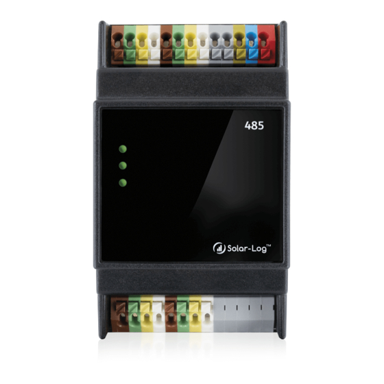
Solar-Log MOD 485
Introduction
This quick start guide is intended for use by solar energy technicians, professional electri-
cians, and Solar-Log Base users. Installation and commissioning of the individual components
should only be performed by properly trained specialists. Be sure to fully read and understand
all instructions in this manual before installing, operating and/or servicing the device.
Please observe!
Disconnect the power of the Solar-Log Base before plugging in/out the bus
connector and before connecting the module with the Solar-Log™.
Assembly
The Solar-Log module MOD 485 is manufactured according to protection class IP20 and
is only suitable for installation in dry, dust-free indoor areas. The assembly itself can be carried
out both via wall mounting as well as on a DIN rail. Power is supplied via the bus system by the
Solar-Log Base.
Module Solar-Log MOD 485 connection and mounting
Take one of the 2 bus connectors included in the scope of delivery. The bus connector is
plugged into the back of the Solar-Log Base.
Take the second bus connector and plug it into the back of the Solar-Log MOD 485.
To complete the HBus connection, plug the two bus connectors together.
Now the connected housings can be snapped into the DIN rail.
Follow the short instructions Solar-Log Base.
Can only be used with Solar-Log Base firmware 6.x or higher.
Connections
Top
RS485 B
RS485 A
W.f.*
Power
13 12 11 10 9
8
7
6
5
4
3
2
1
RS422
*Without function
Bottom
RS485 D
RS485 C
Without function
8
7
6
5
4
3
2
1
RS422
Top/bottom side each 2 x RS485 or 1 x RS422
Use the provided terminal blocks when connecting inverters or accessories to the RS485 or
RS422 interface.
Note when using the RS422 interface
If inverters are connected to this RS422 interface (e.g. Fronius, AEG, Riello), then it is not
possible to connect accessories such as sensors or meters to this bus.
Pin/Top
RS485-A/B
RS422
1
-
-
2
-
-
3
-
-
4
-
-
5
-
-
6
Data +
T/RX+
7
24 V / (12 V)
24 V / (12 V)
8
Ground / GND Ground / GND -
9
Data -
T/RX-
10
Data +
R/TX+
11
24 V / (12 V)
-
12
Ground / GND -
13
Data -
R/TX-
Pin/Bottom
RS485-C/D
RS422
1
Data +
T/RX+
2
24 V / (12 V)
24 V / (12 V)
3
Ground / GND Ground / GND
4
Data -
T/RX-
5
Data +
R/TX+
6
24 V / (12 V)
-
7
Ground / GND -
8
Data -
R/TX-
Technical Data
Device voltage
24V (+-5 %), in exceptional cases 12V (+-5 %)
Solid conductor: 0.2 ... 1.5 mm² / 24 ... 16 AWG
Fine-stranded conductor: 0.2 ... 1.5 mm² / 24 ... 16 AWG
Cable cross-section
With ferrules: 0.14 - 1 mm² (ferrules – to be
used for fine-stranded conductor)
Strip length
8.5 ... 9.5 mm / 0.33 ... 0.37 inch; with ferrules
Power consumption
2.4W
Voltage of the control signal corresponds to
Control signal
Supply voltage of the Solar-Log Base
Dimensions (WxHxD) in mm
53,6 x 89,7 x 60,3
Solar-Log GmbH • www.solar-log.com • Subject to change without notice. EN | 04.2022 | Version 1.0| Art.Nr.: 15557
Power
Vin 24VDC / (12 VDC)
GND
FE
-
-
-
-
-
-
-
-
-
≧
6 mm / 0,24 inch
Advertisement

Summary of Contents for Solar-Log MOD 485
- Page 1 Voltage of the control signal corresponds to Control signal *Without function Supply voltage of the Solar-Log Base Dimensions (WxHxD) in mm 53,6 x 89,7 x 60,3 Solar-Log GmbH • www.solar-log.com • Subject to change without notice. EN | 04.2022 | Version 1.0| Art.Nr.: 15557...
- Page 2 Rückseite des Solar-Log Base eingesteckt. Nehmen Sie den zweiten Busver- Data + T/RX+ binder und stecken diesen auf der Rückseite des Solar-Log MOD 485 ein. Um die HBus 24 V / (12 V) 24 V / (12 V) Verbindung fertigzustellen, stecken Sie die beiden Busverbinder zusammen.
Need help?
Do you have a question about the MOD 485 and is the answer not in the manual?
Questions and answers