Table of Contents
Advertisement
Quick Links
SIP Industrial Products Limited
Gelders Hall Road
Shepshed
Loughborough
Leicestershire
LE12 9NH
United Kingdom
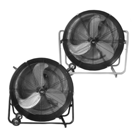
30" Drum Fans
SIP Code: 05639, 05640
For help or advice please contact
your distributor, or sip directly
Instruction Manual
on:
Tel.: 01509 500400
Email:
sales@sip-group.com
or
customerservice@sip-group.com
Please read and fully understand the instructions in this manual before operation. Keep
this manual safe for future reference.
www.sip-group.com
Advertisement
Table of Contents

Related Manuals for SIP 05639


Summary of Contents for SIP 05639
- Page 1 SIP Industrial Products Limited Gelders Hall Road Shepshed Loughborough Leicestershire LE12 9NH United Kingdom 30” Drum Fans SIP Code: 05639, 05640 For help or advice please contact your distributor, or sip directly Instruction Manual Tel.: 01509 500400 Email: sales@sip-group.com customerservice@sip-group.com Please read and fully understand the instructions in this manual before operation.
-
Page 2: Table Of Contents
Electrical Connection 5 - 6 Technical Specification Warranty Contents & Accessories Getting To Know Your Drum Fan - 05639 Getting To Know Your Drum Fan - 05640 Operating Instructions Wiring Diagram - 05639 Wiring Diagram - 05640 Exploded Drawing / Parts List - 05639 Exploded Drawing / Parts List - 05640 UK &... -
Page 3: Safety Symbols Used Throughout This Manual
SAFETY SYMBOLS USED THROUGHOUT THIS MANUAL Danger / Caution: Indicates risk of personal injury and/or the possibility of damage. Warning: Risk of electrical injury or damage! Note: Supplementary Information. SAFETY INSTRUCTIONS Important: Please read the following instructions carefully, failure to do so could lead to serious personal injury and / or damage to the drum fan. - Page 4 SAFETY INSTRUCTIONS….Cont lead is damaged it must be replaced by the manufacturer or its service agent or a similarly qualified person in order to avoid unwanted hazards. HAVE YOUR FAN REPAIRED BY A QUALIFIED PERSON: The fan is in accordance with the relevant safety require- ments.
-
Page 5: Electrical Connection
SAFETY INSTRUCTIONS….Cont • Never insert fingers or any other object/s through the grill guard when the fan is in operation. • Never leave the fan unattended and ensure that children and pets are kept a safe distance from the fan. •... - Page 6 Connecting to the power supply: These SIP drum fans are fitted with either a standard 230v ~ 13 amp or 110v ~ 16 amp type plug. Before using the drum fan, inspect the mains lead and plug to ensure that neither are damaged. If any damage is visible have the drum fan inspected / repaired by a suitably qualified person.
-
Page 7: Technical Specification
TECHNICAL SPECIFICATION Item No. 05639 05640 Supply 220-240V~ 50Hz 110V~ 50Hz No. of Speed Settings Power Consumption (W) - Low 109W 111W Power Consumption (W) - High 123W 123W Input Current (A) - Low 0.48A 1.04A Input Current (A) - High 0.53A... -
Page 8: Warranty
WARRANTY These SIP drum fans are covered by a 12 month parts and labour warranty covering failure due to manufacturers defects. This does not cover failure due to misuse or operating the fan outside the scope of this manual - any claims deemed to be outside the scope of the warranty may be subject to charges Including, but not limited to parts, labour and carriage costs. -
Page 9: Getting To Know Your Drum Fan - 05639
GETTING TO KNOW YOUR DRUM FAN - 05639 Front Rear Item Description Item Description Speed Control Knob Frame Motor Foot Handle Wheels Drum Body Fan Blade... -
Page 10: Getting To Know Your Drum Fan - 05640
GETTING TO KNOW YOUR DRUM FAN - 05640 Front Rear Item Description Item Description Speed Control Knob Foot Motor Wheels Drum Body Fan Blade Frame Power Cord... -
Page 11: Operating Instructions
OPERATING INSTRUCTIONS Note: Always allow at least 1 metre clearance around the fan, failure to adhere to this will stop the cooling air flowing through the drum fan, this could damage the motor and void your war- ranty. The drum fan has 2 different speed settings: 0 --- Stop 1 --- Low 2 --- High... -
Page 12: Wiring Diagram - 05639
WIRING DIAGRAM - 05639... -
Page 13: Wiring Diagram - 05640
WIRING DIAGRAM - 05640... -
Page 14: Exploded Drawing / Parts List - 05639
EXPLODED DRAWING / PARTS LIST - 05639 Item Description Item Description Front Guard Switch Box Blade Component Switch Knob Handle Capacitor Drum Power Cord Rear Guard Triangle Knob Motor Bracket Switch Wheels... -
Page 15: Exploded Drawing / Parts List - 05640
EXPLODED DRAWING / PARTS LIST - 05640 Item Description Item Description Front Guard Switch Knob Blade Component Capacitor Drum Power Cord Rear Guard Plum Knob Motor Bracket Switch Wheels Switch Box... -
Page 16: Eu - Declaration Of Conformity
England As the manufacturer within England, Scotland and Wales, we de- clare that the 30” Drum Fans - SIP Part No. 05639 & 05640 Conforms to the requirements of the following regulation(s), as indicated. Electrical Equipment (Safety) Regulations 2016 Electromagnetic Compatibility Regulations 2016... - Page 17 Dundalk County Louth As the manufacturer's authorised representative within the EC de- clare that the 30” Drum Fans - SIP Part No. 05639 & 05640 Conforms to the requirements of the following directive(s), as indicated. 2014/35/EU Low Voltage Directive 2014/30/EU EMC Directive 2015/863/EU &2011/65/EU...
-
Page 18: Notes
NOTES... - Page 19 NOTES...
- Page 20 This will allow the recycling of raw materials and help protect the en vironment. FOR HELP OR ADVICE ON THIS PRODUCT PLEASE CONTACT YOUR DISTRIBUTOR, OR SIP DIRECTLY TEL: 01509 500400 EMAIL: sales@sip-group.com or technical@sip-group.com www.sip-group.com...
Need help?
Do you have a question about the 05639 and is the answer not in the manual?
Questions and answers