
Subscribe to Our Youtube Channel
Related Manuals for ECM AFM1000


Summary of Contents for ECM AFM1000
- Page 1 ™ ™ AFM1000 / AFM1500 Air-Fuel Ratio Combustion Monitor Extended Range (6 ~ 20 AFR) Version Instruction Manual 02/06 Part Number 1000A-6b...
- Page 2 No part of this manual may be photocopied or reproduced in any form without prior written consent from ECM: ENGINE CONTROL AND MONITORING. Information and specifications subject to change without notice. AFM1000 and AFM1500 are trademarks of ECM: Engine Control and Monitoring. Printed in the United States of America.
-
Page 3: Table Of Contents
Table of Contents Introduction The Air-Fuel Ratio Combustion Monitor (AFM) AFM1000/AFM1500 Components List Important Operation Notes How to Use Hooking-up the AFM Power Warm-up Analog Output SMB Interface (Serial Measurement Bus, AFM1500 Only) Calibration Fuel Type Compensation Pressure Compensation Specifications and Limits... - Page 4 Supplementary Information...
-
Page 5: Introduction
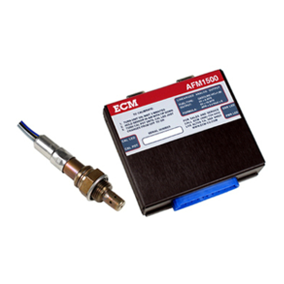
Introduction The Air-Fuel Ratio Combustion Monitor (AFM1000/AFM1500) The ECM Air-Fuel Ratio Combustion Monitor (AFM) was designed for the professional calibration of fuel-injection or carburetor systems. Using a state-of-the-art, wide-range UEGO (Universal Exhaust Gas Oxygen) sensor, the AFM provides unmatched measurement range, accuracy, and speed-of-response in a compact, lightweight package. - Page 6 Wiring Harness, 10’ or 1002A-3b Wiring Harness, 3’ 1002A-3c SMB/PC Cable, 6' (AFM1500) 1500A-16 SMB/PWR Cable, 1' (AFM1500) 1500A-17 Calibration Screwdriver 2400E-35 Sensor Mounting Boss and Plug (M18X1.5mm) 1000A-5 Instruction Manual 1000A-6b ECM offers custom harness solutions. Contact ECM for more information.
-
Page 7: Important Operation Notes
Important Operation Notes 1. Before installing the UEGO sensor, apply a small amount of non-lead containing antiseize compound to its threads. Do not get the compound on the sensor’s tip. 2. Do not operate an engine for more than three minutes with the UEGO sensor in the exhaust and the control module’s power off. -
Page 8: How To Use
How to Use Hooking-up the AFM Location of the UEGO Sensor The UEGO sensor should be located from 12" to 48” from the exhaust valve(s) of the engine. A location further from the engine may be used as long as it is at least ten times the exhaust pipe diameter upstream of the end of the exhaust system. -
Page 9: Power
The AFM has a 0V to 5V linearized output suitable for input into a data acquisition or engine control system. The analog output is available from the female BNC connector on the wiring harness. For the AFM1000 only, the shell of the connector is signal ground and it is electrically connected to the power source ground. -
Page 10: Smb Interface (Serial Measurement Bus, Afm1500 Only)
SMB Interface (Serial Measurement Bus, AFM1500 Only) The AFM1500 has a SMB interface allowing serial communication with as many as 16 AFM1500 modules using a single RS-232 type serial port from a computer. Using the SMB interface, AFR, FAR (the inverse of AFR), Lambda, %O , and module status can be read from each AFM1500 module. - Page 11 COMMAND DESCRIPTION RANGE FORMULA See Command Mode and Device Enter Command Mode Identification Sections 8 bit λ 0.744 to 1.373 λ = (Data Byte + 186)/250 16 bit λ High Byte 0.412 to 1.373 λ = (High Byte*256 + Low Byte)/1000 16 bit λ...
-
Page 12: Calibration
Command Mode Command Mode is used to auto-detect AFM1500 and F/A1000 modules on the SMB bus. After the reception of command XXXX 0000 (where XXXX = module address) the module switches into Command Mode and waits for a second byte. Upon entering Command Mode, wait 30 ms minimum before issuing commands. -
Page 13: Fuel Type Compensation
Fuel Type Compensation The standard AFM output is for gasoline (measurement range of 6.0 to 20.0 AFR) with a fuel H:C ratio of 1.85 and an O:C ratio of zero. If a fuel of a different composition is used, the AFR measurement range will be different. - Page 14 Pressure Compensation Equation for AFR [Equation 3a] AFR(corrected) = (AFR(measured) + B x P) / (1 + C x P) where: AFR(corrected) = the AFR corrected for exhaust pressure. AFR(measured) = the AFR output by the AFM. B = 0.009140 for AFR < 14.57 (rich). B = 0.012100 for AFR ≥...
-
Page 15: Specifications And Limits
Specifications and Limits Measurement Range and Accuracy Range: 6 to 20 AFR (gasoline) (Analog Output and SMB) 0.050 to 0.167 FAR, 0.412 to 1.37 Lambda, 0.0 to 5.46 %O (SMB Only) Accuracy: 1.5% Exhaust Operating Limits Maximum Exhaust Gas Temperature: 950 deg. C, 1742 deg. F. Exhaust Gas Pressure Range: 0.8 - 1.7 atm (gauge). -
Page 16: General Information
SMB Interface (Serial Measurement Bus, AFM1500 Only): • AFR, FAR, Lambda, %O2, and Module Status Output • Each Module can be assigned an address from 0h to Fh using a switch on the side of the module • Auto-detect feature for Device Identification •... -
Page 17: Troubleshooting
2. For the AFM1000 only, the ground wire on the wiring harness is not attached directly to the ground at the vehicle's battery. If you connect a single wire from... -
Page 18: Safety Warnings
Safety Warnings In the installation and use of this product, comply with the National Electrical Code and any other applicable Federal, State, or local safety codes. Always wear eye protection when working near engines, vehicles, or machinery. During installation, turn off the power and the engine and take all other necessary precautions to prevent injury, property loss, and equipment damage. -
Page 19: Warranty And Disclaimers
Warranty and Disclaimers WARRANTY The products described in this manual, with the exception of the UEGO sensor, are warranted to be free from defects in material and workmanship for a period of one year from the date of shipment to the buyer. Within the one year warranty period, we shall at our option replace such items or reimburse the customer the original price of such items which are returned to us with shipping charges prepaid and which are determined by us to be defective. - Page 25 State Diagram for SMB Communication...
- Page 28 Los Altos, CA 94023-0040 • USA • (408) 734-3433 • Fax: (408) 734-3432 www.ecm-co.com...
Need help?
Do you have a question about the AFM1000 and is the answer not in the manual?
Questions and answers