Table of Contents
Advertisement
Quick Links
TMG-TBH90
PRODUCT MANUAL
v2023.01.13
9 FT TRACTOR
SWING BACKHOE ATTACHMENT
Please read and understand the product manual completely before assembly
Check against the parts list to make sure all parts are received
Wear proper safety goggles or other protective gears while in assembly
Do not return the product to dealer. They are not equipped to handle your requests.
Missing parts or questions on assembly?
Please call: 1-877-761-2819 or email: cs@tmgindustrial.com
Advertisement
Table of Contents

Summary of Contents for TMG TMG-TBH90
- Page 1 TMG-TBH90 PRODUCT MANUAL v2023.01.13 9 FT TRACTOR SWING BACKHOE ATTACHMENT Please read and understand the product manual completely before assembly Check against the parts list to make sure all parts are received Wear proper safety goggles or other protective gears while in assembly Do not return the product to dealer.
-
Page 2: Table Of Contents
TABLE OF CONTENTS IMPORTANT SAFETY INFORMATION ......................3 SAFETY DECAL LOCATIONS ......................... 8 PARTS DESCRIPTION AND FUCTION ......................10 PRODUCTS SPECIFICATIONS ........................11 UNPACKING & ASSEMBLY ........................... 12 CONNECTING TRACTOR ..........................23 CHECK BEFORE OPERATING ........................24 CHECK BEFORE OPERATING ........................20 LUBRICATION POINTS SUMMARY ...................... -
Page 3: Important Safety Information
IMPORTANT SAFETY INFORMATION Before operating the BACKHOE read the following safety instructions. Failure to comply with these warnings may result in serious injury or death. Safety Instructions The alert symbol is used throughout this manual and this manual and on the product safety decals. This symbol indicates attention is required and identifies hazards concerning your personal safety and the safety of others. - Page 4 Safety Rules It is the operator's responsibility to read, understand and follow ALL safety and operation instructions in this manual. If you do not understand any part of this manual and require assistance, contact your dealer. The operator of this backhoe must be a responsible, physically able person familiar with machinery and trained in this machine's operation.
- Page 5 • Be sure machine is properly mounted, adjusted and in good operating condition. • Follow the Pre-operation Checklist before starting work. • If the backhoe is powered by the tractor / skid steer hydraulic system, oil pressure and flow must be properly matched. If a PTO drive is used, be sure speed is correct and PTO shaft is properly shielded.
- Page 6 Maintenance Safety • Have at least two workers present when performing maintenance on this equipment. Never work alone in case an emergency should arise. • Keep service area clean and dry. • Never operate the engine in a closed building. Make sure there is plenty of ventilation. Exhaust fumes can cause asphyxiation.
- Page 7 Work Zone Establish a Work Zone perimeter the length of maximum boom reach and swing arc. Mark an additional area at least 3 ft (1 m) around the stabilizers. While using the backhoe, always be aware of bystanders in the area. A swinging boom can create a collision hazard to workers or bystanders.
-
Page 8: Safety Decal Locations
SAFETY DECAL LOCATIONS The safety decals and their positions are shown on the illustration below. Good safety requires that you familiarize yourself with the various safety decals, the type of warning and the area or specific function related to that area that requires your SAFETY AWARENESS. - Page 9 Warning Decals...
-
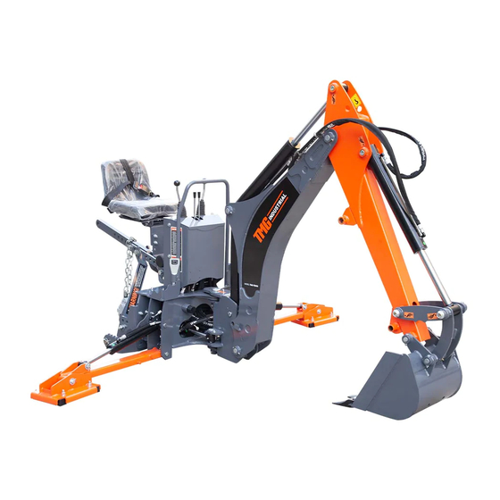
Page 10: Parts Description And Fuction
PARTS DESCRIPTION AND FUCTION 1. Console assembly 2. Boom assembly 3.Seat assembly 4.Three-point hitch assembly 8. Bucket assembly 7. Outrigger assembly 6.Base assembly 5. Steering assembly 1.Console assembly: Control machine 2.Boom assembly: The arm that performs the digging action 3.Seat assembly: Sit on the seat when operating the machine 4.Three-point hitch assembly: Connecting Tractor and Backhoe... -
Page 11: Products Specifications
PRODUCTS SPECIFICATIONS Specifications TMG-BH900 Digging Depth(2 ft. flat bottom) 9’ Overall Operating Height(fully raised) 123” Reach from Swing POST 129” Loading Height(bucket at 60°rotation) 84” Dipper Boom Digging Force 2200 lbs Transport Height(with boom fully retracted) 80” Transport Width(with stabilizers up) 58”... -
Page 12: Unpacking & Assembly
UNPACKING & ASSEMBLY 1. After unpacking, check the following components (Optional) The parts marked with numbers in the figure are the parts that need to be assembled. *. All numbers are not part numbers in the drawings. For correct part numbers, see explosive diagram. - Page 13 DESCRIPTION DESCRIPTION Base assembly Cotter pin 4x32 Small boom assembly Pin shaft Ø30x181 Seat components Pin shaft Ø25x137 Upper link assembly Fully threaded hex bolts M6x50 Tie rod welding Fully threaded hex bolts M6x60 Three-point suspension Non-metallic insert hex lock nuts connection seat welding Stabilizer legs assembly Pin welding 142...
- Page 14 2. Install the Stabilizer Legs Assembly Installation steps: Place the stabilizer legs assembly (5) at the position shown in the figure above, align it with the installation hole on the base assembly (1), pass through the pin shaft Ø20x133 (A14), and install the washer 20 (A13), and the cotter pin 4x32 (A12) , the left and right outriggers are installed in the same way.
- Page 15 3. Install three-point hitch assembly...
- Page 16 Installation steps: 1. Align the assembly of upper link (G1) with the mounting hole under the seat, insert it into hexagon head bolt (G19), plain washer (G5), and then secure it with plain washer (G5) and locknut (G6), taking care to tighten the bolts after all components are installed.
- Page 17 4. Install the seat assembly A6-A7-A8 Installation steps: Align the seat assembly (1) with the 4 mounting holes on the the base assembly, and install the full-threaded hexagon bolt (A6), plain washer (A7), non-metallic insert hexagon lock nut (A8), taking care to tighten the bolts after all components are installed. Importance: All bolts are locked in place without shaking.
- Page 18 5. Install small boom assembly Installation steps: 1. Align the small boom assembly (D13) with the mounting hole on the base assembly as shown in the above figure, penetrate the pin shaft Ø30x181 (D9), install the bolt M6×60 (D8), and the nut M6 (D3) to lock and fix it. 2.
- Page 19 6. Install and connection hydraulic tubing...
-
Page 20: Check Before Operating
Connection steps: As shown in the figure above, there are still 6 oil pipes that need to be connected. One side of these 6 oil pipes has been connected to the multi-way valve, and the other side needs to be connected to the oil cylinder. The product number is marked on the oil pipe joint. - Page 21 7. Install the gear pump assembly(Optional) 1. Remove the flow control valve assembly Remove Disassemble Disassemble Remove Disassemble Remove Remove steps: 1. Need to remove the flow control valve assembly installed on the machine first, loosen the 8 bolts on the two console covers, and remove the two console covers.
- Page 22 2. Install the gear pump assembly Locking Gear pump Hydraulic tank Locking Installation steps: 1. Connect the 4 bolts already installed on the oil tank assembly to the base of the machine and lock the bolts. 2. According to the corresponding letters in the figure, install the two tubing to the corresponding ports of the multi-way valve.. 3.
-
Page 23: Connecting Tractor
In the process of connection, when the tractor is the moving, if there is people between the tractor and working machine, it may cause injury accident. Be sure no people stand between the tractor and working machine during the tractor moving. Lower lifting pin types TMG-TBH90 CAT1 & CAT2 2. Connection and adjustment CAUTION! Makesurethetractorisfixedintheprocessofconnection. -
Page 24: Check Before Operating
CHECK BEFORE OPERATING 1. Check before operating Before operating the machine, check the following: 1. Check that the backhoe is properly attached to the power unit. Be sure retainers are used on the mounting pins and mounting hardware is tightened to their specified torque. 2. - Page 25 3. Remove swivel joint pin and pin welding 142 Keep the machine stable during transportation, so install limit pins for the base assembly and big boom assembly to hold. So you need to remove the limit pin on the arm and base before use 1.
- Page 26 4. Optional gear pump system connection Install the gear pump (H17)on the output shaft of the tractor, connect one end of the safety galvanized chains(H19) to the gear pump, and fix the other end to pull up bar (G1). If the gear pump cannot be mounted to the tractor output shaft, the user will need to purchase a conversion shaft...
-
Page 27: Lubrication Points Summary
LUBRICATION POINTS SUMMARY 4 lubrication points 4 lubrication points 9 lubrication points ● Designated parts have been oiling, please confirm beforeuse. -
Page 28: Controls
CONTROLS 1. Backhoe control Backhoe control configuration is SAE control mode. All controls are mounted on top of the base, when the operator sits When in the seat, it is easy to maneuver. All operators should read this section of the manual and be familiar with all the positions and functions of its controls before starting operation. - Page 29 4. Outrigger stabilizer, upward, downward • Push the second lever forward from the left to lower the left stabilizer. • Pull back the lever to raise the stabilizer. • Push the lever a second time forward from the right to lower the right stabilizer. •...
-
Page 30: Operating Essentials
OPERATING ESSENTIALS 1. Machine Set-up 1. Position the machine at the work site and set the park brake. 2. Set the stabilizers down to remove some of the weight from the tires. 3. On a tractor, lower the front bucket and set the stabilizers to remove some weight off the tires. Keep the tires in contact with the ground. - Page 31 3. Check the condition of the teeth on the bucket. Replace any that are bent, chipped, broken or missing. Check the oil level in the hydraulic reservoir if so equipped. 2Add as required. 5. Check the boom, dipper and bucket pivot pins. Be sure all are anchored securely in position. 6.
- Page 32 4. Excavating Always lower the stabilizers and front loader bucket. If the ground is soft, use pads or place wood blocking under the stabilizers. Do not undercut the stabilizers. Doing so could cause the stabilizer to give way and the backhoe could tip over into the excavation.
- Page 33 Lower stabilizers and front bucket before lifting a load 6. Digging with the Backhoe 1. Increase engine speed to mid-range or rated PTO rpm. 2. Engage hydraulic circuit or place hydraulic control in detent. If you have the optional PTO pump,engage PTO (refer to tractor manual).
- Page 34 7. Curl the bucket up when full. Raise the boom and at the same time, move the dipper out a little to keep soil from building up under the machine. Digging with Bucket 8. Swing away from your excavation and dump the bucket. Start dumping as the bucket approaches the pile. Do not waste time by dumping too far from the excavation.
-
Page 35: Operation Finish
OPERATING FINISH 1. Stopping and Parking the Machine Park the machine on dry, level ground. 1. Lower the boom to the ground. 2. Set the parking brake. 3. Allow the engine to idle for 5 minutes to cool. 4. Turn the hydraulic circuit OFF or disengage the PTO clutch (as equipped). 5. -
Page 36: Maintenance Schedule
MAINTENANCE SCHEDULE Perform maintenance procedures at time shown or hour interval, whichever comes first. Inspection unit list Inspection time Remove any entangled material from backhoe. Before/Post the job Check that all fasteners are tight. Before/Post the job Check the condition of all hydraulic lines, hoses, and fittings. Replace any that are damaged. -
Page 37: Troubleshooting
TROUBLESHOOTING PROBLEM PROBABLE CAUSE SOLUTION Oil filter plugged. Change filter. No pressurized hydraulic oil. Low hydraulic oil level. Add oil to reservoir. Pressure and return hoses to backhoe are Change hose connections. reversed. Cylinder rods do not Not enough oil flow. Flow control set too low. -
Page 38: Exploded View & Parts List
EXPLODED VIEW & PARTS LIST 1. Base and seat assembly PARTS LIST PART NO. DESCRIPTION PART NO. DESCRIPTION Base and seat assembly Stabilizer legs assembly Console assembly Bucket parts Boom rotation assembly Tractor 3-point hitch mount assembly Boom assembly Flow control valve assembly... - Page 39 2. Base and seat assembly PARTS LIST PART NO. DESCRIPTION PART NO. DESCRIPTION Seat Cotter pin 4x32 Seat bottom plate weldment Plain washers Ø20 Seat support plate weldment Outrigger cylinder pin Ø20x133 Large washer Base weldment Heptagon knob Ø40*M10*25 Buffer block Bushing C25×28×25 Fully threaded hex bolts M12×45 Steering cylinder upper bracket...
- Page 40 3. Console assembly PARTS LIST PART NO. DESCRIPTION PART NO. DESCRIPTION Console base welding Curved handle M12X235 Italian valve straight handle M8X210 Fully threaded hex bolts M8×16 Large washer Hex nuts M8 Standard spring washers Six-way multi-way valve Transition joint 12UNF3/4 Fully threaded hex bolts M8×30 Transition joint 08UNF3/4 Fully threaded hex bolts M10×30...
- Page 41 4. Boom rotation assembly PARTS LIST PART NO. DESCRIPTION PART NO. DESCRIPTION Combination washer Spacer Steering tee oil pipe Suspension pin Hollow bolt G1/4 Non-metallic insert hex lock nuts M8 Hollow bolt (extended) G1/4 Fully threaded hex bolts M8X70 Steering right cylinder oil pipe Bushing C30x34x30 Steering cylinder Steering welding...
- Page 42 5. Boom assembly...
- Page 43 PARTS LIST PART NO. DESCRIPTION PART NO. DESCRIPTION Straight-through pressure oil cup M8 Fully threaded hex bolts M8×50 Pin 165 Bushing C25×28×25 Non-metallic insert hex lock nuts M6 Fully threaded hex bolts M8x55 Hex head bolts M6x55 Bucket fixing pin Ø25x202 Boom oil cylinder inlet pipe Connecting rod weldment Boom cylinder oil outlet pipe...
- Page 44 6. Stabilizer legs assembly PARTS LIST PART NO. DESCRIPTION PART NO. DESCRIPTION Right outrigger cylinder oil inlet pipe Bottom plate weldment Outrigger cylinder Strut fixing pin Ø20x123 Outrigger cylinder oil outlet pipe Spring pin 5×30 Straight-through pressure oil cup M8 Hex nuts M12 Strut weldment Standard spring washers Ø12...
- Page 45 7. Bucket and thumb parts PARTS LIST PART NO. DESCRIPTION PART NO. DESCRIPTION Hexagonal bolt(fine pitch) M12x45 Hexagon nut(fine pitch) M12 Spring washer Ø12 Bucket body welding 15” Tooth...
- Page 46 8. Tractor 3-point hitch mount assembly PARTS LIST PART NO. DESCRIPTION PART NO. DESCRIPTION Pull up bar Fully threaded hex bolts M20×55 Three-point suspension connection Pin sleeve seat welding Seat link Fully threaded hex bolts M14×45 Tie rod welding Plain washers Ø14 Plain washers Ø20 Non-metallic insert hex lock nuts M14 Three-point suspension connection...
- Page 47 9. Flow control valve assembly PARTS LIST PART NO. DESCRIPTION PART NO. DESCRIPTION Quick coupler 1/2 NPT Large washer Speed control valve connecting oil Fully threaded hex bolts M10×35 pipe Pump suction fitting Multi-way valve oil outlet pipe Plain washers Ø10 Transition joint 12R1/2 Non-metallic insert hex lock nuts M10 Check valve...
- Page 48 10. Gear pump and hydraulic tank assembly (Optional)
- Page 49 PARTS LIST PART NO. DESCRIPTION PART NO. DESCRIPTION Full-thread hexagon bolt M10×30 Galvanized chains Spring washer Ø10 D-ring Large plain washer Ø10 Spring eye bolt M10×50 Cross recessed screw M4×8 Plate Air filter Plain washer Ø10 The oil tank welding Hexagon nut M10 Oil level indicator M27×1.5 Full-thread hexagon bolt M12×25...
- Page 50 11. Hydraulic line connection diagram...
Need help?
Do you have a question about the TMG-TBH90 and is the answer not in the manual?
Questions and answers