Table of Contents
Advertisement
Quick Links
Advertisement
Table of Contents

Summary of Contents for Fondital PROCIDA AWM
- Page 1 PROCIDA AWM - AWS USER'S MANUAL CONTROL PANEL AIR/WATER HEAT PUMP Translation original instructions (in Italian) Thank you for choosing a heat pump by Fondital. Carefully read this Manual before using the unit and keep it for future reference.
- Page 2 Notes Thank you for choosing a product by Fondital. In order to use the product correctly, please carefully read this instruction manual before installation and use. To achieve the intended operation of the heat pump, please follow the recommendations below for the proper installation and use of the product: 1.
-
Page 3: Table Of Contents
USER INTERFACE ............General characteristics ............................ - Page 4 7.20 Parameter setting ..............................GENERAL MENU ............Navigating the menu ............................
- Page 5 Safety warnings (to be strictly adhered to) Do not install the control panel in a damp place or in direct sunlight. If the heat pump is installed in a location that is potentially exposed to electromagnetic interference, it is recommended to use shielded twisted pairs for signal lines and other communication lines.
-
Page 6: User Interface
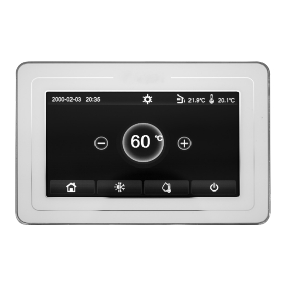
1. USER INTERFACE General characteristics Fig. 1 Home page The display uses a capacitive touch-screen for command input. The screen turns black when the display light goes out (Fig. 1 Home page). This control is highly sensitive and also responds to foreign objects touching the display. It is therefore recommended to keep it clean during use. -
Page 7: Menu Layout
After start-up, the display shows the menu screen page (Home page). On this page it is possible to: • select one of the available user menus; • switch the unit on/off; • view information concerning the operating mode, any active errors, as well as the system date and time. Note: after 10 minutes without any interaction, the display automatically goes back to menu page. -
Page 8: Basic Functions
• Thermostat (page 27) • Floor debug (page • Ctrl. state (page 25) • Other thermal (page • Address (pag.32) • Cool 2-way valve (page • Manual defrost (page • Refri. recovery • Optional E-Heater (pag.32) Function • Heat 2-way valve (page (page 29) •... -
Page 9: Menu Selection
Menu selection To open one of the menus available to the user, it is necessary to click on the corresponding icon. Once opened, each menu (depending on the one selected) will allow the user to browse the various pages or to open other sub-menus linked to specific functions. -
Page 10: Activate The Function For Fast Hot Water Production (Fast Hot Water)
• If there is no storage tank, the available modes will only be "Heat" and "Cool"; • If a storage tank is fitted, the "Cool", "Heat", "Cool + Hot water" and "Heat + Hot water" modes will be available, as shown in the image above. -
Page 11: Heating And Dhw Production (Heat+Hot Water)
Heating and DHW production (Heat+Hot water) After opening the "Heat+Hot water" function, user can select the required option. Once the priority has been selected, press "OK" to confirm. Selecting the "Heat" option will force the unit to satisfy the termi- nal side of the system first;... -
Page 12: Weather Depend
Weather depend To navigate this menu, the system provides the following keys: 1. Go to previous page; 2. Go to the following page; 3. Go back to higher level menu; 4. Go back to menu screen page. Fig. 11 "Weather depend" screen page Once entered, click the "Weather depend"... -
Page 13: Weekly Timer
Weekly timer After opening the "Weekly timer" function, user can set up to three time bands for each day of the week during which the unit will operate, using the current mode and set; or it will be possible to assign the "Holiday" value to one or more days, which (if the specific "Holiday release"... -
Page 14: Holiday Release (For Weekly Timer)
• Each day allows the setting of up to three time slots (periods) whose start and end times must be consistent with each other (the start of a period must be after the end of the previous period); • If one or more days have been set as "Holiday", the "Holiday release" function must be activated (see paragraph Holiday release (for Weekly timer) on page 14);... -
Page 15: Clock Timer
Notes: • This function can only be activated if a storage tank is present. If there is no storage tank, this function will not be available; • This function can be set even if the unit is Off; • This function cannot be activated at the same time as the functions: "Emergency mode", "Holiday mode", "Floor debug", "Manual defrost", "Refri. -
Page 16: Temp. Timer
Notes: • If the required mode is "Hot water", the "WOT-Cool" or "WOT-Heat" parameter will not be displayed; • If "Weekly timer" and "Clock Timer" are activated at the same time, Weekly timer will have priority over the other function; •... -
Page 17: Emergen. Mode
• This function will not be available in hot water mode; • This function will be saved in the event of a power failure; • The default value for this function is "Off". 4.13 Emergen. mode In the event that system includes storage tank and/or an addition- al heat source (and they are properly set) (see paragraph Setting an additional heat source (Other thermal) on page 28) or a heat- ing element (see paragraph Optional E-Heater on page 29), it... -
Page 18: Preset Mode
Notes: • This function can only be activated with unit OFF. If that is not so, a message will warn user to switch unit off before changing the operating mode; • When Holiday mode option is active, the operating mode will be automatically set to "Heat" and it will not be possible to set the mode and use On/Off commands on the control unit;... -
Page 19: Error Reset
4.16 Error Reset This function allows the errors currently active on the system to be reset. This operation must only be performed after the report- ed alarm condition has been resolved. To reset the alarms, it will be necessary to press on the function label, and then confirm the operation by pressing the "OK"... -
Page 20: Set Temperature Set-Points To Be Used By The Unit In The Various Modes
Set temperature set-points to be used by the unit in the various modes Through the windows of this menu, it will be possible to set the values to be used as working set-points for the various modes. The way you can edit and save the values is always the same: click the label of the chosen parameter, and set the required val- ue using the "+"... -
Page 21: Viewing The Status Of Unit Components (Status)
Viewing the status of unit components (Status) This page shows the status of the various system components. After opening the"Status" function, user can browse the available pages using the keys on the right and left side of the window. The table below lists the available details and possible statuses. Note: all information under this menu is in read-only mode. -
Page 22: Viewing The Status Of Unit Parameters (Parameter)
Viewing the status of unit parameters (Parameter) These pages will show current values for the unit operating parameters. After opening the "Parameter" function, user can browse the available pages using the keys on the right and left side of the window. The table below lists the available details. Note: all information under this menu is in read-only mode. - Page 23 Full name Displayed name Code Fan error Outdoor fan High pressure protection High pressure Low pressure protection Low pressure High discharge temperature protection Hi-discharge Capacity DIP switch fault Capacity DIP Communication error between external and internal main boards ODU-IDU Com. Communication error between external main board and drive board Drive-main com.
-
Page 24: Error List
Full name Displayed name Code Reset of the driver Driver reset Compressor overcurrent Com. over-cur. Current sensor circuit fault or current sensor fault Current sen. Desynchronisation Desynchronize Overtemperature of radiator or IPM or PFC Overtemp.-mod. Temperature sensor fault of radiator or IPM or PFC T-mod. -
Page 25: Setting The Control Logic (Ctrl. State)
To browse the "Function" o "Parameter" sub-menu, the system provides the following keys: 1. Go to previous page; 2. Go to the following page; 3. Go back to higher level menu; 4. Go back to menu screen page. To open a function, click on the corresponding text. Fig. -
Page 26: Heat 2-Way Valve
Notes: • Select status "Off" for the valve to be CLOSED in cooling mode. Select status "On" for the valve to be OPEN; • The setting will be saved in the event of a power failure. Heat 2-way valve After opening the "Heat 2-way valve" function, user can set the status of the 2-way valve in Heat mode. -
Page 27: Thermostat
Notes: • If there is no storage tank, hot water production modes will NOT be available; • The unit must be off before user can edit the parameter; • This setting will be saved in the event of a power failure. Thermostat After opening the "Thermostat"... -
Page 28: Setting An Additional Heat Source (Other Thermal)
Setting an additional heat source (Other thermal) After opening the "Other thermal" function, user can activate or deactivate the additional heat source, set an external tempera- ture threshold below which it must be activated instead of the heat pump, as well as the logic applicable for managing the re- placement. -
Page 29: Optional E-Heater
Optional E-Heater After opening the "Optional E-Heater" function, user can activate or deactivate any additional electric heater. Said electric heat- er may have a single or double stage resistor (in case of dou- ble-stage resistor user can decide whether to use both stages by specifying the number of resistors in the first parameter). -
Page 30: Air Removal
Notes: • The "T-room" option of "Ctrl. state" function will be only available if the Remote sensor is activated; • This setting will be saved in the event of a power failure. 7.11 Air removal After opening the "Air removal" function, user can activate (inside the selected circuit) water circulation to bleed any air in the circuit. -
Page 31: Manual Defrost
7.13 Manual defrost After opening the "Manual defrost" function, user can activate or deactivate the control for forced execution of a defrost cycle. Once the required item has been selected, press "OK" to confirm. Fig. 42 "Manual defrost" screen page Notes: •... -
Page 32: Setting Limit Absorption
7.16 Setting limit absorption After opening the "C/P limit" function, user can select either "On" or "Off" settings. Select "On" to set the limit value for current. To save this setting, click "Save" icon on top right-hand corner. Fig. 45 "C/P limit " screen page Note: This setting will be saved in the event of a power failure. -
Page 33: Logic For Managing Water Tank Electric Heater (Tank Heater)
7.19 Logic for managing water tank electric heater (Tank heater) After opening the "Tank heater" function, user can select the logic to be used to manage water tank electric heater. Available logics are as follows: • Logic 1: the unit compressor and water tank electric heater can not work simultaneously;... - Page 34 Displayed name Possible values Preset setting Note 3 min (2-way valve If set time for "Cool Run disabled) Time" parameter has expired and the temper- Cool Run Time 1 - 10 min ature difference remains 5 min (2-way valve in the standby range, the enabled) unit will stop.
- Page 35 4. Back light: it will be possible to choose whether to use the "Lighted" logic (display always on), or the "Energy save" that will turn display off after 5 minutes of inactivity (press on display to turn it automatically back on). 5.
- Page 36 Fax +39 0365 878 304 e-mail: info@fondital.it www.fondital.com The manufacturer reserves the right to modify his/her products as deemed necessary, without alter- ing the basic characteristics of the products themselves. Uff. Pubblicità Fondital IST 03 J 047 - 01 | Luglio 2022 (07/2022)
Need help?
Do you have a question about the PROCIDA AWM and is the answer not in the manual?
Questions and answers