
Summary of Contents for Thermo King SG 3500 Series
- Page 1 Maintenance Manual Container Edition SG 3500 Series Revision A T T K K 6 6 1 1 9 9 1 1 4 4 - - 4 4 - - M M M M - - E E N N April 2022...
-
Page 2: P P H H O O T T O O S S , , I I L L L L U U S S T T R R A A T T I I O O N N S S , , A A N N D D M M E E A A S S U U R R E E M M E E N N T T S
This manual is published for informational purposes only. Thermo King® makes no representations warranties express or implied, with respect to the information recommendations and descriptions contained herein. Information provided should not be regarded as all-inclusive or covering all contingencies. If further information is required, Thermo King Corporation Service Department should be consulted. - Page 3 I I n n t t r r o o d d u u c c t t i i o o n n Customer Satisfaction Survey Let your voice be heard! Your feedback will help improve our manuals. The survey is accessible through any internet-connected device with a web browser.
-
Page 4: Table Of Contents
SG 3500 Series Unit Weight........ - Page 5 T T a a b b l l e e o o f f C C o o n n t t e e n n t t s s SGUM 3500 Front View............... . . 28 SGUM 3500 Front View (Covers Removed).
-
Page 6: S S T T R R U U C C T T U U R R A A L L / / A A C C C C E E S S S S O O R R Y Y M M A A I I N N T T E E N N A A N N C C E
T T a a b b l l e e o o f f C C o o n n t t e e n n t t s s Pre-trip Testing ................46 Manual Speed Control . - Page 7 Yanmar Diagnostic Trouble Codes (DTC) and Associated Thermo King Alarm Codes ....91 Clearing Yanmar DTC Codes and Associated Thermo King Alarm Codes ......91 Connecting and Using the Yanmar Engine Diagnostic Tool .
- Page 8 T T a a b b l l e e o o f f C C o o n n t t e e n n t t s s Generator Bearing............... . . 112 Impeller Fan .
-
Page 9: Danger, Warning, Caution, And Notice
Safety Precautions Danger, Warning, Caution, and Notice Thermo King® recommends that all service be performed by a Thermo King dealer and to be aware of several general safety practices. Safety advisories appear throughout this manual as required. Your personal safety and the proper operation of this unit depend upon the strict observance of these precautions. -
Page 10: Electrical Hazards
S S a a f f e e t t y y P P r r e e c c a a u u t t i i o o n n s s N N O O T T I I C C E E E E q q u u i i p p m m e e n n t t D D a a m m a a g g e e ! ! A A l l l l u u n n i i t t m m o o u u n n t t i i n n g g b b o o l l t t s s m m u u s s t t b b e e i i n n s s t t a a l l l l e e d d , , b b e e t t h h e e c c o o r r r r e e c c t t l l e e n n g g t t h h f f o o r r t t h h e e i i r r a a p p p p l l i i c c a a t t i i o o n n , , a a n n d d t t o o r r q q u u e e d d t t o o s s p p e e c c i i f f i i c c a a t t i i o o n n s s . -
Page 11: Low Voltage
S S a a f f e e t t y y P P r r e e c c a a u u t t i i o o n n s s W W A A R R N N I I N N G G P P e e r r s s o o n n a a l l P P r r o o t t e e c c t t i i v v e e E E q q u u i i p p m m e e n n t t ( ( P P P P E E ) ) R R e e q q u u i i r r e e d d ! ! I I n n t t h h e e e e v v e e n n t t o o f f a a n n e e l l e e c c t t r r i i c c a a l l a a c c c c i i d d e e n n t t , , a a l l l l r r e e q q u u i i r r e e d d P P P P E E s s h h o o u u l l d d b b e e n n e e a a r r t t h h e e w w o o r r k k a a r r e e a a i i n n a a c c c c o o r r d d a a n n c c e e w w i i t t h h O O S S H H A A , , N N F F P P E E 7 7 0 0 E E , , o o r r o o t t h h e e r r l l o o c c a a l l , , s s t t a a t t e e , , o o r r c c o o u u n n t t r r y y - - s s p p e e c c i i f f i i c c r r e e q q u u i i r r e e m m e e n n t t s s f f o o r r a a C C a a t t e e g g o o r r y y 2 2 r r i i s s k k . -
Page 12: Battery Removal
S S a a f f e e t t y y P P r r e e c c a a u u t t i i o o n n s s W W A A R R N N I I N N G G H H a a z z a a r r d d o o f f E E x x p p l l o o s s i i o o n n ! ! A A l l w w a a y y s s c c o o v v e e r r b b a a t t t t e e r r y y t t e e r r m m i i n n a a l l s s t t o o p p r r e e v v e e n n t t t t h h e e m m f f r r o o m m m m a a k k i i n n g g c c o o n n t t a a c c t t w w i i t t h h m m e e t t a a l l c c o o m m p p o o n n e e n n t t s s d d u u r r i i n n g g b b a a t t t t e e r r y y i i n n s s t t a a l l l l a a t t i i o o n n . -
Page 13: Controller / Microprocessor Service Precautions
S S a a f f e e t t y y P P r r e e c c a a u u t t i i o o n n s s Controller / Microprocessor Service Precautions Take precautions to prevent electrostatic discharge when servicing the controller or microprocessor and its related components. - Page 14 S S a a f f e e t t y y P P r r e e c c a a u u t t i i o o n n s s • S S k k i i n n : : Remove contaminated clothing. Wash thoroughly with soap and water. Get medical attention if irritation persists.
-
Page 15: Generator
Specifications Generator Type 460/230 Vac, 3 Phase, 60/50 Hz Output Power 15 kW Kilovolt-Amperes 18.75 kVA 1800 RPM Electrical Control System Controls SG–3500 Controller Voltage 12.5 Vdc (nominal) Battery 12 Volts, Group 31, 925 / 950 CCA @ -18 C (0 F) Fuse FS1 (Located in Control Box) 10 Amp - Battery Post to Main Relay Fuse FS2 (Located in Control Box) -
Page 16: Engine
S S p p e e c c i i f f i i c c a a t t i i o o n n s s Engine SG 3500 Model Thermo King TK486VGE1 (EPA Tier IV and 2016/1628 EU regulation (or NRMM Stage V) compliant) Fuel Type Diesel fuel must conform to EN590 Oil Capacity Dry fill: 13.2 liters (14 quart) -
Page 17: Belt Tension
Field Reset (Hz) is recommended. (used belt) Water Pump Belt 126 Hz (40 lbs) 118 Hz (32 lbs) SG 3500 Series Unit Weight Max weight Tare weight 1234 kg (2719.38 lbs.) 852 kg (1879 lbs.) SGCO-3500 764 kg (1684 lbs.) 669 kg (1474 lbs.) - Page 18 Maintenance Inspection Schedule Every Every Pretrip Inspect/Service These Items 1,500 3,000 Hours Hours* Microprocessor: Run Pretrip Test (see “Performing a Pretrip Test”). • Engine: Check fuel supply. • Check engine oil level. • Listen for unusual noises, vibrations, etc. • •...
-
Page 19: General Description
Unit Description General Description Thermo King generator sets (clip-on and under-mount) are self-contained fully-automatic, diesel powered units. The generator sets supply 230 or 460 Vac electrical power for container refrigeration units. Enclosed within the unit frame are the engine, dual voltage alternator, generator battery compartment, battery charging regulator and control panel. -
Page 20: Emi 3000
U U n n i i t t D D e e s s c c r r i i p p t t i i o o n n EMI 3000 These units are equipped with an EMI 3000 Extended Maintenance Interval package. The EMI 3000 package will result in lower total unit life cycle cost, because maintenance intervals have an important impact on unit operating costs. -
Page 21: Microprocessor Controller
U U n n i i t t D D e e s s c c r r i i p p t t i i o o n n Microprocessor Controller BEE796 Unit Protection Devices W W A A R R N N I I N N G G E E q q u u i i p p m m e e n n t t D D a a m m a a g g e e a a n n d d R R i i s s k k o o f f I I n n j j u u r r y y ! ! T T h h e e u u n n i i t t m m a a y y s s t t a a r r t t a a t t a a n n y y t t i i m m e e w w i i t t h h o o u u t t w w a a r r n n i i n n g g w w h h e e n n t t h h e e u u n n i i t t O O n n / / O O f f f f s s w w i i t t c c h h i i n n t t h h e e O O n n p p o o s s i i t t i i o o n n . -
Page 22: Sgco 3500 Front View
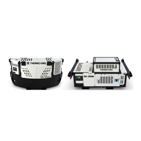
Photos, Illustrations, and Measurements SGCO 3500 Front View BEE783 Fuel Tank Cap Pin mount (option) Control Box Location Front Access Doors Telematics Module Radiator Location Corner Casting Mount TK 61914-4-MM-EN... -
Page 23: Sgco 3500 Front View (Covers Removed)
P P h h o o t t o o s s , , I I l l l l u u s s t t r r a a t t i i o o n n s s , , a a n n d d M M e e a a s s u u r r e e m m e e n n t t s s SGCO 3500 Front View (Covers Removed) BEE784 Control Box Location... -
Page 24: Sgco 3500 Control Box (External)
P P h h o o t t o o s s , , I I l l l l u u s s t t r r a a t t i i o o n n s s , , a a n n d d M M e e a a s s u u r r e e m m e e n n t t s s SGCO 3500 Control Box (External) BEE785 Unit ON / OFF Switch... -
Page 25: Sgco 3500 Telematics Fuel Sensor
P P h h o o t t o o s s , , I I l l l l u u s s t t r r a a t t i i o o n n s s , , a a n n d d M M e e a a s s u u r r e e m m e e n n t t s s SGCO 3500 Telematics Fuel Sensor BEE791 SGCO 3500 Customer asset ID decal... -
Page 26: Sgco 3500 Mechanical Fuel Gauge (Option)
P P h h o o t t o o s s , , I I l l l l u u s s t t r r a a t t i i o o n n s s , , a a n n d d M M e e a a s s u u r r e e m m e e n n t t s s SGCO 3500 Mechanical fuel gauge (Option) BEE793 TK 61914-4-MM-EN... -
Page 27: Control Box Sgco Inside View
P P h h o o t t o o s s , , I I l l l l u u s s t t r r a a t t i i o o n n s s , , a a n n d d M M e e a a s s u u r r e e m m e e n n t t s s Control Box SGCO Inside view BEE941 Quad Relay... -
Page 28: Sgum 3500 Front View
P P h h o o t t o o s s , , I I l l l l u u s s t t r r a a t t i i o o n n s s , , a a n n d d M M e e a a s s u u r r e e m m e e n n t t s s SGUM 3500 Front View BEE786 Fuel Tank Cap... -
Page 29: Sgum 3500 Front View (Covers Removed)
P P h h o o t t o o s s , , I I l l l l u u s s t t r r a a t t i i o o n n s s , , a a n n d d M M e e a a s s u u r r e e m m e e n n t t s s SGUM 3500 Front View (Covers Removed) BEE787 Battery charger... -
Page 30: Sgum 3500 Arms Mounting
P P h h o o t t o o s s , , I I l l l l u u s s t t r r a a t t i i o o n n s s , , a a n n d d M M e e a a s s u u r r e e m m e e n n t t s s SGUM 3500 Arms Mounting BEE923 SGUM 3500 Telematics Fuel Sensor... -
Page 31: Sgco 3500 Control Box (External)
P P h h o o t t o o s s , , I I l l l l u u s s t t r r a a t t i i o o n n s s , , a a n n d d M M e e a a s s u u r r e e m m e e n n t t s s SGCO 3500 Control Box (External) BEE788 Controller... -
Page 32: Control Box Sgum Inside View
P P h h o o t t o o s s , , I I l l l l u u s s t t r r a a t t i i o o n n s s , , a a n n d d M M e e a a s s u u r r e e m m e e n n t t s s Control Box SGUM Inside view BEE942 Fuse block... -
Page 33: Sgum 3500 Installation Decal
P P h h o o t t o o s s , , I I l l l l u u s s t t r r a a t t i i o o n n s s , , a a n n d d M M e e a a s s u u r r e e m m e e n n t t s s SGUM 3500 Installation Decal RAJ828 TK 61914-4-MM-EN... - Page 34 Genset Model Features SGUM 3500 SGCO 3500 Model TK486VGE1 460 Vac Output for 15 KW, 18.75 KVA, 3 Phase, 60 Hz, 4 Wire Generator 230 Vac Output for 15 KW, 18.75 KVA, 3 Phase, 60 Hz, 4 Wire Generator SG 3500 Control System Battery with Post Battery Charging System, Solid-state —...
-
Page 35: Controller Description
Controller and Operating Instructions Controller Description The controller is a one-piece, self contained microprocessor for diesel generator sets. The display and microprocessor is mounted in the cover. Six external relays - Main relay, Starter relay, Air Heater relay, Injector Actuator relay, Charger relay and Quad relay are also mounted inside the control box near the microprocessor. -
Page 36: Navigating The Controller Menus
C C o o n n t t r r o o l l l l e e r r a a n n d d O O p p e e r r a a t t i i n n g g I I n n s s t t r r u u c c t t i i o o n n s s •... -
Page 37: Operating Instructions
C C o o n n t t r r o o l l l l e e r r a a n n d d O O p p e e r r a a t t i i n n g g I I n n s s t t r r u u c c t t i i o o n n s s Operating Instructions Pretrip Inspection The pretrip inspection is an important part of the preventive maintenance program. -
Page 38: Controller Interaction And Display
Controller Display Splash Screen Thermo King/Marine logo to be displayed as a splash screen for 10 seconds when the controller is switched on. Active Display The controller screen is to remain illuminated for 10 minutes whenever the unit is powered on. Following that 10 min duration, the back light can be switched off, and will resume whenever a key is pressed. -
Page 39: Flashloading The Controller
C C o o n n t t r r o o l l l l e e r r a a n n d d O O p p e e r r a a t t i i n n g g I I n n s s t t r r u u c c t t i i o o n n s s Flashloading the controller 1. - Page 40 C C o o n n t t r r o o l l l l e e r r a a n n d d O O p p e e r r a a t t i i n n g g I I n n s s t t r r u u c c t t i i o o n n s s 5.
-
Page 41: Controller Display Menu
C C o o n n t t r r o o l l l l e e r r a a n n d d O O p p e e r r a a t t i i n n g g I I n n s s t t r r u u c c t t i i o o n n s s Controller Display Menu N N o o t t e e : : The Data Menu only displays information, items can NOT be changed. -
Page 42: Alarms
C C o o n n t t r r o o l l l l e e r r a a n n d d O O p p e e r r a a t t i i n n g g I I n n s s t t r r u u c c t t i i o o n n s s •... - Page 43 C C o o n n t t r r o o l l l l e e r r a a n n d d O O p p e e r r a a t t i i n n g g I I n n s s t t r r u u c c t t i i o o n n s s •...
-
Page 44: Genset Start-Up And Initial Runtime
C C o o n n t t r r o o l l l l e e r r a a n n d d O O p p e e r r a a t t i i n n g g I I n n s s t t r r u u c c t t i i o o n n s s Genset Start-up and Initial Runtime The startup sequence is initiated by the user applying power to the controller by toggling the external switch to the on position. -
Page 45: Post Start
C C o o n n t t r r o o l l l l e e r r a a n n d d O O p p e e r r a a t t i i n n g g I I n n s s t t r r u u c c t t i i o o n n s s Post Start Following a successful start as defined above, and the controller has requested 1500 rpm operation, the controller is to take the following actions:... -
Page 46: Engine Stall
C C o o n n t t r r o o l l l l e e r r a a n n d d O O p p e e r r a a t t i i n n g g I I n n s s t t r r u u c c t t i i o o n n s s –... -
Page 47: Event Logging
C C o o n n t t r r o o l l l l e e r r a a n n d d O O p p e e r r a a t t i i n n g g I I n n s s t t r r u u c c t t i i o o n n s s Event logging All logged events must be logged in non-volatile memory and include a time and date, along with the other specific data called out. -
Page 48: Shutdown Alarms
C C o o n n t t r r o o l l l l e e r r a a n n d d O O p p e e r r a a t t i i n n g g I I n n s s t t r r u u c c t t i i o o n n s s Shutdown Alarms Shutdown Alarms are latching and immediately stop the Generator. - Page 49 C C o o n n t t r r o o l l l l e e r r a a n n d d O O p p e e r r a a t t i i n n g g I I n n s s t t r r u u c c t t i i o o n n s s Alarm ECU current Description...
-
Page 50: Battery
Electrical Maintenance Battery C C A A U U T T I I O O N N R R i i s s k k o o f f I I n n j j u u r r y y ! ! P P l l a a c c e e t t h h e e u u n n i i t t O O n n / / O O f f f f s s w w i i t t c c h h i i n n t t h h e e “... -
Page 51: Battery Charger
E E l l e e c c t t r r i i c c a a l l M M a a i i n n t t e e n n a a n n c c e e Battery charger BEE620 Battery charge... -
Page 52: Microprocessor Controller
E E l l e e c c t t r r i i c c a a l l M M a a i i n n t t e e n n a a n n c c e e Microprocessor Controller BEE796 Fuses... -
Page 53: Unit Wiring
E E l l e e c c t t r r i i c c a a l l M M a a i i n n t t e e n n a a n n c c e e Unit Wiring Inspect the unit wiring and wire harnesses during scheduled maintenance inspections for loose, chaffed or broken wires. -
Page 54: Engine Oil Level Sensor
E E l l e e c c t t r r i i c c a a l l M M a a i i n n t t e e n n a a n n c c e e Engine Oil Level Sensor S S w w i i t t c c h h T T e e s s t t : : 1. -
Page 55: Emi 3000
The EMI package allows standard maintenance intervals to be extended to 3,000 hours, or 2 years, whichever occurs first. N N o o t t e e : : Units equipped with the EMI 3000 package do require regular inspection in accordance with Thermo King's maintenance recommendations. -
Page 56: Oil Filter Change
10. Properly dispose of the used engine oil and filter. Oil Filter Change The oil filter should be changed along with the engine oil. Use a genuine Thermo King extended maintenance oil filter. 1. Remove the filter. 2. Fill the new oil filter with clean engine oil. - Page 57 E E n n g g i i n n e e M M a a i i n n t t e e n n a a n n c c e e Figure 2. Low Oil Pressure Flow Chart TK 61914-4-MM-EN...
-
Page 58: Engine Cooling System
N N o o t t e e : : The new engine coolant, Chevron Extended Life Coolant, is RED in color instead of the current GREEN or BLUE- GREEN colored coolants. Figure 3. ELC Nameplate Located Near Expansion Tank The following are the Extended Life Coolants currently approved by Thermo King for use in ELC units for five years or 12,000 hours: • Chevron Dex-Cool •... -
Page 59: Antifreeze Maintenance Procedure
E E n n g g i i n n e e M M a a i i n n t t e e n n a a n n c c e e • Detroit Diesel POWERCOOL Plus N N o o t t e e : : The use of 50/50 percent pre-mixed Extended Life Coolant (ELC) is recommended to assure that de-ionized water is being used. -
Page 60: Engine Thermostat
E E n n g g i i n n e e M M a a i i n n t t e e n n a a n n c c e e Remove the plug (1) from the front end of the water pump below the thermostat housing as shown (). Slowly pour the coolant into the system until you see coolant at the plug fitting. - Page 61 E E n n g g i i n n e e M M a a i i n n t t e e n n a a n n c c e e 2. Unscrew the coolant level switch to loosen it and remove it from the tank. Place the new coolant level switch in the tank.
-
Page 62: Engine Fuel System
Fuel System Fittings I I m m p p o o r r t t a a n n t t : : Using the wrong fuel system fittings may void your engine warranty! All Thermo King supplied fuel line fittings (except fuel line connector) are nickel plated brass. -
Page 63: Fuel Return Line Replacement
E E n n g g i i n n e e M M a a i i n n t t e e n n a a n n c c e e • Fuel tank and filter system maintenance. •... -
Page 64: Bleeding The Fuel System
E E n n g g i i n n e e M M a a i i n n t t e e n n a a n n c c e e Bleeding the Fuel System SG 3500 Series If the engine runs out of fuel, fuel filters replaced, repairs are made to the fuel system, or air gets into the system for any other reason, air must be bled out of the fuel system to prevent interrupted unit operation or possibly severe damage to the high pressure fuel pump. -
Page 65: Filter Icon Identification
E E n n g g i i n n e e M M a a i i n n t t e e n n a a n n c c e e Filter Icon Identification The icons shown below are located on the fuel filter label. Use the table below for label identification. 27+/- 2.7Nm DRAIN DAILY... -
Page 66: Injection Pump Removal
E E n n g g i i n n e e M M a a i i n n t t e e n n a a n n c c e e Injection Pump Removal The injection pump drive gear will not fit through the gear housing when removing the pump, the gear must be separated from the pump. -
Page 67: Injection Pump Reinstallation
E E n n g g i i n n e e M M a a i i n n t t e e n n a a n n c c e e 5. Align the threaded holes in the injection pump gear with the two holes in the tool plate by rotating the engine crankshaft. -
Page 68: Download Procedure For Injection Pump Replacement
E E n n g g i i n n e e M M a a i i n n t t e e n n a a n n c c e e Download Procedure for Injection Pump Replacement This Procedure is carried out using the Yanmar Diagnostic Tool. - Page 69 E E n n g g i i n n e e M M a a i i n n t t e e n n a a n n c c e e 5. Click “Part replacement (download)” on the tab “Operations with ECU Disconnected” 6.
- Page 70 E E n n g g i i n n e e M M a a i i n n t t e e n n a a n n c c e e 7. Move the cursor over “Pump Replacement (Trim Data Copy)” It will turn blue. Then Click it. 8.
- Page 71 E E n n g g i i n n e e M M a a i i n n t t e e n n a a n n c c e e 9. The pump replacement (pump data download) screen is displayed. Enter the model and Serial No., and click “Send”.
- Page 72 E E n n g g i i n n e e M M a a i i n n t t e e n n a a n n c c e e N N o o t t e e : : If you do not enter either the model or unit serial number, the below prompt is displayed. N N o o t t e e : : Make sure that the Internet connection is active.
- Page 73 E E n n g g i i n n e e M M a a i i n n t t e e n n a a n n c c e e 11. A Screen is displayed that lists the downloaded pump replacements (corrected value download). Click the Serial number box.
- Page 74 E E n n g g i i n n e e M M a a i i n n t t e e n n a a n n c c e e 13. Click “Details” on the pump replacement (correction value download) screen. 14.
- Page 75 E E n n g g i i n n e e M M a a i i n n t t e e n n a a n n c c e e 15. On the Pump Replacement (correction value download) List screen, select “DL” next to the Part Name that you wish to download data for.
- Page 76 E E n n g g i i n n e e M M a a i i n n t t e e n n a a n n c c e e 16. The Pump Replacement (correction value download) process starts. 17.
- Page 77 E E n n g g i i n n e e M M a a i i n n t t e e n n a a n n c c e e Injection Pump Replacement (Execution) 1. Click “FIE Replacement (Execution)” on the tab “ECU Access”. 2.
- Page 78 E E n n g g i i n n e e M M a a i i n n t t e e n n a a n n c c e e 4. The ECU Write Screen is displayed. Move the cursor over “Pump Replacement (Trim data write)”. 5.
- Page 79 E E n n g g i i n n e e M M a a i i n n t t e e n n a a n n c c e e 6. The Operation Selection Screen is Displayed. Select “Download data”. Click Next. N N o o t t e e : : In the case of “Manual Input”...
- Page 80 E E n n g g i i n n e e M M a a i i n n t t e e n n a a n n c c e e 9. The Operation Selection Screen is displayed. Select “Manual Input”, and click “Next. 10.
- Page 81 E E n n g g i i n n e e M M a a i i n n t t e e n n a a n n c c e e 11. The Data Setting Screen is displayed. Manually enter the correction values. 12.
- Page 82 E E n n g g i i n n e e M M a a i i n n t t e e n n a a n n c c e e N N o o t t e e : : If a value has not been entered or if the check data is incorrect, the below error screen is displayed. 13.
- Page 83 E E n n g g i i n n e e M M a a i i n n t t e e n n a a n n c c e e 15. A screen with the necessary procedures after the ECU writing process is displayed. When the confirmation screen is displayed, click “OK”.
-
Page 84: Engine Valve Clearance Adjustment
E E n n g g i i n n e e M M a a i i n n t t e e n n a a n n c c e e 18. Click “OK” on the message box for the report creation notification to return to the below screen. Click “Cancel” to return to the main menu. - Page 85 E E n n g g i i n n e e M M a a i i n n t t e e n n a a n n c c e e Index Mark Top Dead Center Mark for 1 and 4 b.
-
Page 86: Crankcase Breather
E E n n g g i i n n e e M M a a i i n n t t e e n n a a n n c c e e Valve Adjustments and Cylinder Configurations Rear Flywheel Front Pulley End Cylinder Number Valve arrangement... -
Page 87: Emi 3000 Air Cleaner
E E n n g g i i n n e e M M a a i i n n t t e e n n a a n n c c e e Crankcase Typical Cause Pressure Effect Increase Piston Rings Stuck or Worn Increase Breather Hose or Restrictor Plugged... -
Page 88: Water Pump Belt
E E n n g g i i n n e e M M a a i i n n t t e e n n a a n n c c e e Water Pump Belt The water pump pulley is a split type. Adjust the tension by adding or removing shims between the pulley sheaves. See the specification chapter for the correct water pump belt tension settings.“,”... -
Page 89: Radiator And Fan Service
E E n n g g i i n n e e M M a a i i n n t t e e n n a a n n c c e e Nm). I I m m p p o o r r t t a a n n t t : : Belt tension is adjusted by adding, removing, or changing the thickness of shims between the water pump pulley sheaves. -
Page 90: Radiator Cooling Fan
E E n n g g i i n n e e M M a a i i n n t t e e n n a a n n c c e e Radiator Cooling Fan The radiator cooling fan on SG units are driven directly off of the engine. •... -
Page 91: Yanmar Diagnostic Trouble Codes (Dtc) And Associated Thermo King Alarm Codes
Alarm Codes When a Yanmar DTC Code is set, a corresponding 300 Series Thermo King Alarm Code is also set. The 300 Series Alarm Code is a general indication of what issues may exist. Always connect the Yanmar Service Tool and read all existing DTC codes. - Page 92 C C o o n n n n e e c c t t i i o o n n : : There are three connections from the Thermo King Base Controller to the Yanmar Engine Control Unit (ECU): •...
- Page 93 Y Y a a n n m m a a r r Y Y S S A A D D D D i i a a g g n n o o s s t t i i c c E E n n g g i i n n e e S S e e r r v v i i c c e e Table 1.
- Page 94 Y Y a a n n m m a a r r Y Y S S A A D D D D i i a a g g n n o o s s t t i i c c E E n n g g i i n n e e S S e e r r v v i i c c e e Table 1.
-
Page 95: Software Download For Flash To Replacement Ecu
Y Y a a n n m m a a r r Y Y S S A A D D D D i i a a g g n n o o s s t t i i c c E E n n g g i i n n e e S S e e r r v v i i c c e e Table 1. - Page 96 Y Y a a n n m m a a r r Y Y S S A A D D D D i i a a g g n n o o s s t t i i c c E E n n g g i i n n e e S S e e r r v v i i c c e e used to communicate with the Yanmar Engine Control Unit (ECU).
- Page 97 Y Y a a n n m m a a r r Y Y S S A A D D D D i i a a g g n n o o s s t t i i c c E E n n g g i i n n e e S S e e r r v v i i c c e e Table 2.
- Page 98 Y Y a a n n m m a a r r Y Y S S A A D D D D i i a a g g n n o o s s t t i i c c E E n n g g i i n n e e S S e e r r v v i i c c e e Table 2.
-
Page 99: Uploading Information To Yanmar
Y Y a a n n m m a a r r Y Y S S A A D D D D i i a a g g n n o o s s t t i i c c E E n n g g i i n n e e S S e e r r v v i i c c e e Uploading Information to Yanmar P P u u r r p p o o s s e e : : To send ECU software back to database after ECU flash or if flash was cancelled. -
Page 100: Updating Ecu Software From Yanmar Core Database
Y Y a a n n m m a a r r Y Y S S A A D D D D i i a a g g n n o o s s t t i i c c E E n n g g i i n n e e S S e e r r v v i i c c e e Updating ECU Software From Yanmar Core Database P P u u r r p p o o s s e e : : To reprogram ECU / Required Data Exchange. - Page 101 Y Y a a n n m m a a r r Y Y S S A A D D D D i i a a g g n n o o s s t t i i c c E E n n g g i i n n e e S S e e r r v v i i c c e e Table 4.
- Page 102 Y Y a a n n m m a a r r Y Y S S A A D D D D i i a a g g n n o o s s t t i i c c E E n n g g i i n n e e S S e e r r v v i i c c e e Table 4.
- Page 103 Y Y a a n n m m a a r r Y Y S S A A D D D D i i a a g g n n o o s s t t i i c c E E n n g g i i n n e e S S e e r r v v i i c c e e Table 4.
- Page 104 Y Y a a n n m m a a r r Y Y S S A A D D D D i i a a g g n n o o s s t t i i c c E E n n g g i i n n e e S S e e r r v v i i c c e e Table 4.
-
Page 105: Ecu Recovery/Failures During Flash Load Procedures
Y Y a a n n m m a a r r Y Y S S A A D D D D i i a a g g n n o o s s t t i i c c E E n n g g i i n n e e S S e e r r v v i i c c e e ECU Recovery/Failures During Flash Load Procedures P P u u r r p p o o s s e e : : In case of power failure or accidental disconnect etc. - Page 106 Y Y a a n n m m a a r r Y Y S S A A D D D D i i a a g g n n o o s s t t i i c c E E n n g g i i n n e e S S e e r r v v i i c c e e Table 5.
- Page 107 Y Y a a n n m m a a r r Y Y S S A A D D D D i i a a g g n n o o s s t t i i c c E E n n g g i i n n e e S S e e r r v v i i c c e e Table 5.
-
Page 108: Communication Interruption During Flashing Process
Y Y a a n n m m a a r r Y Y S S A A D D D D i i a a g g n n o o s s t t i i c c E E n n g g i i n n e e S S e e r r v v i i c c e e Communication Interruption During Flashing Process Table 6. -
Page 109: Accessing And Downloading Ysad Troubleshooting Manual
Y Y a a n n m m a a r r Y Y S S A A D D D D i i a a g g n n o o s s t t i i c c E E n n g g i i n n e e S S e e r r v v i i c c e e Accessing and Downloading YSAD Troubleshooting Manual Downloading this manual will allow the technician to access much more information while diagnosing engine trouble codes. - Page 110 Y Y a a n n m m a a r r Y Y S S A A D D D D i i a a g g n n o o s s t t i i c c E E n n g g i i n n e e S S e e r r v v i i c c e e RAJ670 5.
- Page 111 Y Y a a n n m m a a r r Y Y S S A A D D D D i i a a g g n n o o s s t t i i c c E E n n g g i i n n e e S S e e r r v v i i c c e e RAJ672 7.
-
Page 112: Megohmmeter
Alternator Operation and Diagnosis Megohmmeter The use of a megohmmeter can be a valuable addition to the repair and maintenance of the generator set. The megohmmeter is essentially a high-range resistance meter (ohmmeter) with a built-in direct-current generator. This meter is of special construction with both current and voltage coils-enabling true ohms to be read directly, independently of the actual voltage applied. -
Page 113: Impeller Fan
A A l l t t e e r r n n a a t t o o r r O O p p e e r r a a t t i i o o n n a a n n d d D D i i a a g g n n o o s s i i s s Impeller Fan Visually inspect the impeller fan to ascertain that no vanes are missing. - Page 114 A A l l t t e e r r n n a a t t o o r r O O p p e e r r a a t t i i o o n n a a n n d d D D i i a a g g n n o o s s i i s s Figure 15.
-
Page 115: General Description
A A l l t t e e r r n n a a t t o o r r O O p p e e r r a a t t i i o o n n a a n n d d D D i i a a g g n n o o s s i i s s General Description The 460/230 Vac alternator consists of three principal components: the main alternator, the integral direct-connected exciter, and an externally mounted excitation control system. -
Page 116: Alternator Function
A A l l t t e e r r n n a a t t o o r r O O p p e e r r a a t t i i o o n n a a n n d d D D i i a a g g n n o o s s i i s s Alternator Function Starting Excitation The initial excitation for the alternator is supplied by residual magnetism in the main field. -
Page 117: Alternator Diagnosis
A A l l t t e e r r n n a a t t o o r r O O p p e e r r a a t t i i o o n n a a n n d d D D i i a a g g n n o o s s i i s s Alternator Diagnosis Preliminary Checks W W A A R R N N I I N N G G... -
Page 118: Test 1 - Determine If Problem Is With The Dsr Or The Alternator
A A l l t t e e r r n n a a t t o o r r O O p p e e r r a a t t i i o o n n a a n n d d D D i i a a g g n n o o s s i i s s N N o o t t e e : : Using a flashlight visually inspect exciter rotor for signs of being burnt, if burnt replace alternator. - Page 119 A A l l t t e e r r n n a a t t o o r r O O p p e e r r a a t t i i o o n n a a n n d d D D i i a a g g n n o o s s i i s s Figure 17.
-
Page 120: Test 4- Exciter And Diode Test
A A l l t t e e r r n n a a t t o o r r O O p p e e r r a a t t i i o o n n a a n n d d D D i i a a g g n n o o s s i i s s Test 4- Exciter and Diode Test Test 4 covers testing the exciter and diodes. - Page 121 A A l l t t e e r r n n a a t t o o r r O O p p e e r r a a t t i i o o n n a a n n d d D D i i a a g g n n o o s s i i s s Figure 18.
- Page 122 A A l l t t e e r r n n a a t t o o r r O O p p e e r r a a t t i i o o n n a a n n d d D D i i a a g g n n o o s s i i s s RAJ872 TK 61914-4-MM-EN...
-
Page 123: Alternator Replacement
A A l l t t e e r r n n a a t t o o r r O O p p e e r r a a t t i i o o n n a a n n d d D D i i a a g g n n o o s s i i s s Alternator Replacement Alternator Removal When removing the alternator from the engine do not separate the stator and rotor, remove as one assembly. -
Page 124: Alternator Installation
A A l l t t e e r r n n a a t t o o r r O O p p e e r r a a t t i i o o n n a a n n d d D D i i a a g g n n o o s s i i s s 4. - Page 125 A A l l t t e e r r n n a a t t o o r r O O p p e e r r a a t t i i o o n n a a n n d d D D i i a a g g n n o o s s i i s s 4.
-
Page 126: Unit Inspection
Structural/Accessory Maintenance Unit Inspection Inspect the unit during unit pre-trip inspection and scheduled maintenance intervals. Look for loose or broken wires or hardware, and other physical damage which might affect unit performance. Repair if required. N N o o t t e e : : See Maintenance Inspection Schedule chapter in this manual for the correct service interval for your unit. 250 or 500 hour inspection/service intervals are required in extreme operating conditions. -
Page 127: Sgco Clip-On Corner Clamp Unit Installation
S S t t r r u u c c t t u u r r a a l l / / A A c c c c e e s s s s o o r r y y M M a a i i n n t t e e n n a a n n c c e e SGCO Clip-on Corner Clamp Unit Installation C C A A U U T T I I O O N N R R i i s s k k o o f f I I n n j j u u r r y y ! ! - Page 128 S S t t r r u u c c t t u u r r a a l l / / A A c c c c e e s s s s o o r r y y M M a a i i n n t t e e n n a a n n c c e e 1.
- Page 129 S S t t r r u u c c t t u u r r a a l l / / A A c c c c e e s s s s o o r r y y M M a a i i n n t t e e n n a a n n c c e e 7.
-
Page 130: Sgco Clip-On Corner Header Pin Unit Installation
S S t t r r u u c c t t u u r r a a l l / / A A c c c c e e s s s s o o r r y y M M a a i i n n t t e e n n a a n n c c e e SGCO Clip-on Corner Header Pin Unit Installation 1. -
Page 131: Telematics General Description
Telematics Information Telematics General Description The telematics system allows the unit owner real-time remote genset monitoring and management access. This system monitors and communicates the following information to the unit owner through the Thermo King Telematics System: • Asset Name •... -
Page 132: Telematics Component Locations
T T e e l l e e m m a a t t i i c c s s I I n n f f o o r r m m a a t t i i o o n n Telematics Component Locations Figure 20. - Page 133 T T e e l l e e m m a a t t i i c c s s I I n n f f o o r r m m a a t t i i o o n n RAJ1052 I I m m p p o o r r t t a a n n t t : : The ability of the device to call in depends on the availability and strength of the GSM / CELL signal.
- Page 134 T T e e l l e e m m a a t t i i c c s s I I n n f f o o r r m m a a t t i i o o n n G G P P S S C C O O M M M M U U N N I I C C A A T T I I O O N N C C Y Y C C L L E E : : Location records are obtained every 10 minutes which can be identified by: •...
-
Page 135: Telematics Diagnostic Information
T T e e l l e e m m a a t t i i c c s s I I n n f f o o r r m m a a t t i i o o n n Telematics Diagnostic Information I I m m p p o o r r t t a a n n t t : : The telematics system (when operating normally) will communicate with the unit owner non-stop - even when the SG unit is turned OFF. - Page 136 T T e e l l e e m m a a t t i i c c s s I I n n f f o o r r m m a a t t i i o o n n RAJ1059 5.
- Page 137 T T e e l l e e m m a a t t i i c c s s I I n n f f o o r r m m a a t t i i o o n n 7.
-
Page 138: Telematics Fuel Level Sensor (Optional)
T T e e l l e e m m a a t t i i c c s s I I n n f f o o r r m m a a t t i i o o n n N N o o t t e e : : The SG controller will show a communication error on the screen of the microprocessor is not communicating. - Page 139 T T e e l l e e m m a a t t i i c c s s I I n n f f o o r r m m a a t t i i o o n n 8.
-
Page 140: Telematics Antenna
T T e e l l e e m m a a t t i i c c s s I I n n f f o o r r m m a a t t i i o o n n 10. - Page 141 T T e e l l e e m m a a t t i i c c s s I I n n f f o o r r m m a a t t i i o o n n Figure 21.
-
Page 142: Pairing Telematics Module To Sg Unit
T T e e l l e e m m a a t t i i c c s s I I n n f f o o r r m m a a t t i i o o n n Pairing Telematics Module to SG Unit I I m m p p o o r r t t a a n n t t : : Each SG unit is uniquely paired to a telematics module on the assembly line: •... - Page 143 T T e e l l e e m m a a t t i i c c s s I I n n f f o o r r m m a a t t i i o o n n 2.
- Page 144 T T e e l l e e m m a a t t i i c c s s I I n n f f o o r r m m a a t t i i o o n n 4.
- Page 145 T T e e l l e e m m a a t t i i c c s s I I n n f f o o r r m m a a t t i i o o n n 9.
- Page 146 T T e e l l e e m m a a t t i i c c s s I I n n f f o o r r m m a a t t i i o o n n 19.
- Page 147 T T e e l l e e m m a a t t i i c c s s I I n n f f o o r r m m a a t t i i o o n n 21.
- Page 148 T T e e l l e e m m a a t t i i c c s s I I n n f f o o r r m m a a t t i i o o n n 25.
-
Page 149: Install Of Telematics In The Sgum-3500
T T e e l l e e m m a a t t i i c c s s I I n n f f o o r r m m a a t t i i o o n n Install of Telematics in the SGUM-3500 1. - Page 150 T T e e l l e e m m a a t t i i c c s s I I n n f f o o r r m m a a t t i i o o n n 3.
- Page 151 Mechanical Diagnosis Table 8. Diagnosing Unit Conditions CONDITION POSSIBLE CAUSE REMEDY Electrical problem Check and repair electrical system Defective starter solenoid Replace solenoid Engine will not crank Repair starter Defective starter Water in cylinders Check for hydrostatic lock. Remove injectors and turn engine slowly Starter motor turns but engine does Starter clutch defective...
-
Page 152: M M E E C C H H A A N N I I C C A A L L D D I I A A G G N N O O S S I I S
M M e e c c h h a a n n i i c c a a l l D D i i a a g g n n o o s s i i s s Table 8. Diagnosing Unit Conditions (continued) CONDITION POSSIBLE CAUSE REMEDY... - Page 153 Diagram Index Drawing No. Drawing Title 3E97558 DIAGRAM WIRING, GENSET SG3500 (4 pages) 3E97559 DIAGRAM SCHEMATIC, GENSET SG3500 (3 pages) TK 61914-4-MM-EN...
- Page 154 E28E ACT-01 ACT-PWR GND-CR SW-05 ELECTRICAL THERMO KING IS THE SOLE OWNER OF THIS DRAWING CHRG-01 CHRG-02 CAD GENERATED DRAWING, AND ALL INFORMATION IN IT, WHICH ARE PROTECTED BY DO NOT MANUALLY UPDATE COPYRIGHT AND OTHER LAWS AND MAY BE SUBJECT TO LAWS REGARDING EXPORTING INFORMATION OUTSIDE OF THE U.S.
- Page 155 Figure 23. 3E97558 (Page 2 of 4) APPROVED 07/Apr/2022 11:35:03 GMT BAT CHG WD1-[2,D] WYE-01 WYE-02 470k%%185 BAT_CHG WD1-[1,F] CH-1 GW-1 RED* RECEPTACLE DSR PCB MAIN FIELD 1.67 %%185 ROTOR ASSY EXCITER ELECTRICAL 10.6%%185 SIZE CODE IDENT NO DWG NO 3E97558 SCALE: NONE REF DWG:...
- Page 156 Figure 24. 3E97558 (Page 3 of 4) APPROVED 07/Apr/2022 11:35:03 GMT REVISIONS CHANGE NOTICE DESCRIPTION DATE APPROVED INITIAL RELEASE 22/12/20 R.BURNHAM 1477136 1509916 CHANGE RED-01 FROM STR 87 TO MAIN 87 17/09/21 J.FERREIRA CHANGE 485-N-01 FROM CTRL-2-10 TO CTRL-2-11,485-P-01 FROM CTRL-2-11 TO CTRL-2-10 1515519 REPLACE GND_OLS WITH OLS_2 AND CONNECT TO BAT-POST-06,ADD WIFP-01 FROM CTRL-3-3 11/11/21...
- Page 157 Figure 25. 3E97558 (Page 4 of 4) APPROVED 07/Apr/2022 11:35:03 GMT WIRE CODE COMPONENT NAME FROM CONNECTOR FROMFROM PORT COMPONENT NAME TOCONNECTOR TO TO PORT WIRE CODE COMPONENT NAME FROM CONNECTOR FROMFROM PORT COMPONENT NAME TOCONNECTOR TO TO PORT 485-N-01 CON_GT_MAL 3A86279H15 CTRL-2...
- Page 158 APS-3 APS-2 APS-1 RPM-2 RPM-1 THERMO KING IS THE SOLE OWNER OF THIS DRAWING CAD GENERATED DRAWING, AND ALL INFORMATION IN IT, WHICH ARE PROTECTED BY DO NOT MANUALLY UPDATE COPYRIGHT AND OTHER LAWS AND MAY BE SUBJECT TO LAWS REGARDING EXPORTING INFORMATION OUTSIDE OF THE U.S.
- Page 159 Figure 27. 3E97559 (Page 2 of 3) APPROVED 07/Apr/2022 11:35:13 GMT DSE 6310 QR-87 QR-30 QUAD DSR-8-1 DSR-3-1 470k%%185 DSR-14-1 DSR-6-1 DSR-15-1 DSR-9-1 EXCITER OPTO ISOLATOR DSR-1-1 10.6%%185 DSR-2-1 CTRL-1-1 CTRL-1-2 CTRL-1-3 CTRL-1-4 460V-1 460V-2 460V-3 GRD-4 RECEPTACLE SW-05 SW-05 SD1-[2,E] BAT_CHG_HV-1 CHRG-01...
- Page 160 Figure 28. 3E97559 (Page 3 of 3) APPROVED 07/Apr/2022 11:35:13 GMT SCHEMATIC LEGEND REF_DES DESCRIPTION LOCATION 12VDC BATTERY TK_Circuit/SD1-[4,H] INJECTION PUMP ACTUATOR TK_Circuit/SD1-[2,C] ACTR ACTUATOR RELAY TK_Circuit/SD1-[2,F] AIR HEATER RELAY TK_Circuit/SD1-[4,D] ATMOSPHER PRESSURE SWITCH TK_Circuit/SD1-[2,C] BAT_CHG BATTERY CHARGER TK_Circuit/SD2-[2,E] COOLANT LEVEL SWITCH TK_Circuit/SD1-[2,H] CON_GT CONNECTOR GT...
- Page 161 N N o o t t e e s s TK 61914-4-MM-EN...
- Page 162 N N o o t t e e s s TK 61914-4-MM-EN...
- Page 163 N N o o t t e e s s TK 61914-4-MM-EN...
- Page 164 1938. For more information, visit www.thermoking.com or www.tranetechnologies.com. Thermo King has a policy of continuous product and product data improvements and reserves the right to change design and specifications without notice. We are committed to using environmentally conscious print practices.
Need help?
Do you have a question about the SG 3500 Series and is the answer not in the manual?
Questions and answers