Table of Contents
Advertisement
Quick Links
Advertisement
Table of Contents

Related Manuals for ARS FlexiBowl

Summary of Contents for ARS FlexiBowl
- Page 1 INSTRUCTIONS FOR USE AND WARNINGS ENGLISH TRANSLATION OF THE ORIGINAL INSTRUCTIONS FlexiBowl® remote control box Revision 1 - Edition 08/2021 ARS S.r.l. Via G. Vico, 7 - 52100 Arezzo (AR) Italy Tel. +39 0575 398611 - Fax +39 0575 398620...
-
Page 2: Table Of Contents
ELECTRICAL CONNECTIONS ..............................9 Standard electrical and user interface connections .............................. 9 Additional electrical connections on the box side ..............................10 Electrical connections on FlexiBowl side ..................................11 Box-FlexiBowl electrical connection procedure ..............................12 4.4.1 Box casing removal ......................................... 12 4.4.2... - Page 3 FlexiBowl® remote control box PAGE INTENTIONALLY LEFT BLANK...
-
Page 4: Preliminary Information
Instructions for use and warnings Preliminary information Purpose The external control box for FlexiBowl® can be used in dirty environments or where there is conductive dust that could cause malfunctions or failures of the electronic components contained inside the supply unit. Components The table below contains the main components found inside FlexiBowl®... -
Page 5: Layout
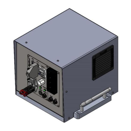
FlexiBowl® remote control box 2 Layout Dimensions Net weight Weight Net weight 15 Kg CHAPTER 2 – LAYOUT... -
Page 6: Transport And Installation
Packaging The machine is shipped by ARS s.r.l. from the production factory to the Customer’s premises. Based on the distance it needs to be transported, on the specific requests from the Customer, and on how long the load will remain in the packaging, the machine will be shipped in the following ways: normal protective packaging for short and medium distances;... -
Page 7: Transport And Handling
If damage is found, it is mandatory to immediately inform the Manufacturer. CAUTION! ARS S.r.l. shall not be held liable for damage, to property or to people, due to accidents caused by failure to follow the instructions in this manual. -
Page 8: Connections
It is the user’s responsibility to guarantee the requested connection characteristics. CAUTION! The required connections must be set up by qualified and authorised personnel. IMPORTANT! For further information on starting up the box, refer to the attached FlexiBowl® User Manual. CHAPTER 3 - TRANSPORT AND INSTALLATION... -
Page 9: Electrical Connections
FlexiBowl® remote control box 4 Electrical connections Standard electrical and user interface connections Standard electrical and user interface connections on the box are identical to those on the FlexiBowl® control panel. Below are: 110/220 Vac power supply connection with relative switch; Inputs connector;... -
Page 10: Additional Electrical Connections On The Box Side
The additional electrical connections have the purpose of connecting the components inside the box with the components inside the FlexiBowl®. They are normally not visible, as all connections are set up inside the supply unit. Below are: Motor electrical power supply cables: this provides the electrical power supply to the motor;... -
Page 11: Electrical Connections On Flexibowl Side
+24 Vdc power supply to the backlighting (if applicable). The arrangement of the cables leading out of the FlexiBowl panel cable gland support is identical to that of the box-side panel. The cables will only be connected to the FlexiBowl part; the connection to the box is set up by the end customer. -
Page 12: Box-Flexibowl Electrical Connection Procedure
Instructions for use and warnings 4.4 Box-FlexiBowl electrical connection procedure 4.4.1 Box casing removal To remove the box casing, observe the following procedure: Unscrew the 6 fixing screws. CHAPTER 4 - ELECTRICAL CONNECTIONS... -
Page 13: Cable Gland Support Disassembly
FlexiBowl® remote control box Remove the casing, pulling it upwards. For the next fixing procedure, position the casing back in place, inserting it from above and proceeding to tighten the screws. 4.4.2 Cable gland support disassembly To take down the box-side cable gland, observe the following procedure: Take the cable gland support down from the panel, removing the two screws marked in the figure. - Page 14 Instructions for use and warnings Remove the fixing screws and take out the plastic edge. CHAPTER 4 - ELECTRICAL CONNECTIONS...
- Page 15 FlexiBowl® remote control box Remove the cable glands from their support and insert the relative cables in the order listed in the previous paragraph. For the next re-assembly operation, re-insert the cable glands into the support and once the edge is re-inserted, proceed with tightening the screws.
-
Page 16: Electrical Cable Connection
Instructions for use and warnings 4.4.3 Electrical cable connection CAUTION! Before doing any electrical connections, it is important to ensure that the machine is turned off. For the connection of the motor, encoder, backlight (if applicable) cables and emptying sliding block sensor (if applicable), perform the following procedure: Insert the motor cable into the relative cable gland (refer to the “Cable gland support disassembly”... - Page 17 FlexiBowl® remote control box Insert the encoder cable into the relative cable gland (refer to the “Cable gland support disassembly” paragraph) and connect the relative connector to the matching slot on the driver. CHAPTER 4 - ELECTRICAL CONNECTIONS...
- Page 18 Instructions for use and warnings Insert the backlight (if applicable) and emptying sliding block sensor (if applicable) cables on the relative cable gland (refer to the “Cable gland support disassembly” paragraph) and connect the relative connectors to the matching slots on the board (“BACKLIGHT”...
-
Page 19: Pneumatic Connections
FlexiBowl® remote control box 5 Pneumatic connections Standard pneumatic connections The standard pneumatic connections on the box are similar to those on the FlexiBowl® control panel. The following are listed: AIR SUPPLY" inlet. CAUTION! Never exceed 6 bar pressure in the machine's pneumatic system. -
Page 20: Additional Pneumatic Connections On Box Side
The purpose of the additional pneumatic connections is to connect the components inside the box with the components inside the FlexiBowl®. Normally they are not visible as all connections are made inside the power supply unit. The following are listed: “AIR OUT”... -
Page 21: Pneumatic Connections On Flexibowl Side
Pneumatic connections on FlexiBowl side Their purpose is to connect the components inside the box with the components inside the FlexiBowl®. The following are listed: “AIR IN” inlet: receives compressed air from the box ("AIR OUT") for supplying the blow and/or emptying solenoid valves (if installed) inside the FlexiBowl;... -
Page 22: Box-Flexibowl Pneumatic Connection Procedure
Connect one end of the first hose to the "FLIP OUT" outlet of the additional control panel of the box: Connect the other end of the first hose to the "FLIP IN" inlet of the FlexiBowl® panel: CAPITOLO 5 – CONNESSIONI PNEUMATICHE... -
Page 23: Blow/Emptying Pneumatic Connection Options (If Installed)
Connect the other end of the first hose to the "AIR IN" inlet of the FlexiBowl® panel: IMPORTANT! Refer to the FlexiBowl® User Manual for programming and operation, maintenance, decommissioning and disposal. CHAPTER 5 - PNEUMATIC CONNECTIONS... - Page 24 ARS S.r.l. Via G. Vico, 7 - 52100 Arezzo (AR) Italy Tel. +39 0575 398611 - Fax +39 0575 398620 info@arsautomation.com - www.arsautomation.com...
Need help?
Do you have a question about the FlexiBowl and is the answer not in the manual?
Questions and answers