
Summary of Contents for RUBETEK CP-1
- Page 1 MANUAL ADDRESSABLE FIRE ALARM CP-1-(X) «RUBETEK» Complies with: EN 54-2 EN 54-25 Hardware version: PPK-02-19.rev2 Software version: 2023-03-13 Document version: 2023-03-13...
-
Page 2: Table Of Contents
Content Introduction .............................. 5 Description and operation ......................6 1.1. Purpose ............................6 1.2. Modifications ..........................6 1.3. Specifications ..........................6 1.4. Appearance of the device ......................8 1.5. Internal organization ........................8 1.6. Completeness ........................... 11 Intended use ..........................13 2.1. - Page 3 2.6.10. Manual mode setting ........................ 37 2.7. Connecting devices to the CP and setting them up..............37 2.7.1. Connecting and configuring radio channel DEVs ..............38 2.7.2. Connecting and configuring wired DEVs ................41 2.7.3. PLC line status ......................... 45 2.7.4.
- Page 4 2.11. Cloning of CP software via CAN interface ................86 2.12. Software update on DEVs ....................... 88 2.13. Uploading a CP dump ......................88 Maintenance ..........................89 3.1. Security measures ........................89 3.2. Health check ..........................90 3.2.1. Checking the CP indication ..................... 90 3.2.2.
-
Page 5: Introduction
Introduction This operating manual is intended to study the device, the principle of operation, configuration, installation and operation of the addressable fire alarm control panel CP-1-(X) «RUBETEK» (hereinafter referred to as the device). Read the instructions in this manual carefully before connecting, setting up, operating or servicing the instrument. -
Page 6: Description And Operation
Addressable fire alarm control panel CP-1-(X) «RUBETEK» is designed for autonomous and centralized protection of buildings and structures from fires. The control panel operates as part of the RUBETEK wired and radio channel automatic fire alarm system. The device provides: ●... - Page 7 in standby mode: no more than 0,22 Own consumption current, A, no more in the «Fire» mode: no more than 0,32 Communication interface CAN, RF 868 MHz, RS-485, PLC, Wi-Fi Number of CAN interfaces, pcs. Number of devices in the FA system connected via the CAN interface, pcs.
-
Page 8: Appearance Of The Device
Wi-Fi interface operating frequency, MHz 2400 Number of protected zones Maximum communication range (in open area), m Operating temperature range, °С from -10 to + 55 up to 93% at +40°С Relative humidity Case protection degree IP 20 Dimensions, mm 245 ×... - Page 9 1 - Input of the main and backup power supply; 13 - Keyboard connector; 2 - Output 24 V power supply RE; 14 - Screen; 3 - Freely programmable inputs IN1, IN2; 15 - SMA connector for antenna connection; 4 - Wired communication line PLC1, PLC2; 16 - Sound emitter;...
- Page 10 1.5.2. Instrument terminal marking Figure 3 - Marking of the terminals of the device 1.5.3. Assignment of the terminals of the device Table 3 - Assignment of device contacts Designation Purpose Contact Description on board Power line 24 V from the main +24 V - positive pole of the main power supply source -24 V - negative pole of the main power supply...
-
Page 11: Completeness
Table 4 - Completeness of the device Name Quantity, pcs. Note Addressable fire alarm control panel X - number of connected CP-1-X «RUBETEK» valves FF Quantity depends on Resistor kit device version Quantity depends on Fuse 5×20 mm 2 A 250 V... - Page 12 Quantity depends on Battery CR2032 device version Antenna 868 MHz Mounting kit Datasheet Individual packing...
-
Page 13: Intended Use
Intended use 2.1. Preparation for use ATTENTION! If the CP was in conditions of negative temperature, it is necessary to withstand it for at least 4 hours at room temperature (25±10ºС) to prevent moisture condensation. Open the package, make sure that the completeness of the CP corresponds to table 4. Carry out an external inspection, make sure that there are no visible mechanical damages (chips, cracks, dents) and traces of moisture. -
Page 14: Accommodation
2.2. Accommodation ATTENTION! The technical requirements and test methods of the CP comply with the European standard EN 54-25 «Fire detection and fire alarm systems. Part 25: Components using radio links». The device is installed inside the protected object in places protected from the effects of atmospheric precipitation, possible mechanical damage and access by unauthorized persons. -
Page 15: Can Interface Connection
When organizing a PLC line, topologies «Bus», «Star», «Ring» and their combinations can be used. connection diagrams various topologies shown figure Topologies «Bus» Topologies «Star» Topologies «Ring» Figure 4 - PLC connection diagrams Connect the PLC to the CP observing the polarity. ATTENTION! Branching of the PLC is carried out using junction boxes or SCI. -
Page 16: Rs-485 Interface Connection
● nominal wire cross-section from 0.5 mm² to 1.5 mm²; ● connection topology «Bus». T1 – switch of the terminal resistor (terminator) of the CAN1 interface; Т2 – terminal resistor (terminator) switch of CAN2 interface. Figure 5 - CAN connection ATTENTION! If the device is the terminal on the CAN interface line, you must set the switch to the ON position next to the contact device of the CAN interface line. -
Page 17: Antenna Connection
Figure 6 - Scheme of the location of the SC in the system ATTENTION! RS-485 interfaces with numbers 1 and 2 are functionally equivalent. The length of the RS-485 interface line between neighboring devices should not exceed 150 m. Basic requirements for RS-485 communication line: ‒... -
Page 18: Connecting Power Lines
ATTENTION! When operating the antenna, it is not allowed to touch the metal parts of the antenna to the grounding elements and the metal parts of cabinets and devices! ATTENTION! The antenna can only be installed when the CP case is opened. 2.4.5. -
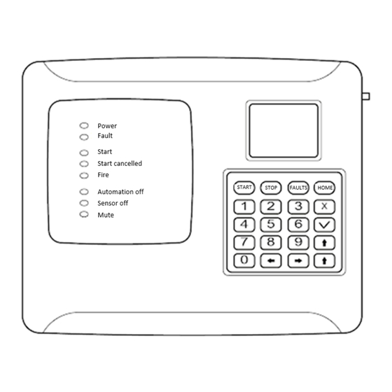
Page 19: Description Of Indicator Lights
Connect the 220V valve supply line, in accordance with the marking, according to figure 8. Primary requirements: • cable lines must be made with fire- resistant cables with copper conductors that do not spread combustion when laid in groups with low smoke and gas emission (LSFR) or halogen-free (HFFR);... -
Page 20: Application Of Mounting Devices
Table 5 - Description of light indicators Indicator Glow color CP status – constant glow - the voltage from the main power source is normal, Power green – blinks if any power supply is abnormal or an event is active that generates the «Power Standby» state –... -
Page 21: Setting The Date And Time
The following navigation buttons are used to navigate the CP menu: Governing bodies Button assignment [ ← ] [ → ] or [ ↑ ] [ ↓ ] transition between menu items selection / entry into the menu item, confirmation of the action (OK [ v ] button) [ x ]... -
Page 22: Customizing Access Levels Options And Input Patterns
CP access levels and click OK to save the data. ATTENTION! In case of loss of the pin- code, it is necessary to contact the technical support of the «Rubetek» company. ATTENTION! After carrying out the commissioning, it is necessary to replace the factory PIN code in order to exclude the possibility of hacking the system by third parties. -
Page 23: Screen Settings
2.5.5. Screen settings Open the CP menu on the CP screen by pressing the «X» button on the keyboard. Select item 6.Display press the OK button. In the menu that opens, select screen Backlight time. Press the OK button. Enter values in the range from 5 to 60 seconds. -
Page 24: Setting The Received Events And Reactions From Other Sc And Groups In The Local Network
To set up a group of devices in the network, select item 3.Group in network of the menu Network. Press the OK button. Enter the group number. Press the OK button. The system has 16 groups. Number interval from 0 to 15. ATTENTION! Setting up groups of devices is necessary for setting up events in the system, as well as scheduling and dividing the system. - Page 25 Select the required reaction point 5.Fire 1 from groups, 6.Fire 2 from groups or 7.Faults from groups. Press the OK button. In the list that opens, set the groups from which the corresponding reactions to the device will come. Items are activated with arrows ← → on the CP access levels. Press the OK button to save the changes.
-
Page 26: Setting Up Lan Protection
button. 2.5.8. Setting up LAN protection Open the CP menu on the CP screen by pressing the «X» button on the keyboard. Select item 1.Network configuration and press the OK button. Select item 11.Network protection and press the OK button. The 2.Configure devices menu sets the network key to non-secure devices (those with key=0). -
Page 27: Setting The Received Events And Reactions From Other Control Panels And Groups In The Can Network
Open the CP menu on the CP screen by pressing the «X» button on the keyboard. Select item 2.CAN configuration and press the OK button. Select 1. Ports disabling and click OK. In the list that opens, select the ports that will be inactive. -
Page 28: Control Of Fa Devices With Cp
The prefix FOREING displays events and reactions that are formed outside of this device, but affect its state and processing of these events and reactions. ATTENTION! For the correct operation of the system and management of events and reactions coming from neighboring devices, it is necessary to set the network address and the group in accordance with clause 2.5.9 of this manual. -
Page 29: Viewing The Parameters Of The Cp
ATTENTION! For devices connected via the RS-485, the network name, (IP address) and the number of faults on that network are displayed. For devices connected directly, the CAN network address range, the number of devices and the number of faults are displayed. Select the required Device. - Page 30 Viewing UPS configuration Select item 6.UPS from the Information menu. Press the OK button. This menu displays: ● Main supply- main power supply voltage; ● Backup supply- backup power supply voltage; ● Valves supply- power status (normal, fault). Viewing input/output parameters Select item 7.
-
Page 31: Sound And Display Settings
2.6.3. Sound and display settings Open the Fire Alarm Network menu on the CP screen by pressing the «V» button on the keyboard. Select item 1.Browse network and press the OK button. Select the required CP. Press the OK button. To set up the sound signaling of the CP, select the main menu item 8.Sound. -
Page 32: Setting The Input Resistance Control
- Select item 2.Configuration of the main menu. Press the OK button. - Then select item 2.UPS and press the OK button. In the list of configuration that opens, we have access to: ● Min.voltage- lower value of the device supply voltage;... -
Page 33: Setting The Cp Name, Network Address And Group
● Break on- the value of the resistance that the system perceives as a break; ● Precision- permissible error of resistance values, measured in percent. To configure each parameter, select it and click the OK button. Set the value of the parameter. Press the OK button. 2.6.6. -
Page 34: Setting The Received Events And Reactions From Other Cp And Groups
ATTENTION! Setting up groups of devices is necessary for setting up events in the system, as well as scheduling and dividing the system. It is described in detail in paragraph 2.8.10 of this manual. 2.6.7. Setting the received events and reactions from other CP and groups It is possible to configure the interaction with other CP in the CAN network on the device. - Page 35 Select the required reaction point 5.Fire 1 from groups, 6.Fire 2 from groups or 7.Faults from groups. Press the OK button. In the list that opens, set the groups from which the corresponding reactions to the device will come. Items are activated with arrows ← → on the CP access levels. Press the OK button to save the changes.
-
Page 36: Radio Setting
button. 2.6.8. Radio setting Radio channel setting Open the Fire Alarm Network menu on the CP screen by pressing the «V» button on the keyboard. Select item 1.Browse network and press the OK button. Select the required CP. Press the OK button. -
Page 37: Setting The "Sensors Bypass" Mode
2.6.9. Setting the «sensors bypass» mode The bypass mode is used to simultaneously disable all DEVs connected to this CP. At the same time, the binding and configuration of devices is saved. Reactions of disconnected devices are not displayed on the CP and do not trigger events. «Fire1» and «Fire2» signals are transmitted from the detector, but are inactive on the CP. -
Page 38: Connecting And Configuring Radio Channel Devs
2.7.1. Connecting and configuring radio channel DEVs ATTENTION! No more than 250 radio channel devices can be added to the CP, while the total number of all DEVs connected to the CP should not exceed 250 pieces. RF fire alarm devices include detector, VA. When connecting radio channel devices, the distance between the device and the device should be no more than 10 meters. - Page 39 General configuration for wireless devices (DEVs menu) If you are making configuration for a previously linked and configured device, you must: - select item 3.DEVs and press the OK button. - select submenu 1. Devices list. Press the OK button. - select submenu 2.By number.
- Page 40 Advanced configuration for wireless devices (Device configuration menu) The following options are available in the Device configuration menu: ● Status period - time interval (from 10 to 255 sec), after which the DEVs of the communication between the DEVs and the CP will take place.
-
Page 41: Connecting And Configuring Wired Devs
DEVs connected to the CP should not exceed 250 pieces. Wired DEVs fire alarms «RUBETEK» include detector, VA, IM-1 and IO4-1. When connecting wired devices, it is necessary to take into account the maximum length of the PLC from the CP to the final sensor, which should not exceed 1200 meters. - Page 42 number. The CP automatically binds a new wired device to the first free slot. The device setup menu will open. In order to send a test to a specific device from the list of bindable devices, select the desired device and hold down «0». After that, the device will be highlighted in color and go into test mode.
- Page 43 • Device configuration - additional device settings; • Reaction configuration - setting up reactions on the device; • Send test - send the Test command to the device. • Delete - remove the device from the CP. ATTENTION! Options marked with * are not configurable and are for informational purposes only.
- Page 44 ATTENTION! List of required active reactions for SD: • Fire1 from DEV- issuing a message to the CP when the chamber is filled with smoke and saved in the archive. • Tamper- issuing a message to the CP when the case is opened with preservation in the archive.
-
Page 45: Plc Line Status
After setting all the settings, click the Cancel button. The device has been configured. Check the binding of the device to the CP. Activate the TEST mode on the device using the Send Test command from the Sensor Menu. A message about testing the sensor will appear on the CP within 3 seconds, indicating the slot to which it is bound, and the device ID. -
Page 46: Configuration Up Devs Zones
- Select the main menu item 3.DEVs and press - Select submenu item 4.Configuration press - Select item 4.Voice ann. conditions activation mode, press OK. -In the list that opens, select the necessary modes in which the sound notification will be launched. Items are activated by arrows [←... - Page 47 To enable the Fire2 signal triggering mode from one detector, you must: - select the main menu item 3.DEVs. Press the OK button. - select item 2.Device zones. Press the OK button. - select the desired Zone. Press the OK button. - select item Fire 2 by single det..
-
Page 48: Devs Deactivation
To set events generated by a Device Zones, you must: - select the main menu item 3.DEVs. Press the OK button. - select item 2.Device zones. Press the OK button. - select the desired Zone. Press the OK button. - select the appropriate item Event for..Press the OK button. -
Page 49: Evaluation Of The Parameters Of Communication With The Devs
To deactivate the device, you must: Open the Fire Alarm Network menu on the CP screen by pressing the «V» button on the keyboard. Select item 1.Browse network and press the OK button. Select the required CP. Press the OK button. - select the section of the main menu 3.DEVs. - Page 50 To view device communication settings: Open the Fire Alarm Network menu on the CP screen by pressing the «V» button on the keyboard. Select item 1.Browse network and press the OK button. Select the required CP. Press the OK button. - select the section of the main menu 3.DEVs.
-
Page 51: Connecting And Configuring Radio Extender Module Re-1
The recommended communication quality at the installation site of the radio channel device should be above -80dB. If the signal level is lower, use one of the solutions: ● reduce the distance between the radio channel device and the CP; ●... - Page 52 Open the Fire Alarm Network menu on the CP screen by pressing the «V» button on the keyboard. Select item 1.Browse network and press the OK button. Select the required CP. Press the OK button. In the main menu of the CP, select item 3.DEVs and press the OK button - select submenu item 3.
-
Page 53: Connection And Adjustment Of Valve Actuators Ff
Fire 1, Fire 2, link fault); ● Bypass mode -enable/disable bypass mode; ● Smoke sensor*- the value of the current optical density of the smoke chamber; ● Link*- time since last contact; ● PLC line*- PLC line voltage; ● LI status - current status of the PLC Built-in isolator (normal, PLS1 powered, PLS2 powered);... - Page 54 Table 6 - Communication line resistance Valve position Resistance Open 9.2 kOhm Intermediate 13.9 kOhm Closed 5.7 kOhm ATTENTION! Switching on the power supply of the drive is carried out only after it is connected and configured on the device. FORBIDDEN! Turn on the drive power with the instrument cover open.
- Page 55 Turn-on configuration contains the following items: ● Relay mode - relay operation mode (pulse, none (self-on), hold); ● L1 line check – no/line break and short/line break only line control L1; ● Turn-on time - time interval for applying voltage to L1 (for pulsed mode); ATTENTION! In the pulse mode, when the feedback resistance reaches the control value, the on-time countdown stops.
-
Page 56: Connecting And Setting The Reversing Drive
Control configuration contains the following items: ATTENTION! If the flag «And my 1st fire2» is selected for the damper, then the remaining flags will work only with an active alarm of their own «Fire 2» on the CP. If the box is not checked, then the valve will work with OR logic. -
Page 57: Connecting And Setting Up An Actuator With An Electromagnetic Lock
Reversing drive setting Select the menu Turn-on configuration. Press the OK button. Then select the desired items, click the OK button and enter the data. ● Relay mode: pulse ● L1 line check: line break and short ● Turn-on time: 55 sec ●... - Page 58 Resistor ratings: R1 - 2 W - 56 kOhm ±5% R2, R3 - 0,5 W - 8,2 kOhm ±5% Figure 11 - Wiring diagram for a drive with an electromagnetic lock Adjustment of the drive with electromagnetic detent Select the menu item Turn-on configuration. Press the OK button.
-
Page 59: Connecting And Setting Up A Spring Return Actuator
EM valves.* ● Turn-off delay: 0 sec ● Work time on fire: 0 sec After filling in all the points, press the X button. *Failure to comply with the required settings may result in malfunction of the CP. Select the menu item Work mode. Press the OK button. - Page 60 Resistor ratings: R1 - 0.5 W - 8.2 kOhm ±5% R2 - 0.5 W - 1 kOhm ±5% R3 - 0.5 W - 4.7 kOhm ±5% Figure 12b - Wiring diagram of a drive with a return spring (the spring is charged in normal mode, the drive is constantly energized) Adjustment of the actuator with a return spring (the spring is not charged in normal mode) figure 12a...
- Page 61 After filling in all the points, press the X button. Select the menu item Work mode. Press the OK button. Then select the Closed- Open mode, press the OK button. To return to the previous menu, press the X button. Select the menu item Feedback control.
-
Page 62: Connecting And Configuring Lss
Select the menu item Work mode. Press the OK button. Then select the Closed- Open mode, press the OK button. To return to the previous menu, press the X button. Select the menu item Feedback control. Press the OK button. Then select Yes, then click OK. - Page 63 ATTENTION! Connection of SM-1 is carried out in compliance with the polarity and color marking of the wires. LSS output setting Open the Fire Alarm Network menu on the CP screen by pressing the «V» button on the keyboard. Select item 1.Browse network and press the OK button.
-
Page 64: Connecting And Configuring The Rc
Select the Standby mode item. Press the OK button. Select the Mode item. Press the OK button. We select the mode of operation of the LSS. Press the OK button. Select Line check. Press the OK button. Set line control mode. Press the OK button. Select Alert time. - Page 65 Figure 15 - Scheme of connection to the RC of the device Setting up the RC device Open the Fire Alarm Network menu on the CP screen by pressing the «V» button on the keyboard. Select item 1.Browse network and press the OK button.
-
Page 66: Connecting And Configuring Freely Programmable Inputs
the OK button. 2.7.15. Connecting and configuring freely programmable inputs The device has two freely programmable inputs for connecting external equipment with RC outputs. Connection of external equipment to freely programmable inputs is carried out using SM-2 switching modules. ATTENTION! The RC of external devices is set up in accordance with the operating manuals for these devices. -
Page 67: Setting Up Events And Reactions
configured. Press the OK button. The following options are available for customization: ● Line check- resistance value in standby mode; ● «Alarm» value- resistance value in operating mode; ● Reaction- selection of the action that will take place when the RC of the connected device is triggered: - none - when triggered, an event will be launched;... -
Page 68: Event State Generation
Select Event names. Press the OK button. In the list that opens, select the desired event and click the OK button. Enter the name of the event. Press the OK button to save the data. 2.8.2. Event state generation State generation allows you to set what state of the device or system will be launched when an event occurs on the device. -
Page 69: Setting Local Events
To set up an event capture, you need to: - Select item 4.Events and reactions of the main menu. Press the OK button. - Select item 6.Events configuration. Press the OK button. Select the item Fix during the fire. Press the OK button. -
Page 70: Setting An Event From The Mcp (Y,O,G)
2.8.5. Setting an event from the MCP (Y,O,G) To set the generation of an event from the MCP (Y,O,G) you must: -open the Fire Alarm Network menu on the CP screen by pressing the «V» button on the keyboard. -select item 1.Browse network and press the OK button. -
Page 71: Setting An Event To Enable The Valve Actuator
OK button. - Select the main menu item 2.Configuration. Press the OK button. - Select item 3. Inputs / outputs. Press the OK button. We select the required output of the LSS. Press the OK button. Select the item in section 1.Conditions. Press the OK button. -
Page 72: Setting An Event To Activate The Rc
- Select the main menu item 2.Configuration. Press the OK button. - Select item 4.Valves. Press the OK button. Select the desired valve. Press the OK button. Select the menu item 4.Control configuration and press the OK button. Select the item in section 1.Conditions. Press the OK button. -
Page 73: Logical Assemblies
In the list that opens, select the required Output «RC 1». Press the OK button. Select item 1.Event number. Press the OK button. Enter the number of the event that will activate the RC. Press the OK button. 2.8.9. Logical assemblies Logical assemblies are designed to create new events in the system based on existing ones, using logical operations. - Page 74 will work; ● Activation delay- time to delay the operation of the assembly; ● Deactivation delay- time to delay assembly shutdown; ● Event generation- an event that will be generated when all configured conditions are met. Select Instruction. Press the OK button. The following logical operations are available in the list that appears: ●...
-
Page 75: View Active Events
We select the item Deactivation delay of the menu Logical block. Press the OK button. Set the delay time for turning off the logical assembly. Press the OK button. Select the Event generation item of the Logical block menu. Press the OK button. Enter the number of the event that will be generated when all configured conditions are met. -
Page 76: Setting The Event For The Signal "1St Fire 2
OK button. - Select the main menu item 4.Events and reactions. Press the OK button. - Select the submenu item 5.Used events. Press the OK button. In the list that opens, events that are already used in the system are marked in red. After checking the list of events, press the Home button to return to the main menu. -
Page 77: Firefighting Setting On The Device
2.8.13. Firefighting setting on the device To set up fire extinguishing on the device, you must: -open the Fire Alarm Network menu on the CP screen by pressing the «V» button on the keyboard. - Select item 1.Browse network and press the OK button. - Page 78 IM-1. Signal 2 is generated by devices: IO4-1, IM-1. The opening sensor in systems with CP-1 is not used, then which signal the device will generate depends on the setting of the CP reactions to this device. Thus, each of the four IO4-1 inputs and the IM-1 input can be configured to generate both Signal 1 and Signal 2 at the same time.
-
Page 79: Manual Start And Shutdown Of Fire Extinguishing
- Fault: the event with the specified number is activated if any of the DEVs used to activate or block the direction of the FF is in a fault state. Deactivated, respectively, when troubleshooting. In this case, the malfunction does not affect the operation of the FF direction in any way. -
Page 80: Configuring Manual Disable Ports
Select 2.Clear to reset system faults. Press OK. In the menu that opens, select Yes to reset. Press Select 3.Test to test system fault generation. Press OK. In the menu that opens, select Yes to start testing. Records of system failures will be archived. 2.8.16. -
Page 81: Setting Access Levels
2.8.17. Setting access levels Open the CP menu on the CP screen by pressing the «X» button on the keyboard. Select item 4.Access levels press the OK button. Settings are available in three levels: - staff – at this access level, the following functions can be performed: •... -
Page 82: Viewing Fire Alarm Network Settings
ATTENTION! In case of loss of the pin-code, it is necessary to contact the technical support of Rubetek. 2.9. Viewing fire alarm network settings ATTENTION! To view the parameters and manage the fire alarm, you must go to the Fire Alarm Network menu. -
Page 83: Alarm Causes
2.9.3. Alarm causes Alarm causes contain a list of sources/causes of the «Fire-1» or «Fire-2» signal. To view a list of alarm causes: - Select item 3. Alarm causes of the fire alarm menu. Press OK. The list that opens displays the name of the main device on which the signal is activated and its address in the CAN network (#X). -
Page 84: Software Update
Show configuration in the WiFi connection menu. Next, you need to run the «Rubetek-Engineer» program on the PC and select the «Authorization» section in the left part of the window, where in the «Connection» block enter the IP address 192.168.4.1 and click the Connect button (Fig. - Page 85 Figure 17 - Connecting to the CP Next, you need to go to the «beta» section (CP firmware). Press the Select button and in the Explorer window that opens, specify the path to the required firmware file (0x10000.bin). After the file is displayed in the line, click the Update via WiFi button, as shown in fig.
-
Page 86: Cloning Of Cp Software Via Can Interface
Figure 19 - Selection of the updated CP The firmware process will begin, which will be displayed as a progress bar (Fig. 20). Figure 20 - Software update process If the firmware is successfully completed, a corresponding message will appear, after which the CP will restart. - Page 87 To clone the device software to other devices connected via the CAN bus, you must: -open the Fire Alarm Network menu on the CP screen by pressing the «V» button on the keyboard. - Select item 1.Browse network and press the OK button.
-
Page 88: Software Update On Devs
The software update time for one sensor is no more than 30 sec. 2.13. Uploading a CP dump ATTENTION! The dump is unloaded only from the CP. Logging is performed only from the CP in the remote mode. To connect to the CP you need: - Software «Rubetek-Engineer»;... -
Page 89: Maintenance
ATTENTION! All software can be downloaded from the official website of «RUBETEK». To remove the dump, you need (figure 21): ● run the software program «Rubetek-Engineer» on the PC and go to the config section; ● specify the necessary data for unloading the dump in the Settings block;... -
Page 90: Health Check
3.1.5. To ensure safety during the operation of the device, it is prohibited: - to carry out any work with the device with the connected voltage AC 220 V and DC 24 V; - operate the device with damaged wire insulation. 3.2. -
Page 91: Control Run Of Lss, Valve Actuator Ff
The indication of the device must correspond to the status of «Norm» and «Power» according to table 5. 3.2.4. Control run of LSS, valve actuator FF Enabling manual control To set the manual mode on the device, you must: In the Main menu of the device, select item 7.Mode and press OK. -
Page 92: Viewing The Factory Number Of The Cp
To check the version of the device, select item 13. Build version of the CP menu. ATTENTION! The current version can be found in the technical support service of the company «RUBETEK». 3.2.7. Viewing the event archive To view the event archive: - select item Main menu 6.Archive. -
Page 93: Alert Test
«0» button. ATTENTION! In case of loss of the pin-code, it is necessary to contact the technical support of «Rubetek». After that, records of the selected events will be recorded in the archive. To view these records in a separate section, select item 6.Archive of the... -
Page 94: Storage
Storage 4.1. The storage conditions of the CP must comply with conditions: – ambient air temperature from plus 5 °С to plus 40 °С; – relative air humidity up to 80% at a temperature of plus 25 °С. 4.2. The device should be stored on racks in a packaged form. 4.3. -
Page 95: Information About Complaints
Standards compliance 9.1. Addressable fire alarm control panel CP-1-(X) «RUBETEK» complies with the European standard EN 54-2 «Fire detection and fire alarm systems. Part 2: Control and indicating equipment » and EN 54-25 «Fire detection and fire alarm systems. Part 25: Components using radio links».
Need help?
Do you have a question about the CP-1 and is the answer not in the manual?
Questions and answers