
Summary of Contents for RUBETEK SC-1
- Page 1 MANUAL SYSTEM CONTROLLER SC-1 «RUBETEK» Complies with: EN 54-18 Hardware version: rev.3 Software version: 2022-12-1 Document version: 2022-12-1...
-
Page 2: Table Of Contents
Table of contents Introduction ..............................4 Description and operation ......................5 1.1. Function ............................5 1.2. Technical data..........................5 1.3. Controller location ........................6 1.4. Appearance of the controller ......................6 1.5. Internal design of the controller ....................6 1.6. Complete set .......................... - Page 3 2.8.4. Fixing events during the fire ...................... 39 2.8.5. Local events configuration ......................39 2.8.6. Configuration of event generation from DEVs ................40 2.8.7. Configuration of event to enable LSS ..................41 2.8.8. Configuration of event for RC activation ................... 41 2.8.9.
-
Page 4: Introduction
Installation and operation of the controller must be carried out by technical personnel after reading this Manual. List of abbreviations used: − CC - control cabinet; − CP - addressable fire alarm control panel CP-1-(Х) «RUBETEK»; − CW - commissioning works; − DEVs - alarm and notification devices; − FA - fire alarm;... -
Page 5: Description And Operation
«RUBETEK» System Controller SC-1 (hereinafter Controller) is designed for centralized protection of buildings and structures from fires. Controller is connected to «RUBETEK» CP-1 (hereinafter СP) and operates as part of «RUBETEK» system of wired and radio automatic fire alarm. The device provides: ‒... -
Page 6: Controller Location
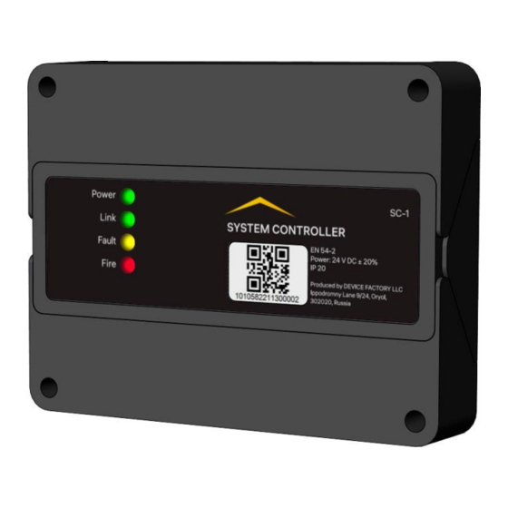
1.3. Controller location Figure 1 – Location of SC in the system 1.4. Appearance of the controller 1 – Case 2 – LED indicators 3 – Controller serial number (QR-code) 4 – Cover fixing holes Figure 2 – Device appearance 1.5. - Page 7 1 – Input of the main and backup power; 2 – Freely programmable IN1, IN2 inputs; 3 – Power line communication PLC1, PLC2; 4 –RS-485 interface; 5 – Acoustic source; 6 – Tamper sensors; 7 – «Power» indicator; 8 – «Link» indicator; 9 –«Fault»...
-
Page 8: Complete Set
+OUT2 - VA supply positive contact Output 2 for VA connection OUT2 -OUT2 - VA supply negative contact 1.6. Complete set Table 3 – Complete set of the controller Item Quantity, pcs. Remarks System Controller SC-1 «RUBETEK» Mounting kit Datasheet Individual packing... -
Page 9: Intended Use
Intended use 2.1. Preparation for use ATTENTION! If controller was in conditions of negative temperature, keep it at least 4 hours at room temperature (25 ± 10 ºС) to prevent moisture condensation. Open the package, make sure that the completeness of the controller corresponds to table 3. Conduct visual inspection, make sure that there are no visible mechanical damages (chips, cracks, dents) and traces of moisture. -
Page 10: Connection
2.3.2 Mounting the controller on a surface: - make markings at the installation site; - drill holes with a diameter of 5 mm and a depth of 30 mm for installing dowels; - unscrew the 4 fixing screws and open the two hinged covers on the controller case to access to the mounting holes;... -
Page 11: Rs-485 Interface Connection
2.4.2. RS-485 interface connection RC-485 interface provides communication between the Controller and the CP and has a «Ring» topology. Several controllers to CP connection diagram on the example of a 5-floor section is shown in figure 7. Figure 7 – Controllers to СP connection diagram It is recommended to connect the controllers to the RS1 and RS2 interfaces across the floor and use RS-485 lines between neighboring devices with a maximum length of 150 m (see Fig. - Page 12 ‒ linear capacitance between wires A and B of the interface must not exceed 60 pF/m. ATTENTION! Form and mark the wires at the connection stage. 2.4.3. Power supply line connection Connect the power supply line of the controller 24V from the main and backup (required) sources, observing the polarity according to figure 9.
-
Page 13: Controller Initial Configuration
– fault in the power supply system of the controller; – controlled lines continuity-failure; – receipt of the «Fault» signal from DEVS; Fault yellow – no link with DEVS; – opening case of the controller and so on. «Fire» signal received from the detector, from the CAN Fire network or from external equipment connected to the SC inputs. -
Page 14: Setting Accepted Events And Reactions From Other Scs And Groups Of The Rs-485 Interface
ATTENTION! The name of the device allows you to identify it and is necessary for event management and analysis of device archive records. To configure a group of devices on the network, select Group in network from the Network menu. From the presented list select the group number. - Page 15 - in the list that opens, set the groups with which the controller will interact, and the group in which the SC itself is located. Items are activated using the [← →] arrows on the CP keyboard. Press Ok to save changes. Configuration of the groups from which Fire 1, Fire 2, Fault alarm signals are received To configure the groups from which alarm signals are received, to select Fire 1 from groups, Fire 2...
-
Page 16: Configuration Of Controller Using Cp-1
Setting the response time from the control panel The time during which the SC will respond to previously sent events from the neighboring SC with which communication was lost. To set the interaction time, you must select item 10. Link timeout. Press the OK button. Set the time in the range from 0 to 255. -
Page 17: Supply Voltage Control Configuration
ATTENTION! When conducting CW, it is recommended to turn off the sound alarm of the controller. ATTENTION! Turning off the sound alarm of the controller does not turn off LSS. 2.6.2. Supply voltage control configuration Supply voltage control may be set on the controller. For this: - Select 2.Configuration in the main menu. -
Page 18: Rf Сonfiguration
Select 6.Resistance inputs. Press Ok. In the list that opens the following configurations are available: ● Short on - resistance value, which the system perceives as a short circuit; ● Break on - resistance value, which the system perceives as a break; ●... -
Page 19: Sensors Bypass" Mode Configuration
DEVs connected to the SC must not exceed 250 pieces. The «RUBETEK» Fire Alarm wired DEVs are SD, MCP, HD, VA, IM-1 and IO4-1. When connecting wired devices, you must take into account the maximum length of the PLC from the SC to the end sensor, which should not exceed 1200 meters. - Page 20 Before connecting a wired device, prepare and make sure that it operates according to the user manual for this device. ATTENTION! Before pairing devices, all PLC lines and installation of wired DEVs and SC bases must be completed. In the main menu select 3.DEVs and Press Ok. - select 3.Device pairing submenu.
- Page 21 The following parameters are available in the list that opens: ● Name - device name; ● Zone - allows you to group the devices of one fire zone. The SC has 32 zones; ● Device type* - determined automatically; ● Status*- current status of the device (normal, Fire 1, Fire 2, no link);...
- Page 22 To enter values, select the required menu item. Press Ok. Enter the value. Press Ok to save. After entering all the values, press Ok and go to Reaction configurations. ATTENTION! All configurations in this section are stored in the extender memory. Wired device reactions configuration (Configuration reactions menu) ATTENTION! List of required active reactions for SD: ●...
-
Page 23: Re-Plc (Re-1) Connection And Configuration
ATTENTION! List of required active reactions for IM-1: ● Fire 1 from DEV - with the resistance of the communication line, which corresponds to the Warning mode, the Fire1 signal will be triggered; ● Fire 2 from DEV - with the resistance of the communication line, which corresponds to the Alarm mode, the Fire2 signal will be triggered;... - Page 24 -Connect the PLC interface wires to the corresponding SC terminals. ATTENTION! Select the direction of the antenna, taking into account the recommendations of the user manual for the radio extender module. ATTENTION! Power supply line device «+24V» is disconnected first and connected last. Device configuration If configurations are made for a previously linked and configured device, then:...
-
Page 25: Radio Devs Connection And Configuration
ATTENTION! The total number of all DEVs connected to the Controller must not exceed 250 pieces. «RUBETEK» Fire Alarm RF devices include detector, VA. When connecting radio devices, the distance between the controller and the device must be max 10 meters. - Page 26 Enter DEVS in programming mode, for this: - open the device case; - set the switch on the PROG board to the ON state (for MCPW, SDW, HDW, MCPW (Y,O,G)). The CP will display the serial number and the time since the device was last detected. If the time is more than 5 seconds, then the device is most likely out of pairing mode.
- Page 27 ATTENTION! Options marked with * are not configurable and are for informational purposes only. Device advanced configurations (Device configurations menu) The following parameters are available in the device configurations menu: ● Status period - time interval (from 10 to 255 s) after which the DEVS communication with the SC will be polled.
-
Page 28: Plc Line Status
After setting all configurations, press Cancel. At the end of the device pairing, turn the PROG switch to the OFF state. Close device case. Check device pairing to SC by pressing the TEST button on the detector. A message about testing the sensor will appear on the CP within 3 seconds, indicating the slot to which it is paired, and the ID (name) of the device. -
Page 29: Devs Zones Configuration
2.7.6. DEVS zones configuration SC provides the ability to zone DEVS into zones and advanced configurations for the selected zone. ATTENTION! All DEVS are automatically assigned a Default zone unless another zone has been set manually. Configuration of «Fire 2» signal activation from one detector To turn on the mode of «Fire 2»... -
Page 30: Devs Deactivation
Configuration of generated events by zone To configure generated events by device zone: - select 3.DEVs in the main menu. Press Ok. - select 2.Device zone. Press Ok. - select the right Zone. Press Ok. - select the right item Event for..Press Ok. - set the number of generated event. -
Page 31: Devs Link Assessment
- select the required device. Press Ok. - select Bypass mode. Press Ok. - set bypass. Press Ok to save changes. To activate the device set the value to no. To view the list of deactivated DEVS on SC: - select 1.Information in the main menu. Press Ok. - select 5.Bypassed DEV list. -
Page 32: Lss Connection And Configuration
It displays the link parameters of the SC with the device: - Т: time since last link; - Н: identity code of the device to which the link is made (0-to SC, 1-15 number of extender linked); - Q: link quality level for RF-devices (SC-device / SC or RE device). The signal level can vary from -109 to +15 dB. - Page 33 Figure 11 – LSS connection diagram ATTENTION! Connection of VA with a total current consumption of more than 0.45 A per channel is not allowed. The connection of the switching module SM-1 to the VA is shown in figure 12. Figure 12 –...
- Page 34 LSS configurations include: ● Conditions - reactions of the system, which will turn on VA (logical OR); ● Event number – event at which LSS is activated; ● Standby mode – VA configurations by standby mode; ● Alarm mode - VA configurations when set reactions are triggered;...
-
Page 35: Rc Connection And Configuration
2.7.10. RC connection and configuration External equipment to RC device сonnection diagram of is shown in figure 13. Figure 13 – Device to RC connection diagram ATTENTION! Cable lines must be made with using fire-resistant cables with copper cores, flame retardant for group laying, low-smoke fire-resistant (LSFR) or halogen-free (HFFR). -
Page 36: Connection And Configuration Of Freely Programmable Inputs
After selecting the configured RC, set the reactions at which the activation will occur. Menu items are selected using the ←→ buttons on the keyboard. After setting all parameters press Ok. ATTENTION! Logical OR applies to selected reactions. To set RC inversion, select 3.Relay inversion. Press Ok. -
Page 37: Configuration Events And Reactions Using Cp-1
Configuration of freely programmable inputs To configure inputs select 2.Configuration in the main menu. Press Ok. Then select 3. Inputs/outputs. Press Ok. In the menu that opens select 1.Input 1 or 2.Input 2 depending on configured input. Press The following parameters are available for configuration: ●... -
Page 38: Setting Up Event Inputs
Select Event names. Press Ok. In the list that opens, select the required event and press Ok. Enter the event name. Press Ok to save data. 2.8.2. Setting up event inputs The event input setting allows you to set events that will operate with a fixed resistance at a specific input. -
Page 39: State Generation By Event
2.8.3. State generation by event State generation allows you to set which device or system state will be activated when an event occurs on the device. To set state generation: - Select 4.Events and reactions in the main menu. Press Ok. - Select 6.Events configuration. -
Page 40: Configuration Of Event Generation From Devs
- select the right event using ←↑→↓. Press «1» if you want to activate the selection and «0» to remove the activation. Press Ok to save. 2.8.6. Configuration of event generation from DEVs To configure event generation from DEVs: - select 3.DEVs in the main menu. Press Ok. - select 1.Devices list. -
Page 41: Configuration Of Event To Enable Lss
2.8.7. Configuration of event to enable LSS To activate the LSS output by event do the following: - Select 2.Configuration in the main menu. Press - Select 3.Inputs/outputs. Press Select the required LSS output. Press Ok. Select 1.Conditions. Press Ok. Activate the My fire and Foreign fire modes by →... -
Page 42: Logical Blocks
In the list that opens, select the required Output RC. Press Ok. In configurations select 1.Event number. Press Enter event number, which will actuate RC. Press Ok. 2.8.9. Logical blocks Logical blocks are designed to create new events in the system based on existing ones, using logical instructions. - Page 43 Select Instruction. Press Ok. The following logical instructions are available in the list that opens: ● AND - block is executed when all selected events have been triggered; ● OR - block is executed when at least one selected event has been triggered; ●...
-
Page 44: Active Events Information
Select Event generation menu Logical block. Press Ok. Enter the event number that will be generated when all configured conditions are met. Press Ok. 2.8.10. Active events information To view the active events: - Select 4.Events and reactions in the main menu. -
Page 45: Setting The Date And Time
9.Factory number assembly version. 2.8.15. Checking the device software version To check the version of the SC, select item 10. Build version of the main menu. ATTENTION! The current version can be found in the technical support service of the company «RUBETEK». -
Page 46: Viewing The Event Archive
«0» button. ATTENTION! In case of loss of the pin-code, it is necessary to contact the technical support of «Rubetek». After that, records of the selected events will be recorded in the archive. To view these records in a separate section, select item 5.Archive of the... -
Page 47: Software Update
ATTENTION! To update the controller software, Wi-Fi must be enabled. To update the software you will need: - PC with Wi-Fi adapter; - Software «Rubetek-Engineer». ATTENTION! All the necessary software can be downloaded on the official website of the RUBETEK company. - Page 48 Next, you need to run the «Rubetek-Engineer» program on the PC and select the «Authorization» section in the left part of the window, where in the «Connection» block enter the IP address 192.168.4.1 and click the Connect button (Fig. 15). If the connection is successful, the device will appear in the list on the right and the button name will change to «Disconnect».
- Page 49 Figure 16 – Selecting the software file Next, you need to select the SC on which the software will be updated. After selecting the device, click the Select button (Fig. 17). Figure 17 – Selection of the updated SC The firmware process will begin, which will be displayed as a progress bar (Fig. 18).
-
Page 50: Cloning The Controller Software
Figure 18 – Software update process If the firmware is successfully completed, a corresponding message will appear, after which the SC will restart. With further work in the SC menu of the control panel, the software version will change in paragraph 10.Build version. 2.10. -
Page 51: Maintenance
The CP screen will display the number of SC that are ready for software cloning. The SC-Master will display information about the download process. The SC-Slave will display information about the download process. After a successful firmware update using the cloning method, the SC-Slave will restart and an error message will appear about reading temporary parameters. -
Page 52: Functional Test
carry out any work with the device with the connected voltage AC 220 V and DC 24 V; operate the device with damaged wire insulation. 3.2. Functional test Device functional test should be carried out during scheduled or other functional checks, but at least once every 6 months. -
Page 53: Device Information
This menu contains information about the status of the device and devices connected to it. To view information, select 1.Information. Press the OK button. This menu contains the following items: ● Active alarms - list of FA devices from which the signal «Fire-1» or «Fire-2» is received;... -
Page 54: Test Run Lss
*for LSS only. ● Feedback - actual resistance value of the link in the current input/output status. ATTENTION! For LSS outputs, when the «Manual» mode is active on the device, the Command menu item is active, which allows you to start / stop the LSS. 3.2.5. -
Page 55: Storage
The notification test will be started, checking the indication and sound of the SC and CP, as well as the audible notification of the VA. Storage 4.1. Store the device on racks in a packaged form. 4.2. The distance from the walls and floor of the storage to the device packages must be at least 0.1 m. -
Page 56: Claims
A copy of the payment document for the device must be attached to the act. Certification 9.1. System controller SC-1 «RUBETEK» complies with the European standard EN 54-18 «Fire detection and fire alarm systems. Part 18: Input/output devise». Manufacturer 10.1. Name of the manufacturer’s organization: DEVICE FACTORY L.L.C 10.2.
Need help?
Do you have a question about the SC-1 and is the answer not in the manual?
Questions and answers