
Related Manuals for Solta Medical CLEAR Plus BRILLIANT

Summary of Contents for Solta Medical CLEAR Plus BRILLIANT
- Page 1 Solta C+B Service Manual CLEAR + BRILLIANT™ Laser System Service Manual 30469 Rev E Page 1...
- Page 2 Solta Medical, CLEAR + BRILLIANT and Intelligent Optical Tracking are trademarks or registered trademarks of Solta Medical, Inc. or its subsidiaries in the United States and other countries. Other names and brands may be claimed as the property of others.
-
Page 3: Table Of Contents
Solta C+B Service Manual Table of Contents CLEAR + BRILLIANT LASER SYSTEM OVERVIEW ................4 FEATURES OF THE CLEAR + BRILLIANT LASER SYSTEM ..............5 COMPUTER INTERFACE AND SOFTWARE INSTALLATION ............... 11 ASSEMBLIES ..........................17 REPLACEABLE ASSEMBLIES ......................21 PATTERN PREVIEW TEST ....................... 46 LASER CALIBRATION ........................ -
Page 4: Clear + Brilliant Laser System Overview
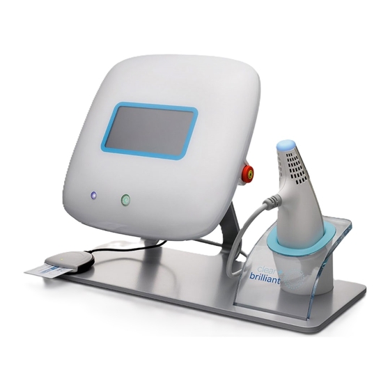
CLEAR + BRILLIANT Laser System Overview CLEAR + BRILLIANT is a non-ablative laser designed for use in dermatological procedures. This device is part of the family of Solta Medical products utilizing the Fractional Photothermolysis principle. This device consists of a Console and a base handpiece (1440 nm) with the option of purchasing additional add-on handpieces. -
Page 5: Features Of The Clear + Brilliant Laser System
Solta C+B Service Manual Features of the CLEAR + BRILLIANT Laser System The CLEAR + BRILLIANT Laser System has a laser source in the handpiece. The console is electrically connected to the facility power source. Laser energy produced by the unit is delivered to the tissue through the handpiece. Contact with the tissue is maintained by removable, disposable contact treatment tips which attach to the handpiece. - Page 6 Solta C+B Service Manual Back View of the System Console The back view of the system includes: • Power Input: A power cord connects the system to the electrical outlet. The power input on the back of the console is a standard IEC60320 type C14 male connector (within the U.S.), or a hospital grade, grounded power cord.
- Page 7 Solta C+B Service Manual • Fuse: To remove and/or install the replaceable fuse in the back panel of the system console, press on the center tab to release the fuse enclosure, pull up gently and replace the fuse. Place the new fuse back into the pocket until is snaps into place.
- Page 8 Solta C+B Service Manual Handpiece with Treatment Tip The handpiece delivers the laser energy to the surface of the skin through the laser aperture, only if the required treatment tip is in place. The activation and selector buttons (for low, medium, or high treatment settings) and light indicators can be found on the top side of the handpiece.
- Page 9 Solta C+B Service Manual System with Extender Cable The handpiece connector connects the handpiece and handpiece cable to the system console. The cable plugs into the connector. Optionally the Handpiece Extension Cable (PN 44863, Cable, Assembly, Handpiece, Extension, C+B) can plug into this connector so that the connection and be more easily accessed when interchanging the...
- Page 10 Solta C+B Service Manual 30469 Rev E Page 10...
-
Page 11: Computer Interface And Software Installation
Solta C+B Service Manual Computer Interface and Software installation This section of the service manual contains instructions on interfacing a computer using a terminal program to the system. In addition, the system operates certain software and firmware versions that may have to be installed in the event of a service work order. - Page 12 Solta C+B Service Manual 3.2.5 Select “setup”, then “window”. 3.2.6 Enter the following settings. 3.2.7 Select “setup”, then “terminal”. 3.2.8 Then enter the following settings. 3.2.9 Tera Term is ready for communication with the Clear & Brilliant. 30469 Rev E Page 12...
- Page 13 Software Upgrades using a USB Memory Stick. 3.3.1 Obtain a USB memory stick with currently released software upgrade files from Solta Medical. Format the memory stick using file system FAT32. 3.3.2 Load the software files onto the memory stick and insert into one of the two USB ports of the system.
- Page 14 Solta C+B Service Manual 3.4.3 Setup the correct hardware component; USB Blaster. 3.4.4 Select the appropriate check marks as seen in the picture above. 3.4.5 Open the system’s console to expose the back panel. See instructions in the assembly section for guidance on opening the system.
- Page 15 Solta C+B Service Manual 3.4.8 Turn on the power to the system 3.4.9 Click Start on the programmer. 3.4.10 Wait for the message, “Successfully performed operation”. 3.4.11 Turn off power to the system. 3.4.12 Disconnect test cables. 3.4.13 Switch S1 to OFF (slide switch from outside to inside toward center of system).
- Page 16 Solta C+B Service Manual Step 3.5.2 Step 3.5.3 30469 Rev E Page 16...
-
Page 17: Assemblies
Solta C+B Service Manual Assemblies CONSOLE – Mechanical and Parts List. Version 1.0 and Version 1.5 The Version 1.0 console will have a s/n that begins with BC and the Version 1.5 console will have a s/n that begins with FC. CB-CONSOLE Version 1.0 and Version 1.5. - Page 18 Solta C+B Service Manual 43049 CABLE, LINE OUT TO AUDIO AMP 43053 CABLE, USB, INTERNAL V 1.0 Console P011925-01 CABLE ASSEMBLY, USB INTERNAL V 1.5 Console 43063 DISPLAY, TFT-LCD V 1.0 Console P013360-01 FRU, REPLACEMENT LCD, C+B 1.5 V 1.5 Console 43064 SPEAKER, 8 OHM, 2W, 86DB, 70X30.5MM V 1.0 Console...
- Page 19 Solta C+B Service Manual HANDPIECE – Mechanical and Parts List 30469 Rev E Page 19...
- Page 20 Solta C+B Service Manual CB-HANDPIECE or CB-HP-1440 Description Find 9, 10, P08259-01 FRU, C+B 1440 HANDPIECE SNOUT 11, 12 03-00538 Screw, Socket Cap, 2-56 X 1/4", STNLS 10402 ASSY, LOWER HOUSINGS AND CABLE 42994 OUTER HOUSING, HANDPIECE, LOWER, LEFT 42995 OUTER HOUSING, HANDPIECE, LOWER, RIGHT 43145 WIREFORM, LOWER HOUSING ATTACHMENT...
-
Page 21: Replaceable Assemblies
Solta C+B Service Manual Replaceable Assemblies CB-CONSOLE - Covers 5.1.1 Rear Bezel (43005) - Remove the qty. 7 screws as seen below. The two screws circled below are different lengths and must be placed back in same location during the reassembly process. 5.1.2 Rear Bezel Lower (43006) –... - Page 22 Solta C+B Service Manual 5.1.3 Front Bezel (P011493-01) – Remove the qty 4 screws followed by removing front bezel. 5.1.4 For reassembly reverse the above steps. 5.1.5 On Version 1.5 Console, when reassembling a check of the functionality of the Front Panel Button Assembly must be done to ensure the buttons are properly engaging and not getting stuck.
- Page 23 Solta C+B Service Manual LCD (43063) Version 1.0 5.2.1 Follow above Cover removal process. 5.2.2 Remove the qty. 6 screws shown below securing the Chassis Service Panel (43011). 5.2.3 Disconnect both the fan (J2) and speaker (J9) connectors from the Main Controller board (43030) and remove the panel.
- Page 24 Solta C+B Service Manual 5.2.6 If flex cable (43034) is being replaced, ensure that it is oriented with the blue tab up, and the 45-degree fold as shown. 5.2.7 Reverse the above steps for reassembly. Note: Double sided tape may need to be reapplied to the LCD brackets prior to reassembly. 5.2.8 After reassembly, confirm device passes Power On Self-Test (POST) Internal Access Version 1.0...
- Page 25 Solta C+B Service Manual 5.3.4.3 RJ45 connector (P010424-01) 5.3.4.4 Cut tie wrap (09-02772) 5.3.5 Rotate assembly up and disconnect serial cable (43316) from J7 on Motherboard. 30469 Rev E Page 25...
- Page 26 Solta C+B Service Manual 5.3.6 You should see an accessible assembly that resembles the below allowing for repair and/or replacement of internal components. Main Controller (P010607-01) Version 1.0 5.4.1 Follow the internal access process. 5.4.2 Disconnect cable connections J5, J7, J11 and J14 and remove PCA flex cable from main controller board.
- Page 27 Solta C+B Service Manual 5.4.5 After reassembly, confirm device passes Power On Self-Test (POST) and perform Power Verification, Mouse Simulation (section 8.0) Front Panel Buttons Board. (43028) Version 1.0 5.5.1 Follow the internal access process. 5.5.2 Disconnect J11 from front panel button board. 5.5.3 Remove the 2 screws securing the board to the front chassis.
- Page 28 Solta C+B Service Manual 5.7.2.1 Refer to video board replacement for proper reconnection of board. 5.7.3 Disconnect J19, J36 and audio plug from Motherboard. 5.7.4 Remove the 4 screws securing the motherboard to the front chassis. 5.7.5 Remove/replace motherboard. Note: Replacement motherboard needs BIOS pre-loaded prior to installation.
- Page 29 Solta C+B Service Manual Internal Access – Version 1.5 5.9.1 Follow the Cover removal process in section 5.1. 5.9.2 Remove the qty 13 screws securing the Rear housing internal (P011787-04). 5.9.3 Disconnect Fan connection at J16 on the E-Stop side and Fan connection at J2 along with speaker connector J9 from the main board (P011798-01).
- Page 30 Solta C+B Service Manual 5.9.4 Remove the Flex connector bracket held on by 2 screws. 5.9.5 Remove the 2 screws holding the rear chassis to the front housing, once you remove these screws the 2 pieces will be loose. You will need to hold the Rear Chassis while doing the next steps.
- Page 31 Solta C+B Service Manual 5.9.6 Disconnect Audio cable from J8 on the Main PCB, disconnect Power cable J10 on Main PCB, disconnect serial cable coming from Main PCB. 5.9.7 Disconnect the PCI cable between the Main PCB and the Mother board. 5.9.8 Slowly lift the Rear Chassis up.
- Page 32 Solta C+B Service Manual 5.9.10 Disconnect the rainbow colored Main Controller cable from the Main Controller Board. 5.9.11 Disconnect the AC power cable from the Power Supply. 30469 Rev E Page 32...
- Page 33 Solta C+B Service Manual 5.9.12 You should now be able to separate the two pieces and lay them on the bench side by side for access to replacing all parts. 5.9.13 Reverse these steps for reassembly. 5.9.14 After reassembly, confirm device passes Power On Self- Test (POST) and perform Power Verification, Mouse Simulation (section 8.0).
- Page 34 Solta C+B Service Manual 5.10.3 Flip the Rear Chassis over and remove the 2 screws shown. 5.10.4 Flip the Chassis back over and you should be able to remove the Main controller board. 30469 Rev E Page 34...
- Page 35 Solta C+B Service Manual 5.10.5 Remove the PCI ribbon cable connector and the 2 Jack screws and nuts from the old PCB and attach to the replacement Main Controller board. 5.10.6 Reverse these steps to install the replacement Main Controller board. Then Reverse the steps in Section 5.9 and 5.1 to reassemble the system.
- Page 36 Solta C+B Service Manual 5.11.3 Connect the replacement Display board and reverse the steps to install the Display Board. Then Reverse steps 5.9 and 5.1 for reassembly. 5.11.4 After reassembly, confirm device passes Power On Self- Test (POST) and perform Power Verification, Mouse Simulation (section 8.0).
- Page 37 Solta C+B Service Manual 5.12.5 With the Mother Board removed the Compact Flash card can be replaced. 5.12.6 The Mother Board can now be replaced. Reverse these steps to install the Mother Board. Then Reverse Section 5.11 and 5.9 and 5.1 for complete reassembly. 5.12.7 After reassembly, confirm device passes Power On Self- Test (POST) and perform Power Verification, Mouse Simulation (section 8.0).
- Page 38 Solta C+B Service Manual 5.13 Power Supply (P011910-01) Version 1.5 5.13.1 Complete steps 5.1, 5.9, 5.11 and 5.12 5.13.2 Once the Mother Board is removed, disconnect the connections and remove the 4 mounting screws. 5.13.3 Remove and Replace the Power Supply. See photo below for correct orientation.
- Page 39 Solta C+B Service Manual 5.14.3 Pry the LCD away from the Front Housing using a flat blade screw driver. It is secured with pressure sensitive adhesive tape. Remove the excess pad and tape material on the front housing. 5.14.4 Remove the Video ribbon cable from the back of the old LCD and attach to the back of the new LCD making sure the cable is plugged in straight.
- Page 40 Solta C+B Service Manual 5.14.7 Remove the tape backing from the back side of the Display Pad and affix to the Front Housing. 5.14.8 Carefully feed the Video cable through the front Housing and remove the 4 tape backing tabs from the front of the Display Pad.
- Page 41 Solta C+B Service Manual 5.14.10 Place the Front Housing with LCD attached into the Front Bezel and tighten down with the 4 screws removed in step 5.14.3. 5.14.11 Press both the power and Acknowledge buttons to verify that the Bezel buttons properly engage with the front panel PCA.
- Page 42 Solta C+B Service Manual 5.15 HANDPIECE – Covers 5.15.1 Snout Assembly (10403) – Remove the tip to access the qty 2 screws securing the snout to the HP inner housing. 5.15.1.1 Snout window (02-04949) is adhered to snout with G-S Hypo Cement (09-03015).
- Page 43 Solta C+B Service Manual 5.15.3 Upper Housing Assembly (10398) 5.15.3.1 If tie wraps are present securing the HP com cable (43047) to grounding bracket (43261), cut tie wraps and disconnect HP from HP controller Board. 5.15.3.2 Remove the qty 4 screws securing the board assembly (P013078-01) to upper housing.
- Page 44 Solta C+B Service Manual 5.15.3.5 Replace/repair housings. 5.15.3.6 Reverse steps for reassembly. 5.15.4 After reassembly, confirm device passes Power On Self-Test (POST) and Pattern Preview Test (Section 6.0) 5.16 PCB BOARD ASSEMBLY 5.16.1 Follow the Handpiece Cover process for snout and lower housing removal.
- Page 45 Solta C+B Service Manual Item Part # Description 43039 PCA, HANDPIECE DAUGHTER 43035 PCA, MAIN, HANDPIECE CONTROLLER 43090 PCA, HANDPIECE DC DAUGHTER 43226 SUPPORT, PCB, HP 43246 SUPPORT, SWITCH, HP-PCB 40662 TAPE, KAPTON, 3/4IN WIDE P012217-01 PCA, TREAT LED BOARD (Soldered On) 5.16.7 Reverse the steps for reassembly.
-
Page 46: Pattern Preview Test
It is important for the user to become familiar with the system’s visual and audible feedback indicators. For this purpose, Solta Medical provides “burn paper” with each box of CLEAR + BRILLIANT tips for the user to produce a pattern preview test. -
Page 47: Laser Calibration
Solta C+B Service Manual Laser Calibration Connect the Handpiece to the console to be used to test the handpiece. Connect the USB Keyboard and Mouse to the test console. Connect TeraTerm from your laptop to the serial communication port. Power on the system. Wait for the Welcome Screen. -
Page 48: Power Verification; Mouse Simulation
Solta C+B Service Manual Power Verification; Mouse Simulation Purpose is to qualify the system for proper operation after installation, service, or annual preventative maintenance. The service engineer requires a keyboard and mouse connected to the system and a laser power meter. Note: Make sure the power meter’s calibration sticker is current before use. - Page 49 Solta C+B Service Manual LASER POWER – 1440 nm Handpiece, tolerance range +/- 20% Actual Hand Expected Power Minimum Maximum Reading Treatment Speed Level (cm/s) Pass / Fail 1.60 1.28 1.92 2.24 1.79 2.69 High 2.15 1.72 2.58 0.42 0.33 0.50 0.58 0.47...
-
Page 50: Error Codes And Troubleshooting
Solta C+B Service Manual Error Codes and Troubleshooting Error code list Error Error Name Error Meaning Code HandPieceCalibrationInfoError, Handpiece calibration info bad or missing CollimatorCalibrationInfoError, Collimator calibration info bad or missing SelfTestTaskCreationError, Cannot create self-test subtask NoFpgaDriver, Bad or missing FPGA driver FpgaAccessFailed, FPGA access failed Console/Handpiece commo pattern... - Page 51 Solta C+B Service Manual Error Error Name Error Meaning Code Sysman init failed to get self-test SysmanInitFailedGetSelfTestMsgQ, message queue Sysman init failed to find motherboard ID SysmanInitFailedNoMotherboadID, Sysman init: error setting up ES manager SysmanInitErrorSetESManager, service HandswitchIsBad, Handswitch has failed ErrorSavingToFile, Error saving to file InterlockOpenDuringSelfTest,...
- Page 52 Solta C+B Service Manual Error Error Name Error Meaning Code Invalid treatment parameter in InvalidTreatmentParameter, treatment screen SwitchWavelengthFailed, Error switching laser wavelength SetEsManFireFacetsPartialFailed, Set esManFireFacetsPartial failed MainBoardMemoryChipError, Main board memory chip setup failure MotorAccessError, Error accessing motor driver SetCurrentFailure, Set Current call failed GetTemperatureFailure, Calculate laser temperature failed CalibrationTemperatureUnstable,...
- Page 53 Solta C+B Service Manual The wrong card might have been inserted for the connected handpiece. Verify card matches connected handpiece. Insert correct card into reader. All treatment credits have been used up. Insert a SmartCard with available treatment credits. Handpiece temperature must not exceed 40°C.
- Page 54 Solta C+B Service Manual Turn the system off and restart after 10 seconds. If the system is still not functioning, please contact Customer Service. This message not specific to Error: 139. This is just one example for various Error codes. If you’d like to power system OFF, press the ON/OFF button to...
- Page 55 Solta C+B Service Manual Troubleshooting Issue Troubleshooting steps Handpiece Skipping, Tracking Fogging can interfere with the Permea 1927 tracking, and or Not Firing cause skipping, tracking or not firing issues. This can be caused by evaporated water from the skin condensing on the tip or water vapor within the tip interfering with the optical tracking mechanism of the laser.
- Page 56 Solta C+B Service Manual Issue Troubleshooting steps Error 129 If you remove a HP with the Power On it that could affect the calibration data (Energy table) which is stored in the hand piece on the U5 (1wire EEROM memory). This table is constructed during the calibration process.
- Page 57 Solta C+B Service Manual Issue Troubleshooting steps The customer has either 40 1. Verify the correct card is being used with the correct minutes OR 800 sq cm Handpiece. (Permea - Blue HP / 1440 - White HP) Perméa coverage, not both. card displays the word Permea under the word Brilliant on If the customer feels they are the card.
-
Page 58: Clear + Brilliant Laser System Specifications
Solta C+B Service Manual 10.0 CLEAR + BRILLIANT Laser System Specifications 10.1 Technical Specifications-1440nm Handpiece Invisible Laser Radiation IEC 60825 Classification Class 3R 1440 ±20 nm; min:1420 max:1460 Wavelength Maximum Power (average) 2.5 W Maximum Pulse Energy 9 mJ Maximum Pulse width <... - Page 59 < 45000 feet / 13846 meters 10.6 Compatible Delivery Devices Only use original CLEAR + BRILLIANT Disposable Tips. Contact Solta Customer Service or your local authorized distributor of Solta Medical products for more information. 10.7 Electromagnetic Compatibility and Immunity This guidance and manufacturer's declaration information pertain to the...
- Page 60 Solta C+B Service Manual The CLEAR + BRILLIANT complies with applicable and required standards for electromagnetic interference: The CLEAR + BRILLIANT does not normally affect nearby equipment and devices. The CLEAR + BRILLIANT is not normally affected by nearby equipment and devices.
- Page 61 Solta C+B Service Manual voltage variations on 0°, 45°, 90°, 135°, 180°, 0°, 45°, 90°, 135°, 180°, the user of the CLEAR + BRILLIANT power supply input 225°, 270° and 315° 225°, 270° and 315° requires continued operation during power lines mains interruptions, it is recommended that the 0% UT;...
- Page 62 Solta C+B Service Manual Table 9: IEC 60601-1-2, 4 Ed, - Test specifications for ENCLOSURE PORT IMMUNITY to RF wireless communication equipment. Test Maximum Immunity Band Distance frequency Power Test Level Service Modulation (MHz) (MHz) (V/m) Pulse 380-390 TETRA 400 modulation 430-470 GMRS 460, FRS...
- Page 63 Solta C+B Service Manual 10.8 Regulatory Compliance 10.8.1 Laser Safety and Electrical Product Safety Standards CLEAR + BRILLIANT meets applicable electrical and laser safety standards (per IEC 60601 series and IEC 60825-1) for a Class 3R laser. The CLEAR + BRILLIANT Laser System contains a Class 3R laser, according to IEC/EN 60825-1:2007 standards.
-
Page 64: Labeling
Solta C+B Service Manual 11.0 Labeling The CLEAR + BRILLIANT Laser System bears the required manufacturing warning labels. The location, positioning and formatting of labels are subject to change. 30469 Rev E Page 64... - Page 65 Solta C+B Service Manual Labels on Handpieces Regulatory Compliance Labels The location, positioning and formatting of labels are subject to change 30469 Rev E Page 65...
- Page 66 Solta C+B Service Manual 30469 Rev E Page 66...
-
Page 67: Labeling Symbols
Solta C+B Service Manual 12.0 Labeling Symbols BS EN ISO 15223-1: 2012 Medical devices—Symbols to be used with medical device labels, labeling and information to be supplied. Part 1: General requirements Symbol Symbol Symbol Title Additional Information Ref. The date of manufacture, as well as the name and address of the manufacturer, can be 5.1.1 Manufacturer... - Page 68 Solta C+B Service Manual BS EN 50419:2006 Marking of electrical and electronic equipment in accordance with Article 11(2) of Directive 2002/96/EC (WEEE) Symbol Symbol Additional Information Title WEEE This product contains electrical and electronic components that may contain wheeled materials which, if disposed with general waste, could be damaging to the environment.
- Page 69 Solta C+B Service Manual IEC TR 60878 Ed. 3.0 b:2015 Graphical symbols for electrical equipment in medical practice Symbol Symbol Title Additional Information Symbol Ref. To indicate on the rating plate that the equipment is suitable for alternating current 5032 Alternating current only;...
- Page 70 Solta C+B Service Manual Other Marks and Symbols Symbol Symbol Description Additional Information On/Off (push/push) Based on IEC 60417-5009 (2002-10) Stand-By Symbol European Conformity The product conforms to European Medical Directive mark 93/42/EEC and meets applicable health, safety and environmental requirements. If the mark is accompanied Notified Body: by a number, conformity is verified by the indicated TUV Rheinland...
- Page 71 Solta C+B Service Manual Other Marks and Symbols Symbol Symbol Description Additional Information Service Key (For Service ISO 7000:0717 (2004-01) Based on Technicians Only) Clear + Brilliant Product Clear + Brilliant Registered Trademark Logo Clear + Brilliant Perméa Clear + Brilliant Registered Trademark Product Logo Clear + Brilliant Laser Clear + Brilliant (registered trademark) product name...
-
Page 72: Shipping, Installation And Set-Up Requirements
If there is exterior damage, DO NOT ACCEPT OR UNPACK THE SYSTEM. Contact Solta Product Support or your local authorized distributor of Solta Medical products and the shipping company immediately. Store the system indoors and at a temperature similar to the temperature of the facility in which it is to be installed. -
Page 73: Appendix A: Part Numbers And Replacement Parts
Solta C+B Service Manual Appendix A: Part numbers and replacement parts Single use packs (1 tip and single use Smartcard or 1 tip without Smartcard) are available for service use or for replacement at customer sites. The single use pack is compatible with both 1440 and 1927 handpieces. Description CB-Console CLEAR + BRILLIANT CONSOLE... -
Page 74: Appendix B: Clear + Brilliant Latching Extension Cable And Adapter Installation Procedure With Completion Form
Solta C+B Service Manual Appendix B: Clear + Brilliant Latching Extension Cable and Adapter Installation Procedure with Completion Form Latching Extension Cable and Adapter Installation Procedure for Clear + Brilliant ® This procedure is to guide users of the Clear + Brilliant system through installing the latching extension cable and associated handpiece adapter which will help prevent improper connection techniques. - Page 75 Solta C+B Service Manual Conceal the handpiece connector by placing the two plastic covers over the connector. Firmly press the two covers together. The covers will appropriately fit when the handpiece connector screws are completely fastened. Connect the handpiece adapter to the latching extension cable by pressing the latch to reveal the connector.
- Page 76 If the system self-test is unsuccessful, check the handpiece window for visible damage or debris. If there is no visible damage or debris, try again. If the system fails to pass the system self-test, it will not allow further treatment. Contact Solta Medical ®...
- Page 77 Purpose: Document the Installation of the Latching C+B Extension Cable Type of Update: Accessory Installation Form must be returned to: Solta Medical Product Support Fax: 510-373-7153 or scan and email to productsupport@solta.com For customers outside the USA email to ThermPSI@solta.com Account/Dr.
-
Page 78: Appendix C: 1927 Nm Handpiece
Solta C+B Service Manual Appendix C: 1927 nm Handpiece Field Level Part Number Description Replaceable Note ASSY, HANDPIECE, C+B 1927NM 4th P012489-01 Edition 03-00538 SCREW, SOCKET CAP, 2-56 X 1/4", STNLS 03-00587 SCREW, SOCKET CAP, 4-40 X .250, STNLS ASSY, INNER HOUSING AND HEAT SINK, 10518 1927 02-04951... - Page 79 Solta C+B Service Manual Field Level Part Number Description Replaceable Note 42989 BUTTON, ACTIVATION, HANDPIECE 42990 BUTTON, SETTING, HANDPIECE LIGHT PIPE, SETTING INDICATIONS, 42991 HANDPIECE LIGHT PIPE, POWER INDICATOR, 42992 HANDPIECE 10402 ASSY, LOWER HOUSINGS AND CABLE OUTER HOUSING, HANDPIECE, LOWER, 42994 LEFT OUTER HOUSING, HANDPIECE, LOWER,...
Need help?
Do you have a question about the CLEAR Plus BRILLIANT and is the answer not in the manual?
Questions and answers