Table of Contents
Advertisement
Quick Links
DOC PN: 260-0004
MODEL 113D
FLUXGATE MAGNETOMETER
USER MANUAL
DOC DESC: Model 113DUser Manual
CONTACT US
HEADQUARTERS
425 Clyde Avenue Mountain View, CA 94043
OFFICE
650.965.0500
EMAIL
info@appliedphysics.com
APPLIEDPHYSICS.COM
1
APPLIED PHYSICS SYSTEMS, INC. | APPLIEDPHYSICS.COM
SEPTMEBER 2022. REVISION: 0A
Advertisement
Table of Contents

Summary of Contents for Applied Physics Systems 113D
-
Page 1: Model 113D
DOC PN: 260-0004 DOC DESC: Model 113DUser Manual SEPTMEBER 2022. REVISION: 0A MODEL 113D FLUXGATE MAGNETOMETER USER MANUAL CONTACT US HEADQUARTERS 425 Clyde Avenue Mountain View, CA 94043 OFFICE 650.965.0500 EMAIL info@appliedphysics.com APPLIEDPHYSICS.COM APPLIED PHYSICS SYSTEMS, INC. | APPLIEDPHYSICS.COM... -
Page 2: Copyright
DOC PN: 260-0004 DOC DESC: Model 113DUser Manual SEPTMEBER 2022. REVISION: 0A COPYRIGHT Copyright 2014 - 2022 Applied Physics Systems Incorporated. All Rights Reserved. The contents of this manual may not be reprinted in part or whole without permission. The contents of this manual are subject to change without notice. -
Page 3: Table Of Contents
5 – INITIAL SETUP OF THE SYSTEM ........................10 6 – OPERATION OF SYSTEM ............................ 12 7 – MODEL 113D BINARY MODE PROTOCAL ..................... 13 8 - DESCRIPTON OF THE SYSTEM INTERAL CONSTANTS ................. 15 9 - CHANGING THE BAUD RATE ..........................16 10 - AVERAGING DATA ACQUISITIONS ...................... -
Page 4: Figures
DOC DESC: Model 113DUser Manual SEPTMEBER 2022. REVISION: 0A FIGURES Figure 1. Model 113D Magnetometer ........................ 8 Figure 2. Electrical Interface for Model 113D Sensor ................9 TABLES Table 1. System Specifications ........................... 6 Table 2. Serial IN and OUT Connections ...................... 11 Table 3. -
Page 5: Introduction
113D. For instance, if the ASCII characters for 0, S and D are sent in sequence, the 113D interprets this as a "send data" command and responds by sending over the serial interface an ASCII string representing the value of the magnetometer and temperature outputs. -
Page 6: System Specifications
The recorded data is then used to create a look up table for scale, offset and alignment corrections. This table is then downloaded into the 113D internal EEROM memory where it can be accessed by the system internal microprocessor. - Page 7 DOC DESC: Model 113DUser Manual SEPTMEBER 2022. REVISION: 0A Width/Length (PC board) 2.5” (63.5 mm) Height (PC board) 0.625” (15.88 mm) Weight 25 g Input/Output Connections Flying leads (Teflon insulated) #26 gauge >6” (152.4 mm) length APPLIED PHYSICS SYSTEMS, INC. | APPLIEDPHYSICS.COM...
-
Page 8: Mechanical Features
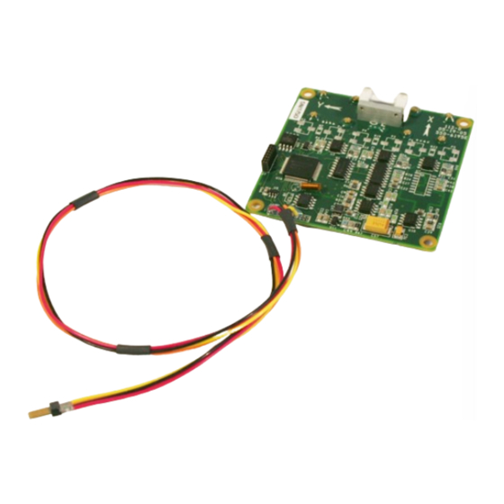
SEPTMEBER 2022. REVISION: 0A 3 - MECHANICAL FEATURES An outline drawing of the 113D System is shown in Fig. 1. The orientation of the X, Y and Z axes and the approximate location of the magnetometer sensors is also shown in Fig. 1. The output polarity sense of the axes is such that a field pointing in the direction of the arrows shown in Fig. -
Page 9: Electrical Interface
RS232 serial communications interface to the 113D is provided by the RS232-in and RS232-out lines shown in Fig. 2. An external computer talks to the 113D on the serial- in line and replies from the 113D are transmitted out on the serial-out line. The serial-in and serial-out lines are normally set to operate at 9600 baud with one stop bit and no parity. -
Page 10: Initial Setup Of The System
4.9V to 12V or optionally, from a single 4.9 to 12V supply. In order to set up a computer interface with the system, select the output protocol of the 113D. This can be either TTL or RS232. The TTL protocol is usually used in microprocessor-to-microprocessor communications. For this mode, the voltage levels for a 0 and 1 are approximately ground and 5V. -
Page 11: Table 2. Serial In And Out Connections
Serial-IN Ground Connect the Model 113D serial output line to the computer in line and the 113D serial input line to the computer serial out line. To communicate with the 113D, a terminal program will need to be run on the PC. -
Page 12: Operation Of System
The temperature (°C) follows the T header. The 113D operating characteristics are controlled by the systems internal byte constants. The 113D also has a set of internal float constants which are used to calibrate the 113 so that it produces accurate output data. Generally, the float constants correct for scale, offset and orthogonality of the magnetic field sensors. -
Page 13: Model 113D Binary Mode Protocal
When byte 35=40 data transmission in ASCII mode is slowed down to about 1 transmission per second. 7 – MODEL 113D BINARY MODE PROTOCAL Consider the following data transmissions from a 113D; one in ASCII mode and one in Binary mode ASCII MX : +0.27400... - Page 14 DOC PN: 260-0183 DOC DESC: Model 1540 User Manual JULY 2022. REVISION: 03 The status byte is currently unused. The CS byte is a checksum and is calculated by summing all of the bytes in the transmission before the CS byte excluding the SOT character. For the above transmission the checksum is calculated as follows: CS = 0A+B4+FC+1C+25+5D+08+7E+02+BC+80 = 41C The checksum is the lower byte of the sum, or 1C.
-
Page 15: Descripton Of The System Interal Constants
8 - DESCRIPTON OF THE SYSTEM INTERAL CONSTANTS The Model 113D employs two types of internal constants 1) byte and 2) floating. Byte constants are used to configure the system and floating constants are used for the system calibration. A list of the most important byte and floating constants is shown below: Table 3. -
Page 16: Changing The Baud Rate
DOC PN: 260-0183 DOC DESC: Model 1540 User Manual JULY 2022. REVISION: 03 Although float constants are not commonly used when operating the Model 113D system, a complete list of float constants are included in Table 4 for your reference. -
Page 17: Averaging Data Acquisitions
When byte constant 09 is set to any value other than 5A, the system baud rate is 9600. 10 - AVERAGING DATA ACQUISITIONS To reduce noise in noisy environments the data outputs from the 113D can be averaged. Averages of 2, 4 8, 16, 32 and 64 samples can be obtained by setting the value of byte 23 to the following values: Table 6. - Page 18 DOC PN: 260-0183 DOC DESC: Model 1540 User Manual JULY 2022. REVISION: 03 X magnetometer scale Y magnetometer scale Z magnetometer scale 13 - 21 Not Used Mag Base Ortho (X,X) Mag Base Ortho (X,Y) (Denotes X axis in the Y direction) Mag Base Ortho (X,Z) Mag Base Ortho (Y,X) Mag Base Ortho (Y,Y)
-
Page 19: Table 8. Byte Constant Numbers And Their Meanings
DOC PN: 260-0183 DOC DESC: Model 1540 User Manual JULY 2022. REVISION: 03 Table 8. Byte Constant Numbers and Their Meanings Byte Function Constant Command Echo Flag No command echo Echo enable Autostart Flag If 0x5A executes the selected autostart option on powerup No auto send enable 0x05A Auto send enable... - Page 20 DOC PN: 260-0183 DOC DESC: Model 1540 User Manual JULY 2022. REVISION: 03 2400 4800 9600 Power cycle the unit or the change in baud rate will not take effect. Average control See section 10 - AVERAGING DATA ACQUISITIONS RTS Delay, inserts a time delay between data byte transmissions...
Need help?
Do you have a question about the 113D and is the answer not in the manual?
Questions and answers