
Summary of Contents for Intelligent Appliance IA-2104-U
- Page 1 User Manual IA-2104-U 4 Relays Controlled Module Version 0113 www.intelligent-appliance.com...
- Page 2 13 Giborey Israel, Netanya 4250413, Israel Feedback We at Intelligent Appliance highly value your opinion. Please feel free to contact us with your impression on any subject, or with any question you may have. Warning Intelligent Appliance products are NOT authorized for use as components in life support devices or systems.
-
Page 3: Table Of Contents
IA-2104-U 4 Relays Controlled Module Contents Introduction............. Specifications............System Wiring............... Pin Assignment..............Software Installation............Command Set............Get Device Name............Get Device Firmware..........Get Relays Status..........Get Device Mode..........Get Device Serial Number........Get User Defined Jumper Setting......Set Relays Status.......... -
Page 4: Introduction
Controlled Module Introduction The IA-2104-U is a USB Relay controller module, powered and controlled by a USB port, it includes 4 SPDT Power Relays, with contact rating of 8 amp both at 30VDC and 240VAC. The IA-2104-U is software compatible to the Intelligent Appliance IA-3000 Series. -
Page 5: System Wiring
IA-2104-U 4 Relays Controlled Module System Wiring Host PC Type A Type B Specifications subject to change without notice. www.intelligent-appliance.com... -
Page 6: Pin Assignment
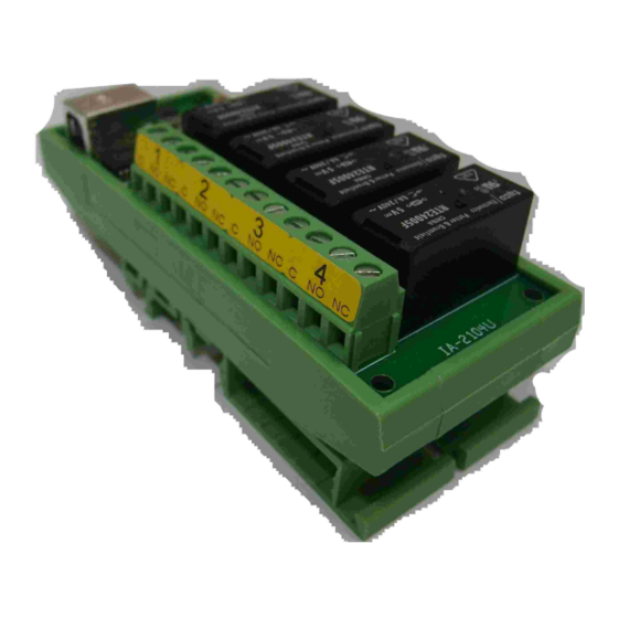
IA-2104-U 4 Relays Controlled Module Pin Assignment - INPUT - USB JP1 - User Defined Jumper LED LD1 - User Defined LED & USB Connection LED LED LD2 - Option - Relays 1-4 Terminals - Normally Close - Normally Open... -
Page 7: Software Installation
2 of ‘Locating the new COM port’, earlier at this page). Select ‘19200’ to fit into the right of the ‘Baud’ label (in case that the IA-2104-U is at its default setting stage). Press the ‘Search’ button and wait for the utility to list all chained items. - Page 8 Controlled Module Software Installation Address Configuration Start IA-3000 Utility. Search then Select the desired IA-2104-U module. Choose ‘Config’ at the upper left screen location. Define the desired address right to the ‘Address’ label. Update the module using the ‘Update’ button.
-
Page 9: Command Set
IA-2104-U 4 Relays Controlled Module Command Set The following table is a quick reference table for the IA-2104U , A host computer / PLC may control the IA-2104 by simply sending ASCII commands though a standard COM port. Each command is structured from a delimiter character, modules address, command character, data if any carriage return character. -
Page 10: Get Device Name
IA-2104-U 4 Relays Controlled Module ?aa0(cr) Function Get Device Name Description Request the Device model name. Can be used to identify the connected module type at the specified address. Syntax ?aa0(cr) Delimiter character Hexadecimal address of the device Get device Model command... -
Page 11: Get Device Firmware
IA-2104-U 4 Relays Controlled Module ?aa1(cr) Function Get Device Firmware Version Description Request the Device version. Syntax ?aa1(cr) Delimiter character Hexadecimal address of the device Get device Version command (cr) Carriage Return - End of command Response _NNNN(cr) if the command was valid... -
Page 12: Get Relays Status
IA-2104-U 4 Relays Controlled Module ?aa2 (cr) Function Get Relays Status Read relays present status. Description Syntax ?aa2(cr) Delimiter character Hexadecimal address of the device Read relays status (cr) Carriage Return - End of command _DDDD(cr) If the command was valid... -
Page 13: Get Device Mode
IA-2104-U 4 Relays Controlled Module ?aa5(cr) Function Get Device Mode Description This command reads the module operation mode Syntax ?aa5(cr) Delimiter character Hexadecimal address of the device System Mode command (cr) Carriage Return - End of command Response _dd(cr) if the command was valid... -
Page 14: Get Device Serial Number
IA-2104-U 4 Relays Controlled Module ?aaID(cr) Function Get Device ID Description This command reads the Device ID Syntax ?aaID(cr) Delimiter character Hexadecimal address of the device Command for read ID (cr) Carriage Return - End of command Response _ID NNNNNNNN (cr) -
Page 15: Get User Defined Jumper Setting
IA-2104-U 4 Relays Controlled Module ?aaS (cr) Function Get User Defined Jumper Setting Description Read Jumper Setting Syntax ?aaS(cr) Delimiter character Hexadecimal address of the device Read Jumper Setting (cr) Carriage Return - End of command Response _DD(cr) If the command was valid... -
Page 16: Set Relays Status
IA-2104-U 4 Relays USB Controlled Module !aa2dd(cr) Function Set Relays Status Description This command define’s module’s output state. !aa2dd (cr) Syntax Delimiter character Hexadecimal address of the device System control command Relay output activation command data for each nibble in hex format. -
Page 17: Activate Relay N
IA-2104-U 4 Relays USB Controlled Module !aa3dd(cr) Function Activate Relay N Description This command activate a single relay. Syntax !aa3dd(cr) Delimiter character Hexadecimal address of the module Single relay activation command N Relay ID in hex format N Relay ID in hex format... -
Page 18: De Activate Relay N
IA-2104-U 4 Relays Controlled Module !aa4dd (cr) Function De Activate Relay N Description This command De activate a single relay. Syntax !aa4dd(cr) Delimiter character Hexadecimal address of the module De activate relay N command Relay ID hex format Relay ID hex format... -
Page 19: Set Device Mode
IA-2104-U 4 Relays Controlled Module !aa5dd(cr) Function Set Device Mode Description This command sets the power-up mode and enables/disables error messages Syntax !aa5dd(cr) Delimiter character Hexadecimal address of the device System Mode command 8 mode control bits (00-FF) Bit# Function Enable Error Messages Disable Feedback messages on “!AA2”... -
Page 20: Set Baud Rate
IA-2104-U 4 Relays Controlled Module !aa6bb(cr) Function Set Baud Rate Description For compatibility with existing devices the IA-2104 can be set to other standard baud rates Syntax !aa6BB(cr) Delimiter character Hexadecimal address of the device Change device baud rate command... -
Page 21: Set Module's Address
IA-2104-U 4 Relays Controlled Module !aa7aa(cr) Function Set module’s address Description Each device must have a unique network address. This command defines a module’s address. Factory default is 00Hex. Syntax !aa7aa(cr) Delimiter character Hexadecimal address of the device Get device Version command... -
Page 22: Set Initial State
IA-2104-U 4 Relays Controlled Module !aaEdd(cr) Function Set State Description This command defines relays state on power-up. Syntax !aaEdd(cr) Delimiter character Hexadecimal address of the device System control command Relay output activation command data for each nibble in hey format. -
Page 23: Set User Defined Led
IA-2104-U 4 Relays Controlled Module !aaSdd(cr) Function Set User Defined LED Description This command defines user LED activation. !aaSdd (cr) Syntax Delimiter character Hexadecimal address of the device Set User Defined LED LED Activation Command. (cr) Carriage Return - End of command Response |dd(cr) if the command was valid.
Need help?
Do you have a question about the IA-2104-U and is the answer not in the manual?
Questions and answers