
Related Manuals for Dillon Precision Products Super 1050


Summary of Contents for Dillon Precision Products Super 1050
-
Page 1: How The Super 1050 Works: Stations
Super 1050 Instruction Manual Version 1.1 illon recision Products, Inc. Manufacturers of The World's Finest Loading Equipment... -
Page 2: Table Of Contents
Crimp Die - Station 8 RL 1050 vs. Super 1050 Trouble Shooting Maintenance Lubrication Points 22 - 23 Caliber Conversion Charts 24 - 25 Parts List Schematics 27 - 31 #11011 Spot Manuals Super 1050 manual folder SUPER 1050 Manual v1.1 9/01 WJC... -
Page 3: Back-Up Expander Die & Swager - Station
Seat bullets as close to maximum cartridge length as possible. Under some conditions, seating bullets exces- The Dillon Super 1050 reloader has been designed as a sively deep can raise pressures to unsafe levels. Refer to a commercial machine. Our expectation is that its life reliable loading manual for overall length (OAL). -
Page 4: Contents
Contents • Super 1050 machine with caliber spe- • Collection bin support bracket • Powder bar return rod assembly cific shellplate and loading dies • Bullet bin bracket • Primer early warning system installed and adjusted. -
Page 5: Powder Die - Station
How the Super 1050 Works Stations 1 - 8 (counterclockwise) toolhead and dies cut away for clarity Station 1 - The casefeed plunger inserts the Station 7 - In this station, the bullet is seat- case into the shellplate. ed to its proper depth. -
Page 6: Super 1050 Assembly
Super 1050 Assembly Your new Super 1050 has been assembled at the factory. All of the adjustments necessary to reload have already been made, in fact we’ve even adjusted the dies to reload the caliber you have chosen. However, before you can reload you must do some minor assembly. -
Page 7: Bullet Seating Die - Station
Clip Fig. 6 - Shown is the proper position of the power cable, clamp, and bin bracket. Fig. 8 - The end of the casefeed tube marked The casefeed mounting post assem- “up” snaps into the clip at the base of the bly (#20641) is attached to the case- casefeeder motor housing. -
Page 8: Powder Measure Adjustment
Loading Components rate readings. Your Super 1050 is equipped with a Powder Measure Adjustments Fig. 12 - Shown is the proper location of cartridge activated powder measure the cartridge collection bin. Note: the bul-... -
Page 9: Primer Magazine
and one small (#20062). Rule of thumb: Use the large bar whenever possible. Index a sized and primed case under the measure and operate the machine’s handle. Turning the powder bar adjust- ment bolt clockwise increases the pow- der charge – counterclockwise turns decreases the powder charge. -
Page 10: Electric Casefeeder
350 rifle cases. Fig 24 Precision offers an optional accessory to you funnel the primers in. Hold the Your Super 1050 is now charged with be utilized with the automatic powder tube in place as shown in Fig. 22, pull components and ready to go, but before measure at this station –... - Page 11 will continue to run until the tube is ready it for seating. If you count one 5. Remove the locator button full, at which point a micro-switch will second down, and one second up, (#20637*), extract the round and check temporarily stop the case flow.
-
Page 12: Adjustments
Swager don’t get caught and don’t hurry. Just Swaging on the Super 1050 is a sim- try to be smooth in your operation. The ple process and is necessary on all car- speed will come naturally and you’ll be... -
Page 13: Primer System Change Over Instructions
Primer System Change Over Loosen the lever arm bracket screw Instructions (#14037) and slide the bracket assem- bly up four inches and lock it in The Super 1050 has been shipped to place. Fig. 34 you with either the large or small... -
Page 14: Toolhead Removal
replace, the primer slide (#20318 - large Toolhead Removal or #20317 - small). Fig. 39 Fig. 37 - The four lock ring screws need only be loosened about four turns to remove the shellplate lock nut. Fig. 40 - A special screwdriver for the bush- Fig. -
Page 15: Shellplate Removal
sure everything is properly located. Die Adjustments With the handle in the down position, Station 2 - To install the size/decap die tighten the toolhead bolt with the Warning: Never attempt to deprime above mentioned wrench. live primers, an explosion may result. Shellplate Removal Move the toolhead down, by lower- Loosen the ejector tab screw... - Page 16 Fig. 49 - You don’t need any more expansion than what you see in this photograph. Fig. 51 - This photo shows the powder bar at the end of its travel. A properly expanded case should white cube must contact the powder show a slight flare at the case mouth.
- Page 17 Station 5 - Adjustment of the Powder While holding the powder measure in place, snug the lock ring using a 1- Die/Powder Funnel Cont... 1/8” wrench. Drop a case into the casefeed funnel and cycle the handle twice. The case Station 7 - General Information on Correct amount should now be in the shellplate at...
- Page 18 schematic of the cartridge. For example, .38 Special lists a maximum OAL of 1.55" (Lyman Reloading Handbook). If you’re seating the bullet to the can- nelure/crimping groove, the OAL should be well within the maximum OAL listed, however, use a set of dial calipers to check it.
-
Page 19: Rl1050 Vs. Super 1050
Leave the handle in the down posi- • The Super 1050 index lever has been case and the shellplate. Now secure the tion. With a wrench, screw the back- shortened considerably and will not lock ring (#20006*). -
Page 20: Trouble Shooting
5.) Bent or broken shellplate (#12600*). d.) Dirt in shellplate pockets. be used on both the Super 1050 and e.) Handle being moved too rapidly RL 1050 machines. NOTE: If you are on the down stroke. -
Page 21: Maintenance
case has been flattened out. (length and/or the ogive). c.) Use the proper seating stem for 2.) High primers: the type of bullet being used. a.) Adjust the primer push rod d.) Variations in case types and/or (#12819). lots – sort brass. b.) On .223 cases the swage back-up e.) Refer to a loading manual for rod (#13332) is down too far, slightly... -
Page 22: Lubrication Points
Bolt (#13333) 12995 12486 alignment pin alignment casefeed cam 13296 Super 1050 mainshaft 10999 12849 • Shellplate center hole. It’s easiest to large lubricate the shellplate center hole 13307 when changing from one caliber to •... - Page 23 Lube Points for the Super 1050 Towards the back of the machine, from the right side of the machine BUT lube the indexing lever cam surface NO MORE THAN 3/4". Using a grease Crank Assembly (#20312) and index lever shoulder...
-
Page 24: Caliber Conversion Charts
RL 1050 - Caliber Conversion Chart 20477 – .38/.357 Conversion 20482 – 9mm Conversion 20626 – .30 Carbine 12704 #2 Shellplate 12938 #5 Shellplate Conversion 14062 #2 Locator Buttons (6) 14060 #3 Locator Buttons (6) 12655 #8 Shellplate 13137 .38/.357 cal. Expander – D 12833 9mm cal. - Page 25 Super 1050 - Caliber Conversion Chart The Super 1050 loads all of the calibers listed for the RL 1050 as well as the calibers listed below. #21049 – .308 Conversion #21053 – .270 Conversion 11005 Super 1050 Adapter - .308 Win 11004 Super 1050 Adapter - .30-06 Win...
-
Page 26: Parts List
Super 1050 Parts Listing Part # Description Part # Description Part # Description 10991 Bin Support Bracket 13449 Toolhead Washer 13939 Body Collar Clamp – Part 10992 Inside Frame Stop 13475 Journal Key 1050 13943 Powder Bar Adjustment Screw 10993... - Page 27 Super 1050 Upper Machine Assembly #20420 – Toolhead Assembly 13005 - 13015 13342 refer to the caliber 13342 13957 conversion chart 13449 13449 Crimp 20320 Seating 20420 Expander – refer to the Sizing caliber 12819 conversion chart 20773 14067 12486...
- Page 28 Super 1050 Lower Machine Assembly Lower Machine Assembly Item A – Swage Rod Assembly Part # Description 10994 Mainshaft Pivot Pin - .560” dia. 14517 10996 Index Roller 10999 Super 1050 Mainshaft 11000 Crankshaft 11001 Crankarm 11002 Link Arm 11008...
- Page 29 Primer System Assembly - #20488 Upper Lower 13840 13001 13957 ;; ;; 13363 20488 13363 17604 13130 - large 14037 13222 - small 13423 14990 12995 20317 - small 13844 20318 - large 13746 13296 13936 13607 13858 11003 20773 12849 - large 13307 - small 13058...
- Page 30 Super 1050 Casefeeder Assembly Stock # Description 12144 Bullet Bin Bracket 13205 Post Bolts 13238 Bin Bracket 13271 Post Stud 13377 Bin Bracket Mount Screw 13400 Casefeed Bowl 1050 13400 13473 Casefeed Motor – 4 RPM (Not Shown) 13484 1050 Cartridge Bin...
- Page 31 Super 1050 Casefeed Sub Assemblies Powder Measure Assembly - #22221 13644 13951 13921 13882 20780 Item A – Casefeed Adapter – refer to the caliber 13943 conversion chart Frame Assembly 20062 Stock # Description 13815 13333 Bolt (Locator Tab) 13498...
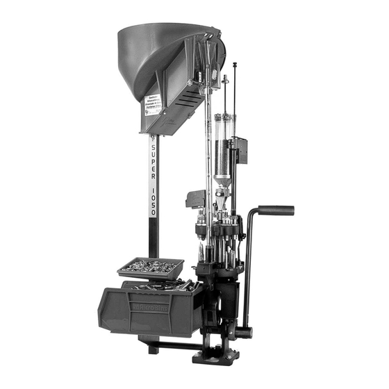
- Page 32 On the cover… The Super 1050 is pictured with optional accessories: Powder Check System #21044 Low Powder Sensor #16306 Bullet Tray #22215 Other accessories available for the Super 1050 include: Machine Cover #13239 Maintenance Kit & Spare Parts Kit #97018 The Blue Press, Dillon’s monthly catalog, has a complete...
Need help?
Do you have a question about the Super 1050 and is the answer not in the manual?
Questions and answers