
Summary of Contents for HORITA VS-50
-
Page 1: General Chapter
HORITA VS-50 VIDEO STOP WATCH USER MANUAL Doc. 070950 Rev. D (C) Copyright 2015 P.O. Box 3993, Mission Viejo, CA 92690 (949) 489-0240 www.horita.com... -
Page 2: Features Chapter
No part of this document may be copied or reproduced in any form or by any means without prior written consent of HORITA CO., INC., P.O. Box 3993, Mission Viejo, CA 92690. HORITA CO. INC. makes no warranties with respect to this documentation and disclaims any warranties of merchantability or fitness for a particular purpose. -
Page 3: Table Of Contents
Connecting the GPI Output Connecting the Internal GPI Pullout Resistor OPERATING THE VS-50 CHAPTER 4 VS-50 Mode Flow Diagram Explanation Figure 4.1, VS-50 Flow Mode Diagram LED Operation Entering and Exiting the Setup Menus Selecting Different Menu Items Changing the Selected Menu Item “DISPLAY SETUP”... - Page 4 The VS-50 also has provision for user entry of up to 9 lines of twenty characters each, for entering video source ID or other captioning and titling information. All of the VS-50 setup information, operating mode selection, and titling information is saved in a battery backed up, non-volatile memory, and restored at power up.
-
Page 5: Connecting The
However, do not use an adapter of more than 9 volts at 500 milliamperes or damage to the VS-50 may result. 3.2 Operating From Battery Power You can operate your VS-50 from battery power in order to use it in the field as a portable time and date or source ID inserter. -
Page 6: Operating The
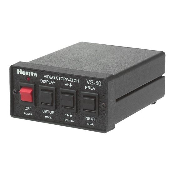
4. Reassemble your unit. OPERATING THE VS-50 To operate the VS-50 connect video in and out, the GPI output, apply power, and set the POWER switch to ON. A red LED above the power switch lights when the VS-50 is powered up. -
Page 7: Led Operation
Other selections, for example character size, produce their effect after the setup menu is exited. To display the setup menus, toggle the MODE switch to SETUP and release. Depending on the actual mode that the VS-50 is operating in, you may have to toggle the switch several times to enter a setup menu. The initial setup menu selected and displayed is the one that was used last. -
Page 8: Stopwatch Setup" Menu
ON = system reset RESET OFF = system reset complete System Reset initializes the VS-50 to a basic display of Stopwatch, Time, and Date 4.7 “STOPWATCH SETUP” Menu A typical STOPWATCH SETUP menu appears on the VS-50 screen as follows:... - Page 9 The following paragraphs provide a detailed explanation of each of the STOPWATCH SETUP menu items ITEM FUNCTION SELECTIONS COUNTER Unformatted counter HH:MM:SS display and counter HH = 00-99 Hours preset value MM = 00-59 Minutes SS = 00-59 Seconds DISPLAY Turns display ON = display ON ON and OFF...
-
Page 10: Time Setup" Menu
LAP remote inputs. LEV = selects level type control for RUN, REVERSE, OFF, and LAP remote inputs. 4.8 “TIME SETUP” Menu A typical TIME SETUP menu appears on the VS-50 screen as follows: *TIME SETUP* TIME HH:MM:SS DISPLAY START POSITION... -
Page 11: Date Setup" Menu
No separator except for a period whenever tenth of a second is displayed, and a space between Table 4.2, Time Display Formats 4.9 “DATE SETUP” Menu A typical DATE SETUP menu appears on the VS-50 screen as follows: *DATE SETUP* DATE MM-DD-YY DISPLAY... - Page 12 NOTE The Date value can be accessed for setting by using the POSITION switch to move the cursor up the screen into the DATE MM-DD-YY year fields. ITEM FUNCTION SELECTIONS DISPLAY Turns display ON = display ON ON and OFF OFF = display OFF START Starting character...
-
Page 13: Selecting Titling Mode And Entering And Editing Data
When the MODE switch is first actuated to DISPLAY after the VS-50 is displaying the normal stopwatch, time, date, and titles, the display is turned off. If actuated to SETUP, the VS-50 display is turned back on. In this manner the VS-50 display can be quickly switched on and off from the front panel switches. -
Page 14: Operating In Local Mode
Holding a preset input to ground for greater than 2 seconds causes the counter digit to quickly advance +/- automatically. Note that this preset value is retained in the VS-50 and is used to preset the Stopwatch counter whenever the PRESET/DOWN input is activated. -
Page 15: Gpi Output Signal Timing Versus Stopwatch Mode
On each second ON MIN On each minute Table 4.5, GPI Timing Versus Counter Mode 4.19 Remote Control Connector Remote control of the VS-50 is by way of two DB9 connectors labeled REMOTE-1 and REMOTE-2. REMOTE-1 Pin No. Name Type Function... -
Page 16: Cleaning
1. Check all coaxial cables for opens or shorts. 2. If using an AC power adapter different from the one supplied with the VS-50, make sure it supplies the VS-50 with at least 9 volts (maximum of 14 volts) when the VS-50 is switched on. -
Page 17: Horizontal Size Adjustment
LEVEL H SIZE Figure 5-1, Adjustment Locations 5.4 Horizontal Size Adjustment 1. Apply power to your unit and adjust H-SIZE control for the desired horizontal size. 5.5 Video Level Adjustment 1. Connect a 1-volt P-P video signal to VIDEO IN and a waveform monitor or oscilloscope to VIDEO OUT. Make sure the video output is terminated. - Page 18 3 Not Used 4 DWN/UP Set auto reload down counter 5 PRESET NEG Preset negative (minus) direction 6 PRESET SEC Preset seconds 7 PRESET MIN Preset minutes 8 PRESET HRS Preset hours 9 GND Signal ground POWER 3.5MM Mini Phone Switches And Controls POWER ON/OFF Toggle switch with red LED above...
Need help?
Do you have a question about the VS-50 and is the answer not in the manual?
Questions and answers