Table of Contents
Advertisement
Advertisement
Table of Contents
Troubleshooting

Subscribe to Our Youtube Channel
Related Manuals for Vaisala Indigo500 Series


Summary of Contents for Vaisala Indigo500 Series
- Page 1 M212287EN-N User Guide Indigo500 Series Transmitters Indigo510, Indigo520...
- Page 2 This product contains software developed disclosed to a third party without prior by Vaisala or third parties. Use of the written permission of the copyright holder. software is governed by license terms and Translated documents and translated...
-
Page 3: Table Of Contents
Table of contents About this document..................9 Version information..................9 Related manuals....................10 Documentation conventions................10 Trademarks......................11 Product overview...................12 Introduction to Indigo500 Series Transmitters..........12 2.1.1 Probe compatibility..................12 Indigo500 basic features and options............12 Indigo500 transmitter parts................14 2.3.1 Cable gland and conduit options............15 Touchscreen display.................. - Page 4 Indigo510, Indigo520 User Guide M212287EN-N Connecting probes..................44 3.4.1 Temperature compensation..............46 User interfaces....................47 Touchscreen display and main views............47 4.1.1 Graph data statistics................50 Web interface and main views...............51 Start-up......................53 Starting up transmitter using touchscreen display........53 5.1.1 Configuring network connection on touchscreen......54 5.1.2 Setting date and time on touchscreen..........
- Page 5 Table of contents Enabling Modbus TCP/IP in web interface..........92 Disabling temperature compensation in web interface......92 Exporting logged data...................93 Modbus......................94 Modbus overview................... 94 Unit identification of transmitter and probes..........94 Maintenance and troubleshooting............96 Cleaning......................96 Replacing probes................... 96 Updating transmitter software version............97 Restoring factory default settings...............
- Page 6 Indigo510, Indigo520 User Guide M212287EN-N List of figures Figure Indigo520 transmitter parts................. 14 Figure 2 Indigo510 transmitter parts, non-display version........15 Figure 3 Indigo520 cable gland and conduit options, example configurations....................16 Figure 4 Indigo510 cable gland options, example configurations...... 17 Figure 5 Indigo520 with optional BARO-1 barometer module, example configuration..................21 Figure 6...
- Page 7 List of figures Figure 38 Analog input configuration menu in web interface......88 Figure 39 Relays configuration menu in web interface...........89 Figure 40 Relays test mode in web interface..............91 Figure 41 Materials for recycling................... 112...
- Page 8 Indigo510 operating environment.............. 103 Table 16 Indigo510 inputs and outputs..............103 Table 17 Indigo510 compliance..................104 Table 18 Indigo500 Series mechanical specifications........... 105 Table 19 Indigo500 Series user interfaces..............105 Table 20 Indigo520 transmitter options..............105 Table 21 Indigo520 measurement performance............. 106 Table 22 Indigo520 operating environment.............
-
Page 9: About This Document
Chapter 1 – About this document 1. About this document 1.1 Version information This document provides detailed instructions for installing, using, and maintaining Vaisala Indigo510 and Indigo520 transmitters. Table 1 Document versions (English) Document Date Description code M212287EN-N November 2022 Added sections: •... -
Page 10: Related Manuals
Indigo500 basic features and options (page 12) • Starting up transmitter using touchscreen display (page 53) • Accessing configuration menu (page 73) 1.2 Related manuals For the latest versions of these documents, see docs.vaisala.com. Table 2 Related manuals Document code Name M212290EN Vaisala Indigo500 Series Transmitters Quick Guide 1.3 Documentation conventions... -
Page 11: Trademarks
Indicates that you need to take some notes during the task. 1.4 Trademarks Vaisalaâ and BAROCAPâ are registered trademarks of Vaisala Oyj. Modbusâ is a registered trademark of Schneider Automation Inc. Microsoftâ, Windowsâ, Internet Explorerâ, and Edgeâ are either registered trademarks or trademarks of Microsoft Corporation in the United States and/or other countries. -
Page 12: Product Overview
• GMP250 Series carbon dioxide probes • HPP270 Series vaporized hydrogen peroxide probes • MMP8 moisture in oil probe Indigo500 Series transmitters can also be connected to the MHT410 transmitter for display of measurement data and automation system connectivity. 2.2 Indigo500 basic features and options •... - Page 13 Chapter 2 – Product overview • Installation options: • Wall mounting • Wall mounting with adapter plate (retrofit to replace Vaisala 330 Series Transmitters such as HMT330) • DIN rail with adapter • Pole mounting Indigo510 features • 1 detachable probe •...
-
Page 14: Indigo500 Transmitter Parts
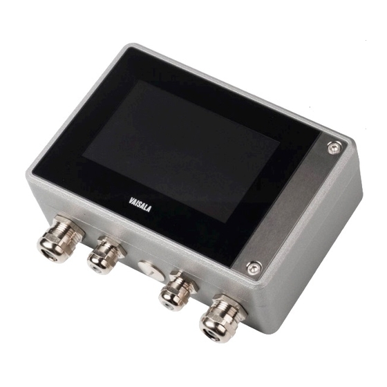
Indigo510, Indigo520 User Guide M212287EN-N 2.3 Indigo500 transmitter parts Figure 1 Indigo520 transmitter parts Touchscreen display (non-display model also available) Transmitter base Transmitter cover Cable gland for Ethernet cable and optional analog output cable (M20×1.5 lead-through) Cable gland for probe connection cable (M16×1.5 lead-throughs) Cable gland for optional relay cable and power cable in the PELV and AC (mains) power supply options (M20×1.5 lead-through) Hex screws for opening the cover... -
Page 15: Cable Gland And Conduit Options
2.3.1 Cable gland and conduit options The transmitter has 4 lead-throughs. The glands or conduit fittings for the lead-throughs are selected when ordering the transmitter. Unused lead-throughs are plugged. The following figure shows examples of different cable gland and conduit configurations available from Vaisala. -
Page 16: Figure 3 Indigo520 Cable Gland And Conduit Options, Example
Indigo510, Indigo520 User Guide M212287EN-N Figure 3 Indigo520 cable gland and conduit options, example configurations Cable gland, M20×1.5 Cable gland, M16×1.5 Cable gland with split bushing, M20×1.5 Conduit fitting, M20×1.5 for NPT1/2" conduit Pressure port, barometer module... -
Page 17: Touchscreen Display
Chapter 2 – Product overview Figure 4 Indigo510 cable gland options, example configurations Cable gland, M20×1.5 Cable gland, M16×1.5 Cable gland with split bushing, M20×1.5 More information ‣ Spare parts and accessories (page 110) 2.4 Touchscreen display The transmitter can be ordered either with a touchscreen display, or as a non-display model that uses an LED indicator for notifications. -
Page 18: Led Indicator (Non-Display Transmitter)
Indigo510, Indigo520 User Guide M212287EN-N 2.5 LED indicator (non-display transmitter) In the non-display transmitter model, the status of the transmitter and probe is indicated by LED color and whether the LED blinks. When the transmitter is ON, one of the LEDs is always illuminated (solid or blinking). -
Page 19: Output Options
Chapter 2 – Product overview 2.7 Output options The Indigo510 transmitter provides 2 analog output channels and an Ethernet connection for the Modbus TCP/IP protocol and web interface. The Indigo520 transmitter provides 4 analog output channels, 2 relays, and an Ethernet connection for the Modbus TCP/IP protocol and web interface. -
Page 20: Relays
Indigo510, Indigo520 User Guide M212287EN-N 2.7.3 Relays The Indigo520 transmitter provides 2 configurable relays that can be wired either as normally closed or as normally open. Use the touchscreen or web interface to configure the relay activation parameters. Relays are not available in transmitters that are powered with Power over Ethernet (PoE). -
Page 21: Baro-1 Barometer Module
2.9 BARO-1 barometer module The Indigo520 transmitter is available with a BARO-1 module. The BARO-1 barometer module uses a BAROCAPâ silicone capacitive absolute pressure sensor developed by Vaisala for barometric pressure measurement applications. The sensor has excellent hysteresis and repeatability characteristics, low temperature dependence, and very good long-term stability. -
Page 22: Data Logging
Indigo510, Indigo520 User Guide M212287EN-N More information ‣ Modbus reference (page 113) ‣ Modbus registers (page 114) 2.10 Data logging Data logging feature has changed. Installing software version 1.13 or later to replace software version 1.12 or earlier removes all previously logged data. Data logging is always on and collects data automatically into the non-volatile memory of the transmitter. -
Page 23: Ethernet Connection
Chapter 2 – Product overview Figure 6 Example of logged data The header shows the log's start time, time zone and selected log. The second header shows to which port the probe is connected, its vendor name, product code and serial number. This header is created every time a probe is disconnected or connected and after any power outages. -
Page 24: Safety
Indigo510, Indigo520 User Guide M212287EN-N You must use a shielded cable to meet the rated EMC performance of the device. More information ‣ Configuring network connection on touchscreen (page 54) ‣ Configuring network connection in web interface (page 66) 2.12 Safety This product has been type-tested for safety. - Page 25 Chapter 2 – Product overview WARNING! Connect only cables with temperature rating of minimum +80 °C (+176 °F) to the PELV power supply terminal. CAUTION! INDIGO520 PoE version transmitters shall be supplied by a Power Sourcing Equipment (PSE) unit which fulfils the requirements of IEEE802.3at specifications.
-
Page 26: Esd Protection
Do not replace detachable mains supply cables by inadequately rated cables. CAUTION! Do not use the transmitter in a manner not specified by Vaisala. If the transmitter is used in an unspecified manner, the protection provided by the equipment may be impaired. -
Page 27: Canada Ices-003 Compliance Statement
Chapter 2 – Product overview • Connect the equipment into an outlet on a circuit different from that to which the receiver is connected. • Consult the dealer or an experienced radio/TV technician for help. CAUTION! Changes or modifications to this equipment not expressly approved by the party responsible for compliance could void the user's authority to operate the equipment. -
Page 28: Installation
Choose the location of the transmitter so that the power outlet is accessible. Besides the standard wall mounting, the transmitter has the following mounting options: • Wall mounting with adapter plate (retrofit to replace Vaisala 330 Series Transmitters such as HMT330) -
Page 29: Standard Wall Mounting
Chapter 3 – Installation • DIN rail mounting • Pole mounting 3.2.1 Standard wall mounting • Allen key (4 mm), provided • Screws (2 pcs), provided • Crosshead screwdriver • Washers (2 pcs), provided • Drill with Ø 8 mm drill bit •... -
Page 30: Wall Mounting With Adapter Plate
• Wall plugs (4 pcs) • Screws 14 mm (2 pcs), provided • Washers (2 pcs), provided Using an adapter plate, you can install an Indigo500 transmitter to replace a Vaisala 330 Series Transmitter in the exact same location. -
Page 31: Figure 9 Wall Mounting With Adapter Plate
Chapter 3 – Installation Figure 9 Wall mounting with adapter plate 183 [7.2] 169 [6.7] Ø 7 [0.28] [in] Figure 10 Adapter plate dimensions 1. Attach the adapter plate to the mounting holes using 4 screws and 4 wall plugs. 2. Open the 2 hex screws on the cover of the transmitter using a 4-mm Allen key. 3. -
Page 32: Din Rail Mounting
Indigo510, Indigo520 User Guide M212287EN-N 3.2.3 DIN rail mounting • Allen keys (4 mm and 5 mm), • Washers (2 pcs), provided provided • DIN rail clip fasteners (2 pcs), • Screws 14 mm (2 pcs), provided provided Figure 11 Attaching DIN rail clip fasteners 1. -
Page 33: Pole Mounting
Chapter 3 – Installation 3.2.4 Pole mounting • Allen keys (4 mm and 5 mm), • Installation kit for pole or provided pipeline (item code 215108): • Screws 14 mm (2 pcs), provided • Fixing brackets (2 pcs) for • Washers (2 pcs), provided 100 mm poles •... -
Page 34: Figure 13 Attaching Transmitter To Mounting Plate - Vertical Pole Mounting
Indigo510, Indigo520 User Guide M212287EN-N Figure 13 Attaching transmitter to mounting plate - vertical pole mounting 1. Place the fixing brackets around the pole and attach the mounting plate to the brackets using 4 mounting nuts. Make sure that the arrow in the mounting plate points upwards. 2. -
Page 35: Wiring
• Open-ended wrenches of sizes 17 mm, 19 mm, 22 mm and 24 mm • Flat head screwdriver • Cable glands as required by your application (available from Vaisala) • Cables as required by your application (probe connection cables and power cables are available from Vaisala) 3.3.1 Power supply terminals and lead-through −... -
Page 36: Power Supply Terminals And Lead-Through − Ac (Mains) Power Option
(PELV) or AC (mains) power. For the M20×1.5 cable gland ordered together with the transmitter from Vaisala, the cable diameter is 5.0 … 8.0 mm (0.20 … 0.31 in). Tightening torque for the cable gland is 8 Nm. -
Page 37: Table 6 Ac Power Supply Input Terminals
CAUTION! Do not use the transmitter in a manner not specified by Vaisala. If the transmitter is used in an unspecified manner, the protection provided by the equipment may be impaired. -
Page 38: Relay Output Terminals And Lead-Through
Indigo510, Indigo520 User Guide M212287EN-N 3.3.2.1 Preparing AC (mains) power cable CAUTION! Only factory installed AC (mains) cables have been safety type tested and assembly tested with the product. Modifying or replacing the factory installed AC (mains) cable will void UL/SGS listing. •... -
Page 39: Analog Output Terminals And Lead-Through
For the M20×1.5 cable gland ordered together with the transmitter from Vaisala, the cable diameter is 5.0 … 8.0 mm (0.20 … 0.31 in). Tightening torque for the cable gland is 8 Nm. -
Page 40: Analog Input Terminals And Lead-Through
Indigo510, Indigo520 User Guide M212287EN-N For the M20×1.5 cable gland ordered together with the transmitter from Vaisala, the cable diameter is 5.0 … 8.0 mm (0.20 … 0.31 in). Tightening torque for the cable gland is 8 Nm. For the M20×1.5 cable gland with split bushing, the cable diameter is 7 mm (0.28 in). -
Page 41: Table 9 Analog Input Terminals
1 connection terminal. For the M20×1.5 cable gland ordered together with the transmitter from Vaisala, the cable diameter is 5.0 … 8.0 mm (0.20 … 0.31 in). Tightening torque for the cable gland is 8 Nm. -
Page 42: Ethernet Connector And Lead-Through
3.3.5.2 Analog input wiring with external power supply For the M16×1.5 cable glands ordered together with the transmitter from Vaisala, the cable diameter is 2.0 … 6.0 mm (0.08 … 0.24 in). Tightening torque for the cable gland is 6 Nm. -
Page 43: Probe Connection Terminals And Lead-Throughs
Before connecting wires or cables, make sure that the transmitter is powered off. For the M16×1.5 cable glands ordered together with the transmitter from Vaisala, the cable diameter is 2.0 … 6.0 mm (0.08 … 0.24 in). Tightening torque for the cable gland is 6 Nm. -
Page 44: Verifying Tightness Of Cable Glands
If you want to configure the probe settings, such as purge interval, you must do that before connecting the probe to the transmitter. To configure the probe, you can use the free Vaisala Insight PC software. For more information, see your probe's user guide and visit www.vaisala.com/insight. -
Page 45: Figure 16 Connecting Probes To Indigo500
If you have configured the transmitter to use outputs, the transmitter also notifies you of the state of the outputs. Connect only Vaisala Indigo-compatible probes to the transmitter. Figure 16 Connecting probes to Indigo500 Probe connection cable, probe 1... -
Page 46: Temperature Compensation
The probe heating functionality in HMP7 can be activated either through configuration code (set at the factory), or it can be activated using the Insight software and service cable (Vaisala part number 242659 or USB-2). Output parameters that are dependent on temperature measurement (such as relative... -
Page 47: User Interfaces
Chapter 4 – User interfaces 4. User interfaces 4.1 Touchscreen display and main views The touchscreen display starts up when you power up the transmitter. On the touchscreen display, you can: • View live measurement data numerically and graphically • View output status •... -
Page 48: Figure 18 Graph View On Touchscreen
Indigo510, Indigo520 User Guide M212287EN-N Figure 18 Graph view on touchscreen Slots for 1 … 2 configurable measurement parameters. Graph scale: Time scale of the graph. Graph data statistics: View the maximum and minimum values observed during the time scale of the graph. -
Page 49: Figure 19 Configuration Menu On Touchscreen
Chapter 4 – User interfaces Figure 19 Configuration menu on touchscreen Home: Return to Home views. Home settings: Configure Home views. Notifications: View all the notifications that are currently active. Inputs and outputs: Configure analog input, analog outputs, relays, and Modbus TCP/IP. Transmitter: Configure transmitter settings. -
Page 50: Graph Data Statistics
Indigo510, Indigo520 User Guide M212287EN-N 4.1.1 Graph data statistics You can view Graph data statistics in Graph view on the touchsceen display. Figure 20 Graph data statistics view on touchscreen Scale: Time scale of the graph data statistics. Start time, End time: Start and end time for the measurements shown in statistics. Measured parameters and their maximum and minimum values observed during the time scale of the graph. -
Page 51: Web Interface And Main Views
Chapter 4 – User interfaces 4.2 Web interface and main views Figure 21 Web interface and main views Home > Measurements: View live measurement data numerically and graphically. Add and remove measurement parameters (1 … 6). Home > I/O status: View the status of outputs, relays, and inputs. Notifications: View all notifications. - Page 52 Indigo510, Indigo520 User Guide M212287EN-N More information ‣ Starting up transmitter using web interface (page 61) ‣ Configuring web interface home view (page 84)
-
Page 53: Start-Up
Chapter 5 – Start-up 5. Start-up 5.1 Starting up transmitter using touchscreen display 1. Remove the plastic protection cover on the touchscreen display. 2. Power up the transmitter. Powering up takes some minutes. After the power-up, the Measurements view opens, showing the 2 preferred measurement parameters from each connected probe. -
Page 54: Configuring Network Connection On Touchscreen
Indigo510, Indigo520 User Guide M212287EN-N 4. The default language of the user interface is English. If you want to use another language, select it in Transmitter > Language. Your transmitter is now ready for operation. You can next go through these additional settings: •... -
Page 55: Figure 22 Network Settings On Touchscreen
Chapter 5 – Start-up Figure 22 Network settings on touchscreen 1. Make sure that the Ethernet cable is connected to the transmitter. The Ethernet connector's LED lights up. 2. Select the configuration menu symbol at the upper right corner of the touchscreen. 3. -
Page 56: Setting Date And Time On Touchscreen
Indigo510, Indigo520 User Guide M212287EN-N 6. Scroll to the end of the screen and select Apply to save your changes. 5.1.2 Setting date and time on touchscreen Figure 23 Date and time settings on touchscreen The transmitter uses UTC (Coordinated Universal Time) internally. Time and time stamps in the touchscreen are shown according to the time zone set in Transmitter >... -
Page 57: Configuring Units On Touchscreen
Chapter 5 – Start-up 3. To set date and time automatically: a. In Set date and time, select Automatically. b. Select Time zone. c. In NTP server addresses, configure the Network Time Protocol (NTP) servers that the transmitter will attempt to synchronize with. NTP synchronization requires that the transmitter has a network connection and the IP address of the NTP server is reachable. -
Page 58: Configuring Screen Lock On Touchscreen
Indigo510, Indigo520 User Guide M212287EN-N Figure 24 Units settings on touchscreen 1. Select the configuration menu symbol at the upper right corner of the touchscreen. 2. Select Transmitter > Units. 3. Select the unit type: default metric, default non-metric, or custom units. If you select default metric or default non-metrics units, all measurement parameters will use the selected unit type. -
Page 59: Figure 25 Screen Lock Configuration Menu On Touchscreen
Chapter 5 – Start-up Figure 25 Screen lock configuration menu on touchscreen 1. Select the configuration menu symbol at the upper right corner of the touchscreen. 2. Select Transmitter > Screen lock. 3. In Screen lock off/on, set screen lock on. Change PIN code view opens. - Page 60 Indigo510, Indigo520 User Guide M212287EN-N 5. In Auto screen lock, select the time period after which the configuration menu will be automatically locked. You can lock the screen manually by selecting Lock screen in the configuration menu. 6. If you want to change the PIN code, select Change PIN code. Type in the new PIN code and select Ok.
-
Page 61: Starting Up Transmitter Using Web Interface
Chapter 5 – Start-up 5.2 Starting up transmitter using web interface The transmitter has a web interface for remote access. Take the following steps to start using the transmitter through the web interface. Start up the non-display transmitter model using instructions in Connecting to web interface with a direct connection between transmitter and computer (page... -
Page 62: Connecting To Web Interface With A Direct Connection Between Transmitter And Computer
Indigo510, Indigo520 User Guide M212287EN-N 5. Open a web browser. In the address field, type https://<transmitter's IP address>:8443. • Example: https://172.24.65.229:8443 You can see the IP address of the transmitter on the touchscreen, at the bottom left corner of the configuration menu Your web browser may give a certificate error, but you can safely proceed to the transmitter's IP address. -
Page 63: Creating Web Interface Users
Chapter 5 – Start-up 5. Press the PRESS TO ACTIVATE WEB INTERFACE button with a pointed object to enable the use of configuration mode IP. The LED next to the button lights up. The transmitter's IP address: 192.168.5.20 SERVICE PORT PRESS TO ACTIVATE WEB INTERFACE RS-485... -
Page 64: Figure 27 User Creation Page
Indigo510, Indigo520 User Guide M212287EN-N Figure 27 User creation page The web interface has 2 user levels: • Administrator: Configuration rights. Can configure outputs and change transmitter settings. • Guest: View-only access. Can add and remove measurement parameters in the Measurements view. 1. -
Page 65: Logging In To Web Interface
Chapter 5 – Start-up 3. Create a username and password for the Administrator user, and select Next. 4. Create a username and password for the Guest user (optional), and select Finish. The web interface restarts. After the restart, you can log in using the credentials you just created. -
Page 66: Changing Language In Web Interface
Indigo510, Indigo520 User Guide M212287EN-N 2. Type a password. 3. Select Log in. The web interface opens in the Measurements view. 5.2.5 Changing language in web interface 1. Log in to the web interface. 2. The default language of the web interface is English. If you want to use another language, select it in User >... -
Page 67: Figure 28 Network Settings In Web Interface
Chapter 5 – Start-up Figure 28 Network settings in web interface 1. Log in to the web interface as an administrator user. 2. Select Transmitter > Network. 3. Select the setting type: • Select DHCP if the transmitter is in a network that assigns network settings automatically. -
Page 68: Setting Date And Time In Web Interface
Indigo510, Indigo520 User Guide M212287EN-N 4. If you selected Static IP, fill in the rest of the fields with information provided by your local network administrator: IP address The four part network ID of the transmitter. Subnet mask Used together with the IP address to determine which network the transmitter is a part of. -
Page 69: Figure 29 Date And Time Settings In Web Interface
Chapter 5 – Start-up Figure 29 Date and time settings in web interface The transmitter uses UTC (Coordinated Universal Time) internally. Time and time stamps in the web interface are shown according to the time zone set in Transmitter > Date and time. 1. -
Page 70: Configuring Units In Web Interface
Indigo510, Indigo520 User Guide M212287EN-N 4. To set date and time manually: a. In Set date and time, select Manually. b. Select Time zone, Date, and Time. 5. Select Apply. More information ‣ Data logging (page 22) ‣ Configuring web interface home view (page 84) ‣... -
Page 71: Resetting Pin Code In Web Interface
Chapter 5 – Start-up • A pointed object for pressing the button inside the transmitter. 1. When you are ready with the start up and have done the necessary configurations, press the PRESS TO ACTIVATE WEB INTERFACE button again to disable the use of configuration mode IP. -
Page 72: Figure 30 Screen Lock View In Web Interface
Indigo510, Indigo520 User Guide M212287EN-N Figure 30 Screen lock view in web interface 1. Connect to the web interface. 2. Log in to the web interface as an administrator user. 3. In Transmitter > Screen lock, select Reset PIN code. A confirmation window opens. 4. -
Page 73: Configuring Transmitter Using Touchscreen Display
Chapter 6 – Configuring transmitter using touchscreen display 6. Configuring transmitter using touchscreen display 6.1 Accessing configuration menu 1. If the transmitter's configuration menu is locked, unlock it by selecting the lock icon Type in the PIN code and select Ok. 2. Select the configuration menu symbol at the upper right corner of the screen. The configuration menu opens. -
Page 74: Figure 31 Configurable Home Views On Touchscreen
Indigo510, Indigo520 User Guide M212287EN-N • Measurements view • Graph view Figure 31 Configurable Home views on touchscreen Measurements view with slots for 1 … 4 measurement parameters Graph view with graphs for 1 … 2 measurement parameters You can navigate between the views by using the left and right arrows at the bottom of the touchscreen. -
Page 75: Configuring Analog Outputs On Touchscreen
Chapter 6 – Configuring transmitter using touchscreen display 3. In the Measurements tab, in Slot 1 ... 4, select which parameters are shown in the different slots in the Measurements view. 4. In the Graph tab, define what is shown in the Graph view: a. -
Page 76: Figure 32 Analog Outputs Configuration Menu On Touchscreen, General Tab Active
Indigo510, Indigo520 User Guide M212287EN-N Figure 32 Analog outputs configuration menu on touchscreen, General tab active The General tab contains the settings that are common for all analog output channels. The Output 1 … 4 tabs contain individual settings for each analog output channel. A circle next to the channel name indicates that the channel is on. - Page 77 Chapter 6 – Configuring transmitter using touchscreen display 5. Configure the analog output channel settings: a. In Parameter, select the probe and the measurement parameter that controls the output channel. The unit of the parameter is set automatically. b. In Scale low end and Scale high end, define the lower and upper ends of the measurement scale for the chosen output parameter.
-
Page 78: Analog Output Configuration Example
Indigo510, Indigo520 User Guide M212287EN-N 6.3.1 Analog output configuration example This example shows how to configure analog output channel 1 to use the following settings when a relative humidity probe is connected to the transmitter as Probe 1: • 4 … 20 mA current output •... -
Page 79: Configuring Analog Input On Touchscreen
Chapter 6 – Configuring transmitter using touchscreen display More information ‣ Configuring analog outputs on touchscreen (page 75) 6.4 Configuring analog input on touchscreen Analog input is not available in Indigo510 transmitters or transmitters that are powered with Power over Ethernet (PoE). Only 1 measurement probe can be connected to the transmitter when you power the analog input device through Indigo520 probe 2 connection terminal. -
Page 80: Configuring Relays On Touchscreen
Indigo510, Indigo520 User Guide M212287EN-N 3. In Analog input off/on, set analog input on. 4. To power your analog input device through Indigo520, in Analog input powering, set analog input powering on. To see the changes you made, select . Then use the left and right arrows at the bottom of the touchscreen to navigate to the I/O status view. -
Page 81: Relay Configuration Example
Chapter 6 – Configuring transmitter using touchscreen display 2. Select Inputs and outputs > Relays. 3. Select the relay you want to configure: Relay 1 or Relay 2. 4. Configure the relay settings: a. In Relay off/on, set the relay off to edit settings. b. -
Page 82: Relay Hysteresis
Indigo510, Indigo520 User Guide M212287EN-N Table 11 Relay wiring: Normally open (NO) Relay activation mode Measurement above/below Relay opened/closed limit Relay active above limit Above = Relay active Closed Below = Relay inactive Open Relay active below limit Above = Relay inactive Open Below = Relay active Closed... -
Page 83: Enabling Modbus Tcp/Ip On Touchscreen
Chapter 6 – Configuring transmitter using touchscreen display 6.6 Enabling Modbus TCP/IP on touchscreen 1. Select Menu > Transmitter > Network. 2. Make sure that Network off/on is set on, and that the network settings are set correctly. 3. Select Menu > Inputs and outputs > Modbus TCP/IP. 4. -
Page 84: Configuring Transmitter Using Web Interface
Indigo510, Indigo520 User Guide M212287EN-N 7. Configuring transmitter using web interface 7.1 Configuring web interface home view You can select how many measurement parameters (1 … 6) you want to see in the Measurements view of the web interface. Both Guest and Administrator users can configure the Measurements view. 1. -
Page 85: Configuring Analog Outputs In Web Interface
Chapter 7 – Configuring transmitter using web interface 7.2 Configuring analog outputs in web interface You need Administrator user rights for this task. Figure 36 Analog outputs configuration menu in web interface 1. Connect to the web interface. 2. Log in to the web interface as an administrator user. 3. -
Page 86: Testing Analog Outputs In Web Interface
Indigo510, Indigo520 User Guide M212287EN-N 6. Configure the analog output channel settings: a. In Output off/on, set the output channel off to edit settings. b. In Source, select the source for the measurement parameter that controls the output channel. c. In Parameter, select the measurement parameter that controls the output channel. d. -
Page 87: Figure 37 Analog Outputs Test Mode In Web Interface
Chapter 7 – Configuring transmitter using web interface Figure 37 Analog outputs test mode in web interface 1. Connect to the web interface. 2. Log in to the web interface as an administrator user. 3. Select Inputs and outputs > Analog outputs. 4. -
Page 88: Configuring Analog Input In Web Interface
Indigo510, Indigo520 User Guide M212287EN-N More information ‣ Configuring analog outputs in web interface (page 85) 7.3 Configuring analog input in web interface You need Administrator user rights for this task. Analog input is not available in Indigo510 transmitters or transmitters that are powered with Power over Ethernet (PoE). -
Page 89: Configuring Relays In Web Interface
Chapter 7 – Configuring transmitter using web interface 1. Connect to the web interface. 2. Log in to the web interface as an administrator user. 3. Select Inputs and outputs > Analog input. 4. In Analog input off/on, set analog input on. 5. - Page 90 Indigo510, Indigo520 User Guide M212287EN-N 2. Log in to the web interface as an administrator user. 3. Select Inputs and outputs > Relays. 4. Select the relay you want to configure: Relay 1 or Relay 2. 5. Configure the relay settings: a.
-
Page 91: Testing Relays In Web Interface
Chapter 7 – Configuring transmitter using web interface 7.4.1 Testing relays in web interface Figure 40 Relays test mode in web interface 1. Connect to the web interface. 2. Log in to the web interface as an administrator user. 3. Select Inputs and outputs > Relays. 4. -
Page 92: Enabling Modbus Tcp/Ip In Web Interface
Indigo510, Indigo520 User Guide M212287EN-N 7.5 Enabling Modbus TCP/IP in web interface You need Administrator user rights for this task. 1. Connect to the web interface. 2. Log in to the web interface as an administrator user. 3. Select Transmitter > Network. 4. -
Page 93: Exporting Logged Data
Chapter 7 – Configuring transmitter using web interface 7.7 Exporting logged data Exporting large amounts of logged data can result in huge data files and take a long time, up to several hours. Typical export time is 30 ... 90 min. Refreshing the page or logging out during the export will stop the export. -
Page 94: Modbus
Indigo510, Indigo520 User Guide M212287EN-N 8. Modbus 8.1 Modbus overview Indigo500 transmitters support the Modbus TCP/IP communication protocol (over Ethernet). The transmitter and the connected probes are treated as separate Modbus slaves, each with their own fixed unit identifier (unit ID) value. Note the following limitations of the Modbus implementation: •... - Page 95 Chapter 8 – Modbus For probe-specific register information, see the connected probe's Modbus documentation. More information ‣ Modbus reference (page 113)
-
Page 96: Maintenance And Troubleshooting
If you want to configure the probe settings, such as purge interval, you must do that before connecting the probe to the transmitter. To configure the probe, you can use the free Vaisala Insight PC software. For more information, see your probe's user guide and visit www.vaisala.com/insight. -
Page 97: Updating Transmitter Software Version
Before you start: • Make sure that you have the software update file locally on your computer. You can download the file from https://www.vaisala.com/en/lp/indigo500-software-download. • If your transmitter does not have a network connection, make sure that both the transmitter and the computer connected to it are set to use static network settings. - Page 98 Indigo510, Indigo520 User Guide M212287EN-N 3. In Transmitter > Software, select Browse, and browse to the software update file. 4. Select Update. Updating takes some minutes. The transmitter restarts. After the restart, you will be prompted to log in again. You can see the updated software version under Software System status.
-
Page 99: Restoring Factory Default Settings
Chapter 9 – Maintenance and troubleshooting 9.4 Restoring factory default settings You can restore all device settings to the factory default settings. This will take some minutes. CAUTION! A factory reset deletes all current settings of the device. After the factory reset, you need to reconfigure the settings, including outputs and relays. When you connect to the web interface the next time, you will be prompted to give the activation code and create new users. -
Page 100: Troubleshooting
If you have a problem with using the transmitter, check the following tables before contacting Vaisala. If the problem you have is not listed in the tables, or if the proposed solution does not fix the problem, contact Vaisala technical support. - Page 101 Chapter 9 – Maintenance and troubleshooting Problem: You cannot access the web interface login page. The Ethernet cable may be 1. Open the transmitter cover. disconnected from the 2. If the Ethernet connector's green light is not blinking, transmitter. reconnect the Ethernet cable. 3.
- Page 102 The probe sensor may be faulty, replace it. faulty. 4. If the indicator is blinking green, restart the transmitter. 5. If the problem still persists, contact Vaisala. Problem: Analog input is not available. Possible cause: Solution: You have not updated your Ensure you have updated to a software version that supports transmitter's software.
-
Page 103: Technical Data
Chapter 10 – Technical data 10. Technical data 10.1 Indigo510 specifications Table 14 Indigo510 transmitter options Property Description/Value Display • Capacitive touchscreen display • No display (indicator LED) Powering Protective extra-low voltage (11 … 35 V DC, 24 V AC ± 15% 50/60 Hz) Recommended when the transmitter is exposed to direct UV light, and for outdoor installations and high-humidity environments. -
Page 104: Table 17 Indigo510 Compliance
Indigo510, Indigo520 User Guide M212287EN-N Property Description/Value Protective extra-low voltage (PELV) 11 … 35 V DC, 24 V AC ±15 % 50/60 Hz, max. current 2 A Isolation voltage: 500 V AC, 1000 V DC PELV power cable temp. rating ≥... -
Page 105: Indigo520 Specifications
Chapter 10 – Technical data Property Description/Value FCC compliance FCC Part 15, Class B Table 18 Indigo500 Series mechanical specifications Property Description/Value NEMA rating NEMA 4: Hose down and splashing water, NEMA 250-2014 Type 4 Housing classification IK08, DIN EN ISO 11997-1: Cycle B (VDA 621-415) -
Page 106: Table 21 Indigo520 Measurement Performance
Indigo510, Indigo520 User Guide M212287EN-N Property Description/Value Powering • Protective extra-low voltage (15 … 35 V DC, 24 V AC ± 20%) • AC (mains) power (100 … 240 V AC 50/60 Hz) • Power over Ethernet (no analog outputs or relays) Recommended when the transmitter is exposed to direct UV light, and for outdoor installations and high-humidity environments. -
Page 107: Table 23 Indigo520 Inputs And Outputs
Chapter 10 – Technical data Property Description/Value IP rating IP66: Dust-tight. Protected from powerful water jets from any direction. Operating temperature With display −20 … +55 °C (−4 … +131 °F) Without display −40 … +60 °C (−40 … +140 °F) Without display with barometer module −40 …... - Page 108 Indigo510, Indigo520 User Guide M212287EN-N Property Description/Value Input impedances 200 Ω Isolation Isolated from power supply Overload protection 40 mA max. (reverse polarity protected) Analog outputs Number of analog outputs Isolation Isolated from power supply Selectable voltage output types 0 … 1 V, 0 … 5 V, 0 … 10 V, scalable Selectable current output types 4 …...
-
Page 109: Table 24 Indigo520 Compliance
CE, China RoHS, FCC, RCM, UKCA Listing marks UL Listed (USA and Canada) FCC compliance FCC Part 15, Class B Table 25 Indigo500 Series mechanical specifications Property Description/Value NEMA rating NEMA 4: Hose down and splashing water, NEMA 250-2014 Type 4... -
Page 110: Compatible Probes And Devices
Table 28 Other compatible devices Device or series Models MHT410 Moisture, Hydrogen and Temperature MHT410 Transmitter 10.4 Spare parts and accessories Table 29 Indigo500 Series accessories Item Item code Adapter plate DRW252186SP Installation kit for pole or pipeline 215108 Installation kit with weather shield... -
Page 111: Recycling
10.5 Recycling Recycle all applicable material. Disposal of Vaisala products is to be done according to local laws and regulations. We encourage end-users to segregate the products from other waste at end-of- life and use best available recycling practices to minimize related environmental impacts. -
Page 112: Figure 41 Materials For Recycling
Indigo510, Indigo520 User Guide M212287EN-N Electrical and electronical waste Metal waste Figure 41 Materials for recycling Table 31 Materials for recycling Part Material Recycling Device parts Top enclosure Aluminium alloy Electrical and electronical waste Screws Stainless steel Metal waste Barometer module Various materials Electrical and electronical waste Ribbon cable Various materials... -
Page 113: Appendix A: Modbus Reference
Appendix A – Modbus reference Appendix A. Modbus reference A.1 Unit IDs Table 32 Unit IDs of transmitter and probes Device Unit ID Transmitter (including analog input and optional barometer module) Probe connected to probe 1 connection terminal Probe connected to probe 2 connection terminal 242 For probe-specific register information, see the connected probe's Modbus documentation. -
Page 114: Modbus Registers
ProductName "Indigo5X0 Transmitter" “K0710040” SerialNumber Vaisala-specific device identification object. A.4 Modbus registers Registers are numbered in decimal, starting from 1. Register addresses in actual Modbus messages (Modbus Protocol Data Unit (PDU)) are in hexadecimal and start from zero. Register number 1 corresponds to address 0 in the actual Modbus message. -
Page 115: Status Registers
Appendix A – Modbus reference Register Address Register description Data format Unit number 0036 Validated current level of 32-bit float analog input (mA) or NaN if 0037 analog input is out of valid range (3.8 … 20.5 mA) Table 36 Integer measurement data registers (read-only) Register Address Register description... -
Page 116: Table 38 Error Flags (Read-Only)
Indigo510, Indigo520 User Guide M212287EN-N Table 38 Error flags (read-only) Register Address Register Data format Value number description 0202 Barometer error 16-bit unsigned 0x0000 OK flags integer 0x0004 Pressure out of range 0x0008 Pressure measurement error 0x0010 Manufactory error 0x0020 Module type not defined 0x0100 F meas 0x0400 Temperature meas... -
Page 117: Modbus Communication Examples
Appendix A – Modbus reference A.5 Modbus communication examples Reading RH value from HMP4 probe connected to the transmitter as Probe 1 The values returned by the device differ depending on the ambient conditions. Your device might not return exactly the same values. Request Response Bytes in the frame... - Page 118 Indigo510, Indigo520 User Guide M212287EN-N Communication description Register number 1 (1-based Modbus register number) = 0000 (0-based register address used in actual communication) based on the Modbus reference in HMP Series with MMP8 and TMP1 User Guide (M212022EN) Data format Two 16-bit Modbus registers interpreted as IEEE 754 binary32 floating point value, least significant word first Returned value...
-
Page 119: Index
Index Index accessories..............110 installation analog input............20 connecting probes..........44 analog outputs............19 mounting..............28 testing.............. 78, 86 wiring..............35 barometer module..........21 LED................18 cable glands............15, 44 maintenance..............calibration..............Modbus............83, 92, 94 cleaning..............96 communication examples......... 117 closing............... 28 device idenfitication........... 113 configuration............ - Page 120 Indigo510, Indigo520 User Guide M212287EN-N safety..............24, 26 screen lock PIN code..............71 software update............. 97 spare parts.............. 110 specifications Indigo510..............103 Indigo520.............105 startup..............53, 61 temperature compensation......83, 92 terminals analog input...........40–42 analog output............39 power supply..........35, 36 probe connection..........43 relay output............38 touchscreen............
-
Page 121: Maintenance And Calibration Services
Maintenance and calibration services Vaisala offers comprehensive customer care throughout the life cycle of our measurement instruments and systems. Our factory services are provided worldwide with fast deliveries. For more information, see www.vaisala.com/ calibration. • Vaisala Online Store at store.vaisala.com is available for most countries. - Page 124 www. v aisala.com...
Need help?
Do you have a question about the Indigo500 Series and is the answer not in the manual?
Questions and answers