Table of Contents
Advertisement
Quick Links
TASC-6100
LIQUID/GRANULAR
APPLICATION CONTROL SYSTEM
USER GUIDE
PN - 98-05018
R2
Software Version 1.30
CE & S
TANDARD
MID-TECH
MPH
MIDWEST TECHNOLOGIES, INC.
TASC-6100
Alt.-Rate
Rate Controller
Standard Rate
OFF
Midwest Technologies, Inc. of Illinois
Springfield, IL 62703
V
ERSION
®
ON
OPERATE
INC.
OFF
SET- UP
DEC.
%Rate
Product Vol.
Appl. Rate
Fan RPM
Total Applied
Area
Width
Speed
Distance
Scan
PSI/Prime
Test
Speed
DISPLAY SELECTOR
1 2 3
4 5 6 7 8 9
BOOMS
Advertisement
Table of Contents

Summary of Contents for Mid-tech TASC-6100
- Page 1 TASC-6100 LIQUID/GRANULAR APPLICATION CONTROL SYSTEM USER GUIDE PN - 98-05018 Software Version 1.30 CE & S TANDARD ERSION ® OPERATE INC. MID-TECH SET- UP MIDWEST TECHNOLOGIES, INC. DEC. %Rate Product Vol. Appl. Rate Fan RPM Total Applied Area Width Speed...
- Page 2 98-05018 TASC 6100 HANGE DATE: DATE CODE: PAGES AFFECTED: SW VERSION 4/24/98 98114 New Manual(TASC-6100 w/Fan RPM) 1.20 10/1/98 98114 A-4 (No Revision Change) 1.20 5/15/00 00060 All - New Format/SW, CE Console 1.30 2/20/00 01110 Corrected graphic, updatedlogo &...
-
Page 3: Table Of Contents
98-05018 TASC 6100 ABLE OF ONTENTS HANGE ABLE OF ONTENTS IST OF LLUSTRATIONS OW TO ANUAL HAPTER WITCHES AND ONTROLS ONSOLE WITCHES AND NDICATORS OWER WITCH ELECTOR WITCH INC / DEC S WITCH “ON/OFF” I ECTION NDICATORS WITCH ISPLAY ELECTOR WITCH MPLEMENT TATUS... - Page 4 98-05018 TASC 6100 HAPTER AINTENANCE LUSHING AND LEANING ONTROL ONSOLE ROUND PEED SENSOR RESSURE ENSOR ONVEYOR ENSOR ONTROL ALVE IRING ARNESS HAPTER ROUBLE HOOTING RROR ESSAGES IQUID RROR ESSAGES RANULAR RROR ESSAGES HAPTER MERGENCY PERATION ROUND PEED ENSOR AILURE LOW CONTROL ALVE AILURE LOWMETER OR...
-
Page 5: List Of Illustrations
98-05018 TASC 6100 List of Illustrations . 1-1. TASC C ONSOLE WITCHES AND NDICATORS . 1-2. D ISPLAY ELECTOR UNCTIONS PERATE . 1-3. D ISPLAY ELECTOR UNCTIONS . 1-4. TASC 6100 D EFAULT ALUES IQUID TANDARD . 1-5. TASC 6100 D EFAULT ALUES IQUID... -
Page 6: How To Use This Manual
ANUAL his manual is designed to provide you with the basic ® information needed to set up and operate the Mid-Tech TASC 6100 control system. Actual procedures may vary somewhat, depending on the configuration of your system. When you see "Mitch", he is pointing out special information that you should be aware of, regarding safety, preventing console damage, an easier way to perform an operation, etc.. -
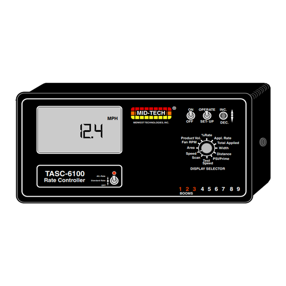
Page 7: Chapter 1 Switches And Console Switches And
Speed Distance memory so it "remembers" Scan PSI/Prime Test Speed DISPLAY SELECTOR the constants and data TASC-6100 Alt.-Rate Standard Rate Rate Controller previously entered, even 1 2 3 4 5 6 7 8 9 BOOMS with the power removed. Fig. 1-1. TASC NOTE: The “Auto Power Down Feature is only... -
Page 8: Inc / Dec S
98-05018 TASC 6100 INC / DEC S WITCH The Increase/Decrease (INC/DEC) switch (see #3 in Fig. 1-1) is used, in both the OPERATE and SET-UP modes, to adjust the values appearing in the display. “ON/OFF” I ECTION NDICATORS The boom section On/Off indicators (see #5 in Fig. 1- 1) indicate which boom sections the operator has selected. - Page 9 Speed Distance Scan PSI/Prime %Rate Test Application Rate: Speed Product Vol. Appl. Rate DISPLAY SELECTOR TASC-6100 Displays the Fan RPM Total Applied Rate Controller target application Area Width 1 2 3 1 2 3 5 6 7 8 9 5 6 7 8 9...
-
Page 10: Display Selector
Speed Distance %Rate Scan PSI/Prime Test Product Vol. Appl. Rate Speed DISPLAY SELECTOR TASC-6100 Fan RPM Total Applied Fan RPM: The current fan Rate Controller Area Width 1 2 3 5 6 7 8 9 RPM. calibration number. BOOMS... - Page 11 98-05018 TASC 6100 Display Selector - Operate Mode (Gran.) (See Fig. 1-2) Speed: The current vehicle speed. Area: Area Accumulator #1. The total area treated since the counter was last reset.* Fan RPM: The current speed of the fan (spinners). Product Vol.: Amount of product aboard the ve- hicle.** % Rate: The percent of programmed application rate...
-
Page 12: Implement Status Input
98-05018 TASC 6100 Display Selector - Set-Up Mode (Gran.) (See fig. 1-3) Speed: Ground Speed Override (GSO) value.** Area: Area Accumulator #2. The total area treated since the counter was last reset.* Fan RPM: The current fan RPM calibration number. This cal # can be set to zero to remove the fan RPM reading from the scan feature.** Product Volume: Used to set the full load capacity of the vehicle.**... -
Page 13: Ground Speed Override
98-05018 TASC 6100 "CLOSE" the control valve, depending on the response selected by the operator. (See Page 2-7). This feature allows the operator to control the operation of the control valve through the normal operation of the vehicle. The implement status input Fig. - Page 14 98-05018 TASC 6100 OPERATE MID-TECH TASC 6100, DISPLAYED VALUES WHEN IN MIDWEST TECHNOLOGIES, INC. SOFTWARE VER. 1.30 Specialists In Control System Electronics Since 1983 LIQUID STD MODE Preset #1 Use INC/DEC switch to change up or down % Rate Use INC/DEC switch to change up or down...
- Page 15 98-05018 TASC 6100 OPERATE MID-TECH TASC 6100, DISPLAYED VALUES WHEN IN MIDWEST TECHNOLOGIES, INC. SOFTWARE VER. 1.30 Specialists In Control System Electronics Since 1983 LIQUID PSI MODE Preset #1 Use INC/DEC switch to change up or down % Rate Use INC/DEC switch to change up or down...
- Page 16 98-05018 TASC 6100 OPERATE MID-TECH TASC 6100, DISPLAYED VALUES WHEN IN MIDWEST TECHNOLOGIES, INC. SOFTWARE VER. 1.30 Specialists In Control System Electronics Since 1983 GRANULAR MODE Preset #1 Use INC/DEC switch to change up or down % Rate Use INC switch to set full load,...
-
Page 17: Chapter 2 Calibration
The program being displayed, when the INC./ DEC. switch is released, is the program selected. If you have a question about which application to use, check with your dealer or call MID-TECH Customer Service. ELECTING NGLISH OR ETRIC... -
Page 18: Units For Each
98-05018 TASC 6100 NITS ISPLAY ELECTOR WITCH OSITION (Liquid Mode)** POSITION METRIC Speed Miles/Hour (mph) Kilometers/Hour (kmph) Field Area Acres (acre) Hectares (ha) Total Area Acres (acre) Hectares (ha) Product Vol. US Gallons (gal.) Liters (l) Appl. Rate US Gallons/acre (gpa) Liters/Hectare (l/ha) Total Applied US Gallons (gal.) Liters (l) -
Page 19: Liquid /Granularc
98-05018 TASC 6100 IQUID RANULAR OMMON ETUP TEMS ETTING PPLICATION ATES he TASC 6100 system is designed to maintain a constant, pre-selected application rate. In order for the control console to do this, the operator must OPERATE INC. enter the desired application rate. Two, switch selectable, SET- UP DEC. -
Page 20: Setting Boomw
% change value. BOOMS ETTING IDTHS he MID-TECH control console is designed to automatically compensate for changes in the swath width, caused by turning boom sections on or off. To accurately respond to changes in swath width, the console must know the length of each boom section. Use B, C, D, E the following procedure to set boom section widths. - Page 21 Use the following initial calibration numbers. It is important to field calibrate the distance sensor to insure maximum accuracy! ® MID-TECH COMPACT RADAR - 780 Dj RADAR - 1000 WHEEL SENSOR - 3500 SPEEDOMETER SENSOR - 3500...
- Page 22 98-05018 TASC 6100 A. Set the control console switches to the following settings: OPERATE INC. 1. Power SET- UP DEC. 2. Mode Selector SETUP % Rate Distance 3. Display Selector Product Vol. Application Rate Fan RPM Total Applied Area Impl. Width Speed Distance The display shows the current distance calibration...
-
Page 23: Setting The Hold
98-05018 TASC 6100 G. Stop the vehicle at the measured distance end marker. Compare the distance indicated by the console to the actual measured distance, to determine how much correction is necessary. For example: if the indicated distance is 396 Ft. after driving over a 400 foot range, the error in the distance calibration is 1.0%. - Page 24 98-05018 TASC 6100 turning on the Implement Status switch (closed circuit) the flow control valve is already open and product flow is instantaneous. This response assumes that some other device, such as a boom section valve, has stopped the product flow. When the operator selects the "Close"...
-
Page 25: Setting Theg
98-05018 TASC 6100 Use the following procedure to set the “All Booms OFF” response. OPERATE INC. A. Set the console to the following positions; SET- UP DEC. % Rate 1. Power Product Vol. Application Rate Fan RPM Total Applied 2. Mode Selector OPERATE Area Impl. -
Page 26: Product Volume
98-05018 TASC 6100 than the pre-selected GSO Speed, the console will sound an alarm and the display will flash a “Too Slow” message to warn the operator of possible over applica- tion. RODUCT OLUME ALUE Setting the Full Load Value The Full Load Value of the vehicle can be preset into the OPERATE INC. -
Page 27: Operating Under
TASC 6100 console is operating under external rate commands, it must be connected to the computer running the field mapping program through a Mid-Tech Data Link. Minimum and maximum anticipated rates must be programmed into the Standard Rate and Alt.-Rate positions of the Rate switch respectively and the Rate switch must be placed in the Alt.-Rate position. - Page 28 98-05018 TASC 6100 IQUID ETTING ORRECTION ACTOR (Pressure based (Pump L Psi (br)) only) NOTE: The Correction Factor is locked at 1.00 when in STnrd and rEFLO modes f you are spraying water solutions, the correction factor should be set to 1.00. If you are spraying a solution with a specific gravity different than that of water, adjust the correction factor according to the following chart.
- Page 29 (Mid-Tech) 38.8 1.25 inch (Raven) 75.0* 2.00 inch (Mid-Tech) 23.8 3.00 inch (Raven) 16.4* MID-TECH RAPID CHECK FLOWMETERS ANGE ANGE 1.00 inch 0.75 - 5 gpm 3200 1.50 inch 2.5 - 25 gpm 612.4 1.00 inch 2.5 - 16 gpm 1.50 inch...
- Page 30 98-05018 TASC 6100 range of speeds and the rate needed. When the nozzle is selected, find the column of nozzle ratings in "Gallons per Acre" at 10 MPH. Then, on the left of the chart, find the horizontal line representing the ratings at 30 PSI. Where the column and row intersect you will find the "Gallons per Acre"...
- Page 31 98-05018 TASC 6100 2.0 BAR. This is the value to enter into the console as the pressure sensor cal. #. For example, in the following chart, for a 8002-SS nozzle, the row for 2.0 BAR and column for 10 KPH cross at 78.0 Liters per Hectare, the pressure sensor cal.
- Page 32 A. Set the console to the following positions; BOOM CONTROL SWITCHES 1. Power switch MASTER 2. Mode Selector OPERATE ® AUTO MID-TECH MIDWEST TECHNOLOGIES, INC. PSI/Prime 3. Display Selector switch 4. At least one Boom switch (to release any trapped pressure) 5. Master switch 6. GSO switch 7.
- Page 33 98-05018 TASC 6100 more than 100 PSI (6.8 br). Push INC. switch again and hold for about 3 seconds. Display reads "PSi (br) xxx". The xxx is a pressure reading. The INC./DEC. switch can now be used to adjust the pressure reading on the console to match the reading on the pressure gauge.
- Page 34 98-05018 TASC 6100 A method similar to the following is recommended. 1. If using Pump L Psi, enter the appropriate "Correc- tion Factor" for the material that you will be using for the test (Use factor of 1.00 for Pump L STnrd applications) (see page 2-11).
- Page 35 98-05018 TASC 6100 Pressure Sensor: New Cal. # = M EASURED MOUNT NDICATED MOUNT If the measured amount is more than the indicated amount, the new cal# should be larger. If the measured amount is less than the indicated amount, the new cal# should be smaller. Flow Meter: NDICATED MOUNT...
-
Page 36: Granular Only Set -U
98-05018 TASC 6100 The calibration number can also be calibrated based on field experience. L Psi (bAr) Mode - Material left over - Adj. Cal. # down slightly - Short of material - Adj. Cal. # up slightly L STnrd Mode - Material left over - Adj. -
Page 37: Rate Sensorc
98-05018 TASC 6100 tion of the fan (spinner) must be entered using the following procedure: OPERATE INC. A. Set the console to the following positions; SET- UP DEC. 1. Power % Rate Product Vol. Application Rate 2. Mode Selector SET- UP Fan RPM Total Applied Area... - Page 38 98-05018 TASC 6100 Entering The Rate Sensor Calibration Number Enter this calibration number into the console using the OPERATE INC. procedure that follows. SET- UP DEC. % Rate A. Set the console to the following positions: Product Vol. Application Rate Fan RPM Total Applied Area...
-
Page 39: The Conveyor
98-05018 TASC 6100 to get an accurate measurement but be careful to keep the conveyor running full. As an example: if the truck scale reads in 20 lb. (10 Kg.) increments, at least 1000 lbs. (500Kg.) must be discharged to be able to calibrate within 2%. -
Page 40: Setting Auto Power
98-05018 TASC 6100 If the weight displayed on the console is greater than the weight actually measured, the calibration number will increase. J. Turn the Mode Selector to SET-UP and use the INC./DEC. switch to change the Spreader Con- stant. (REMEMBER, IF SPLIT DRIVE IS ACTIVE, THE BOOMS MUST BE ON.) Turn the booms OFF and switch the Mode Selector back to OPERATE, the corrected Indicated Amount will... - Page 41 98-05018 TASC 6100 B. Select the desired time using the INC/DEC switch. C. Exit this set-up mode by moving the Display Selector to another position, the Mode Selector to OPERATE, or turning the console OFF and back ON. NOTE: The “Auto Power Down Feature is only available on the CE version of the console (CE designation label on back of console).
- Page 42 98-05018 TASC 6100 This page purposely left blank CE & S TANDARD ERSION 2-26...
-
Page 43: Normal Start - Up And Changing Active Boom
98-05018 TASC 6100 Chapter 3 Operation Normal Start-up and Operation t is important to verify that the control console is programmed correctly before beginning operations each day. Refer to Chapter 2 to review the proce- dures for entering this information. A. -
Page 44: Boom Section
When the Master MASTER switch (or all Boom switches) is turned OFF, the ¨ AUTO MID-TECH application stops. This allows the operator to select MIDWEST TECHNOLOGIES, INC. active boom sections “on the go”, while depending on Fig. 3-1. Boom Section Switches the control system to adjust the flow rate appropriately. -
Page 45: Priming The Mainp
Speed Distance Scan PSI/Prime Test Speed affected. DISPLAY SELECTOR TASC-6100 Alt.-Rate Standard Rate Rate Controller 1 2 3 4 5 6 7 8 9 BOOMS The new application rate is maintained until a further Fig. 3-2. Changing App. -
Page 46: Rapid Unload Using
98-05018 TASC 6100 A. Set the console switches to the following posi- tions: OPERATE INC. 1. Power SET- UP DEC. OPERATE 2. Mode Selector % Rate Product Vol. Application Rate 3. Display Selector PSI/Prime Total Area Total Applied Field Area Impl. - Page 47 98-05018 TASC 6100 D. When the vehicle hydraulics are engaged, the conveyor operates at maximum speed. This procedure is useful for rapid unloading of the vehicle. E. To return to normal operation, hold the INC./ DEC. switch down for three to five seconds or move the Display Selector switch away from the PSI/Prime position.
- Page 48 98-05018 TASC 6100 Examples: GSO Switch "GSO Speed" Ground Speed Speed controlled "OFF" 5 mph 6 mph 6 mph "OFF" 5 mph 4 mph 4 mph "ON" 5 mph 6 mph 6 mph "ON" 5 mph 4 mph 5 mph CAUTION: When traveling at a speed slower than the GSO speed setting, this feature will cause the product to be applied at a rate consistent with the...
- Page 49 Flushing and Cleaning lways follow carefully the chemical manufacturer's directions regarding cleaning and flushing. As a general rule, MID-TECH recommends the following. Do not leave chemicals in the applicator overnight. The system should be cleaned at the end of each day's operation.
- Page 50 TECHNOLOGIES are inherently rugged. However, continued use eventually wears the internal bearings and shafts until the flowmeter becomes inaccurate. Replacement kits are available to repair the flowme- ters. Contact your MID-TECH dealer for these parts. CE & S TANDARD ERSION...
- Page 51 Wiring Harness ost failures of electronic systems, like the MID-TECH control system, are the result of broken wires or poor connections. Taking time to periodically inspect and clean the wiring harness will help prevent these types of failures.
- Page 52 NOTICE: A Returned Material Authorization Number (RMA #) must be obtained from Mid-Tech or your dealer for all items returned to Mid-Tech for repair or replacement. Mid-Tech product(s) returned for repair or re- placement must be cleaned and free of all chemical contamination before arriving at the Mid-Tech facility.
- Page 53 TASC 6100 Chapter 5 Trouble Shooting - Error Messages Trouble shooting of the Mid-Tech control system begins when the control console senses a problem or inconsistency in the system. When this happens, the control console alerts the operator with a visual and audible alarm. The following charts present the error messages that may appear on the display and possible causes and remedies.
- Page 54 Strainer or nozzle screens plugged. Pump L (Cont.) Pressure LOW, main strainer; Pressure HIGH, nozzle screens. Contact your MID-TECH Not a diagnostic function in Err 2 dealer if you see this the TASC 6100 console. message on a TASC 6100 controller. Err 3 Console is not receiving pulses from the flow sensor.
- Page 55 Control” port on back of console, to flowmeter for bad connections, abrasions, and pinched or broken wires. Err 4 Contact your MID-TECH Not a diagnostic function in dealer if you see this message the TASC 6100. on a TASC 6100 controller.
- Page 56 98-05018 TASC 6100 Hold down the decrease Err E Memory error. switch until the alarm stops. Check for any constants that This is often the result of a may have been set to zero poor battery connection. and re-enter the correct values.
- Page 57 Worn hydraulic pump or Check hydraulic pump or motor. motor output and rebuild or replace as necessary. Not a diagnostic function Contact MID-TECH if Err 2 in the TASC 6100. you see this message on a TASC 6100 controller. CE & S...
- Page 58 Test rate sensor and replace if faulty. Not a diagnostic function Contact MID-TECH if Err 4 in the TASC 6100. you see this message on an TASC 6100 controller. Application rate is Check, at the valve...
- Page 59 98-05018 TASC 6100 Incorrect switch se- Consult Operator's quence is selected on the Manual for the correct console. switch sequence. Err E Memory error. Hold down the decrease switch until the alarm This is often the result of stops. Check to see a poor battery connec- which constants have tion.
- Page 60 98-05018 TASC 6100 This page purposely left blank CE & S TANDARD ERSION...
- Page 61 MASTER ¨ AUTO A. Disconnect the speed sensor cable from the back MID-TECH MIDWEST TECHNOLOGIES, INC. of the TASC 6100 console. B. With the vehicle stopped, condition the console OPERATE INC.
- Page 62 GSO speed, the application is nearly exact. F. The console still keeps track of the Total Applied, and the system still adjusts to changes in boom MID-TECH recom- width. These functions can be monitored on the mends this procedure as display.
- Page 63 CAUTION. MARK THE VALVE POSI- TION BEFORE REMOVING ACTUATOR. FULL OPEN TO FULL CLOSE IS ONLY 90 For machines that use Mid-Tech's ROTATION. Alt.-Rate EXR II hydraulic control valve to regulate the Standard Rate...
- Page 64 1. Turn ON the desired boom sections and Auto allow spray. BOOM CONTROL SWITCHES 2. Use a nozzle chart to determine the boom pressure that gives the desired application rate at the target speed. MASTER ¨ AUTO MID-TECH MIDWEST TECHNOLOGIES, INC. CE & S TANDARD ERSION...
- Page 65 INC./DEC. switch. Areas accumulate normally. Speed reads correctly. MID-TECH recommends this procedure as a temporary, emergency procedure only. The prob- lem should be resolved as soon as possible to allow full automatic control of the sprayer to be reestab- lished.
- Page 66 98-05018 TASC 6100 This page purposely left blank CE & S TANDARD ERSION...
- Page 67 98-05018 TASC 6100 A - S PPENDIX YSTEM IAGRAMS Appendix A System Diagrams CE & S TANDARD ERSION...
- Page 68 98-05018 TASC 6100 Fig. A1 - Typical Flow/Pressure Based Wiring Diagram CE & S TANDARD ERSION...
- Page 69 98-05018 TASC 6100 Fig. A 2. Typical Flow/Pressure Based Plumbing Diagram CE & S TANDARD ERSION...
- Page 70 98-05018 TASC 6100 Fig. A 3. Typical TASC 6100 Granular System Wiring Diagram CE & S TANDARD ERSION...
- Page 71 98-05018 TASC 6100 Fig. A 4. TASC 6100 w/Auto Tip Control Wiring Diagram CE & S TANDARD ERSION...
- Page 72 98-05018 TASC 6100 VALUES DISPLAYED BY TASC 6100 FILL OUT BEFORE CALLING FOR FASTER SERVICE SOFTWARE VERSION: ____________________ Number displayed when console first powers up; e.g. 1.20 MODE SWITCH SETTING OPERATE SET-UP AREA FAN RPM PRODUCT VOL. % RATE APPLICATION RATE TOTAL APPLIED IMPL.
- Page 73 98-05018 TASC 6100 Appendix B - System Overview Appendix B System Overview CE & S TANDARD ERSION...
- Page 74 Fan RPM Total Applied Area Width Speed Distance Scan PSI/Prime Test Speed DISPLAY SELECTOR TASC-6100 Rate Controller 1 2 3 4 5 6 7 8 9 BOOMS Rate Change Application Rate Commands Data Boom Width Data CE & S TANDARD...
- Page 75 Width Speed Distance Scan PSI/Prime Test Speed DISPLAY SELECTOR TASC-6100 Rate Controller 1 2 3 4 5 6 7 8 9 BOOMS Fig. B-2. TASC 6100 Console TASC 6100 System Components ach of the five major components are described below so the operator has a general under standing of how each part performs its job.
- Page 76 If the sensor meets the accuracy Speed Radar requirements of the TASC 6100 system, it can often be adapted for use with the TASC 6100 Console. ® Check with your MID-TECH dealer, or the factory, regarding the use of a specific sensor. 3. A PPLICATION...
- Page 77 TASC 6100 system, as long as the flowmeter measures the total liquid flow to the booms. ® Check with your MID-TECH dealer, or the factory, regarding the use of a specific flowmeter. Note: Some flowmeters may require a special adapter cable.
- Page 78 If the valve meets the speed and precision requirements of the TASC 6100 system, it can possibly be adapted for ® use. Check with your MID-TECH dealer, or the Fig. B-7. Flow factory, about the use of a specific valve.
- Page 79 MIDWEST TECHNOLOGIES, INC. Fig. B-10. Data Link XTERNAL RATE ONTROL Using the Mid-Tech Data Link, the TASC 6100 console is capable of operating under the control of external rate commands from a large variety of GPS/GIS and Field Control systems.
- Page 80 98-05018 TASC 6100 This page purposely left blank CE & S TANDARD ERSION...
- Page 81 98-05018 TASC 6100 Appendix C - Glossary/Tables Appendix C Glossary/Tables CE & S TANDARD ERSION...
- Page 82 Control Console, a rate sensor device, and a servo control. This system is designed to control product to a target rate. Flowmeter - A device which measures volumetric liquid flow. Mid-Tech uses two different basic types of flowmeters. CE & S TANDARD...
- Page 83 98-05018 TASC 6100 Standard Flowmeters - Each standard flowmeter has a standard range that it can accurately measure. To change ranges requires changing flowmeters. Rapid Check Flowmeters - Similar to a standard flowmeter but has several different “inserts”, each with a different effective range, that can be installed.
- Page 84 Nitrogen to be targeted and recorded. Returned Material Authorization Number (RMA) - A number obtained from Mid-Tech or your dealer, which serves as your approval to return the item and informs Mid-Tech of the circumstances of the return so that proper action (repair, replacement, credit, etc.) can be initiated quickly upon receit of...
- Page 85 98-05018 TASC 6100 SEFUL ORMULAS Noz. Press. = [(Rate x Speed x Noz.Spacing) / (GPM40 x 939.2)]2 Where; Rate = GPA , Speed = MPH, Noz. Spacing = Inches and GPM40 = Noz.Flow @ 40 PSI GSOP. Min = [GPM40 x 939.2 x (PMin)1/2] / (Noz. Spacing x GPA) GSO(10 PSI) = (GPM40 x 2970) / (Noz.
- Page 86 98-05018 TASC 6100 ALIBRATION UMBERS Booms: 1. _____ 3. _____ 5. _____ 7. _____ 9. _____ 2. _____ 4. _____ 6. _____ 8. _____ C. _____ : _______ ISTANCE : _______ ETER ISCELLANEOUS OTES CE & S TANDARD ERSION...
Need help?
Do you have a question about the TASC-6100 and is the answer not in the manual?
Questions and answers