
Subscribe to Our Youtube Channel
Summary of Contents for BOLAB Systems 100-TS
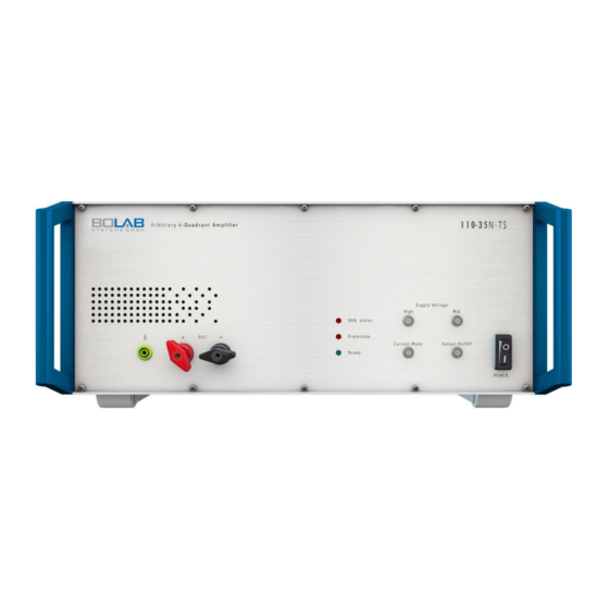
- Page 1 Operating Instructions 100-TS systems Arbitrary 4-quadrant voltage or current amplifier 500 W / 1,000 W Your contact:...
-
Page 3: Table Of Contents
Connections for 4 HE devices ................25 7.2.3 Component description - back ................ 26 Detailed description of components ..............31 7.3.1 Analogue outputs ....................31 7.3.2 Analogue inputs ....................33 7.3.3 Digital inputs/outputs ..................35 BOLAB 100-TS Table of contents Page 3... - Page 4 12.5 100-75N-TS / 500 W – 1,000 W ................62 13 Troubleshooting ........................64 14 Maintenance .......................... 65 14.1 Calibration ........................65 15 Cleaning and Care ........................ 66 16 Recycling/Disposal/Environmental Protection ..............67 BOLAB 100-TS Table of contents Page 4...
-
Page 5: About These Operating Instructions
1.2 Copyright protection These operating instructions may not be reproduced in any form, even in the form of extracts, without the written permission of BOLAB Systems GmbH, in accordance with DIN EN 16016. We reserve the right to make technical changes at any time, especially if these changes improve the performance of the product. -
Page 6: Limitation Of Liability
The information in these operating instructions should always be follow when handling the device. This applies to the operation, maintenance and repair of the 100-TS series. Failure to comply with such instructions or warnings in these operating instructions is a violation of the safety standards for the respective area of application. -
Page 7: Representation Conventions
One or more words in bold represent a term that is also found on the product. 1. Instructions with a fixed sequence are displayed in a numbered list. Results or outcomes of these actions are shown by “����”. BOLAB 100-TS Representation conventions Page 7... - Page 8 Other icons Icon Meaning Icon Meaning Direct current Alternating current AC and DC Operating voltage Protective earthing Operating voltage Ground terminal Reference terminal Positive terminal Negative terminal Ground BOLAB 100-TS Representation conventions Page 8...
-
Page 9: Safety
Avoid the device coming into contact with liquids or moisture. • Before installing, cleaning, maintaining, or repairing the device, turn it off completely. • Do not clean the device in running water or by immersing it in liquid. BOLAB 100-TS Safety Page 9... -
Page 10: Safety Instructions For Parallel Operation
Comply with all the safety regulations that are detailed in this documentation. Improper use invalidates any liability claims. 3.3.2 Software The BOLAB WaveMaster software is a computer program developed to remotely control and configure BOLAB power amplifiers. Observe the specified data and applications BOLAB 100-TS Safety Page 10... -
Page 11: Users
Qualified persons within the meaning of the safety information in this documentation are those who are authorised to commission and operate systems in accordance with the safety technology standards. BOLAB 100-TS Safety Page 11... -
Page 12: Transport And Storage
19” cabinet. CAUTION Use the supplied or appropriate packaging material for storage and transport. In order to lift the device, hold it by the housing with both hands. BOLAB 100-TS Transport and storage Page 12... -
Page 13: Scope Of Delivery
Check the package contents for completeness after unpacking. Keep the packaging for future transport, e.g. for annual calibration. Check the device for visible damage. Report any transport damage to the carrier and the supplier immediately. Number/component Description Amplifier Mains cable USB cable Operating Instructions BOLAB 100-TS Scope of delivery Page 13... -
Page 14: Basic Device Information
Do not continue if a protection is triggered on the system. The problem must be analysed and resolved first. Reasons for triggering protection may include: • Overvoltage • Overcurrent • Power-on peak current • Overvoltage protection • Excessive power dissipation • Overheating • Hardware defective BOLAB 100-TS Basic device information Page 14... -
Page 15: Voltage Ranges
Voltage ranges using the example of a BOLAB 105-70N-TS: Total voltage range: -16 V to +70 V Voltage range Low: -16 V to +16 V Voltage range Mid: -16 V to +27 V Voltage range High: -16 V to +70 V BOLAB 100-TS Basic device information Page 15... -
Page 16: Quadrants
The BOLAB amplifier systems work in all 4 quadrants. Depending on the load or the control voltage specification, the systems work in the respective quadrant. Sink Source Source Sink Figure 2: 4 quadrants BOLAB 100-TS Basic device information Page 16... -
Page 17: Basic Set-Up
CAUTION If you do not observe these and the following rules, no warranty claims may be asserted in the event of a device fault or destruction. BOLAB 100-TS Basic device information Page 17... - Page 18 Figure 3: Oscillation at the amplifier output CAUTION Only use individual active probes or differential probes for each individual channel if you are measuring at the main output of the system with e,g, an oscilloscope or data acquisition unit. BOLAB 100-TS Basic device information Page 18...
-
Page 19: Device/Component Description
Shutdown because the permissible overvoltage has been exceeded. o Shutdown because the overcurrent limit has been exceeded. o Shutdown because a maximum power-on peak current has been exceeded. o Shutdown because the voltage measured at the amplifier output has been exceeded. BOLAB 100-TS Device/component description Page 19... - Page 20 • LED flashes quickly (~3/s) red: Hardware is defective. Contact the Customer Service of BOLAB Systems GmbH. 7.1.1.2 DAQ status LED: Shows whether a waveform is currently running: •...
- Page 21 Ground (negative socket) is insulated against the protective earth if the optional multi-channel insulation amplifier is installed. ADVICE If the device type has identical outputs at the rear, these are always connected in parallel with the outputs on the front. BOLAB 100-TS Device/component description Page 21...
- Page 22 7.1.1.10 Grounding connection: Connection to the potential output of the device: • Internal connection to the protective earth BOLAB 100-TS Device/component description Page 22...
-
Page 23: Back Of The Device
9. Digital inputs and outputs, counter 3. U monitor and I monitor outputs inputs and outputs, interlock 4. BNC cable bridge 10. AO_1 output 5. Bridge switch 11. Grounding connection 6. AUX input 12. Mains socket BOLAB 100-TS Device/component description Page 23... - Page 24 ADVICE The arrangement of the connections may differ depending on the device model. BOLAB 100-TS Device/component description Page 24...
-
Page 25: Connections For 4 He Devices
5. U monitor and I monitor outputs 14. Service USB 6. DAQ OUT 15. Device fuse 7. Amplifier Signal IN 16. Analogue inputs 8. Positive and negative outputs 17. Mains socket 9. Slave output 18. Grounding connection BOLAB 100-TS Device/component description Page 25... -
Page 26: Component Description - Back
Not used 1.2 – 7 DIO Synchronisation switch counters 2.2 – 7 DIO Not used 1.2 – 8 DIO 2.2 – 8 DIO Not used 1.2 – 9 DIO +5 V 2.2 – 9 DIO BOLAB 100-TS Device/component description Page 26... - Page 27 7.2.3.2 AO_1 output (AO_1 OUT) BNC output for a second analogue signal for analogue control of a separate amplifier or a power supply: • Output of an analogue voltage signal (waveform signal) from the WaveMaster software BOLAB 100-TS Device/component description Page 27...
- Page 28 WARNING Do not connect the outputs to the earth terminal or the protective earth. This is only permitted in certain cases if a multi-channel isolation amplifier is installed internally. Check with the manufacturer. BOLAB 100-TS Device/component description Page 28...
- Page 29 7.2.3.10 Bridge switch (Bridge ON/OFF) Switch for connection to another device in series: • Must be set to “ON” for one of the two devices for a connection of two devices in series BOLAB 100-TS Device/component description Page 29...
- Page 30 For more detailed information on the digital inputs and outputs, see Chapter • Internal connection to the protective earth 7.2.3.17 Mains socket • Cold device plug for power supply to the device • Observe the information on the rating plate. BOLAB 100-TS Device/component description Page 30...
-
Page 31: Detailed Description Of Components
330 ns. This BNC output socket on the back of the amplifier system is connected to the amplifier input “Amp IN” or “Signal IN” via a small BNC cable. Figure 10: Connection via BNC cable BOLAB 100-TS Device/component description Page 31... - Page 32 The two signals can run simultaneously with microsecond accuracy. The ratio for the control voltage for the additional amplifier or laboratory power supply can also be freely selected via the WaveMaster software. Figure 12: Analogue outputs BOLAB 100-TS Device/component description Page 32...
-
Page 33: Analogue Inputs
These values are converted into the actual current values in the WaveMaster software using the device-specific current factor. The remaining analogue inputs are located on the rear 15-pin SUB-D socket: Figure 15: 15-pin SUB-D socket for analogue inputs BOLAB 100-TS Device/component description Page 33... - Page 34 If necessary, check with BOLAB Support whether this functionality is installed in the device, as this is not visible from the outside. The software pre-assignment of pin 09 or the analogue input AI 10 is reserved for the analogue trigger function: BOLAB 100-TS Device/component description Page 34...
-
Page 35: Digital Inputs/Outputs
The BOLAB 4-quadrant amplifier system contains 24 digital inputs and outputs. ADVICE May vary with special versions. These inputs/outputs are located on the back of the amplifier systems. Figure 18: Rear of 4-quadrant amplifier Figure19: Terminal blocks BOLAB 100-TS Device/component description Page 35... - Page 36 When a waveform is started, a digital output is set to “High” at block 2.2, pin 1 during the entire waveform sequence, as long as the waveform is running and the waveform sequence is finished. BOLAB 100-TS Device/component description Page 36...
- Page 37 7.3.3.2 Digital trigger functions An external TTL signal can be used to start a waveform sequence at a precise time via the digital hardware trigger. This function is activated by selecting the “external trigger” in the BOLAB 100-TS Device/component description Page 37...
- Page 38 This is then also used to trigger data recording at the same time using an oscilloscope, for example. This means that the start of the waveform and the recording on any measuring device are synchronised with each other. Figure 24: Block 2.1, Pin 9 BOLAB 100-TS Device/component description Page 38...
- Page 39 This defined output is located on block 1.2 at pin 1 and generates the signal for resetting the “OVP protection” of the BOLAB interlock controller for a high-voltage power supply after it has been triggered. BOLAB 100-TS Device/component description Page 39...
- Page 40 This function is explained in more detail in separate documentation and an eLearning module created for this purpose, and is only here for the sake of completeness, in order to show the configuration of the digital inputs/outputs. Figure 27: Block 1.2, Pin 1 BOLAB 100-TS Device/component description Page 40...
- Page 41 1.2 – 8 GND 2.1 – 5 GND 6.1 – 5 GND 2.1 – 6 GND 1.1 – 8 GND 2.1 – 7 GND 2.1 – 8 GND 2.1 – 9 External trigger In BOLAB 100-TS Device/component description Page 41...
-
Page 42: Counter Inputs/Outputs
Figure 30: Configuration plan of counter inputs and outputs Two counter outputs are used to control an electrical switch for various voltage tests, in which load circuits or switching circuits have to be interrupted. The WaveMaster software BOLAB 100-TS Device/component description Page 42... -
Page 43: Interlock
(break). When the interlock is triggered, the output is switched off and the protection LED on the front lights up red. Figure 31: Rear of 4-quadrant amplifier BOLAB 100-TS Device/component description Page 43... -
Page 44: Aux In
There are two ways to implement this: a) Additional generation of the signal for AUX IN via the WaveMaster software. The second analogue output called AO_1 OUT is connected to the AUX IN input via a BNC cable bridge. BOLAB 100-TS Device/component description Page 44... - Page 45 The first control signal is provided by the WaveMaster software at the DAQ OUT output. The addition of the two signals creates a new waveform, resulting from the default signal from the WaveMaster software and the externally provided signal from the signal generator. BOLAB 100-TS Device/component description Page 45...
-
Page 46: Bridge
For the series connection of two devices, the bridge switch must be switched over for one of the devices: CAUTION With three or more devices in series, each device requires the optionally integrated multi-channel isolation amplifier. BOLAB 100-TS Device/component description Page 46... -
Page 47: Sense (Optional)
-30 V … +70 V -3.0 V … 7.0 V 110-70R-TS 105-75N-TS / -75 V … +75 V -7,5 V … +7.5 V 110-75N-TS 105-100N-TS / -100 V … +100 V -10 V … +10 V 110-100N-TS BOLAB 100-TS Device/component description Page 47... - Page 48 Middle operating voltage for middle output voltages and middle load currents • Low operating voltage for low output voltage and high load currents Check the data sheet to see which operating voltage ranges apply to your device. Special models may have different ranges. BOLAB 100-TS Device/component description Page 48...
-
Page 49: Installation
After switching on, allow the amplifier a warm-up phase of 15 minutes to stabilise its operating points. Only place the device or the 19" rack on a flat surface. BOLAB 100-TS Installation Page 49... -
Page 50: Using The Device For The First Time
AC 3 x 230 V Special models may also require other supply voltages. Refer to the rating plate on the back of the device for the actual permissible values! BOLAB 100-TS Using the device for the first time Page 50... -
Page 51: Connecting A Device To The Power Supply
2. Connect the mains cable to the power supply. 3. Turn on the fuse to start the device. 9.3 Connecting an external signal source The 100-TS series has one signal input, which offers advantages for large signal paths. ADVICE Always use high-quality, low-capacitance shielded cables (<60 pF/m). -
Page 52: Connecting The Load
The cable cross-section must be selected according to the max. current. The output of some 100-TS series models has 4 mm safety connections at the power output on the front. On the back, there are two amplifier outputs in the form of screw terminals. -
Page 53: Commissioning Of Current Amplifier Operating Mode
5. Allow the amplifier to warm up for 15 minutes to stabilise the operating points. The amplifier is now ready for operation. 6. Perform the test with the load and the correctly selected RC compensation. BOLAB 100-TS Using the device for the first time Page 53... - Page 54 WARNING Multiple tripping of the protective circuits, especially the “overcurrent” fault, places a load on the power components and must be avoided. BOLAB 100-TS Using the device for the first time Page 54...
-
Page 55: Automated Test Systems And Environments
For this functionality, a detailed guide is available for download on the BOLAB Learning Management System (LMS). Alternatively, contact our Support for questions and assistance with programming. BOLAB 100-TS Automated test systems and environments Page 55... -
Page 56: Device Drawings
11 Device drawings 11.1 Front 4 HE 11.2 Transverse side 4 HE BOLAB 100-TS Device drawings Page 56... -
Page 57: Front 3 He
11.3 Front 3 HE 11.4 Transverse side 3 HE BOLAB 100-TS Device drawings Page 57... -
Page 58: Technical Data
Dimensions WxHxD (cm) 44.5 x 13.3 x 60.3 44.5 x 17.5 x 60.3 Delivery Instrument Weight 20 kg 40 kg 230 V Power supply (±10 %, 50 Hz ... 60 Hz) Protection 10 A BOLAB 100-TS Technical data Page 58... -
Page 59: 100-35R-Ts / 500 W - 1,000 W
Input impedance unbalanced 100 kΩ (1 kΩ) Instrument size 19”, 3 HE 19”, 4 HE Dimensions WxHxD (cm) 44.5 x 13.3 x 60.3 44.5 x 17.5 x 60.3 Delivery Instrument Weight 20 kg 40 kg BOLAB 100-TS Technical data Page 59... -
Page 60: 100-70N-Ts / 500 W - 1,000 W
CC mode (option) Depending on RC network Input impedance unbalanced 100 kΩ (1 kΩ) Instrument size 19”, 3 HE 19”, 4 HE Dimensions WxHxD (cm) 44.5 x 13.3 x 60.3 44.5 x 17.5 x 60.3 BOLAB 100-TS Technical data Page 60... -
Page 61: 100-70R-Ts / 500 W - 1,000 W
Sink power 240 W 470 W Slew rate 100 V / μs CV mode frequency bandwidth DC – 200 kHz Small signal DC – 1 MHz (-3 dB) CC mode (option) Depending on RC network BOLAB 100-TS Technical data Page 61... -
Page 62: 100-75N-Ts / 500 W - 1,000 W
1 V / 10 V (voltage) Monitor output 1 V / 10 A (current) Residual noise < 7 mV Source power 500 W 1,000 W Sink power 150 W 375 W Slew rate 100 V / μs BOLAB 100-TS Technical data Page 62... - Page 63 230 V Power supply (±10 %, 50 Hz ... 60 Hz) Protection 10 A Overvoltage protection (OVP) Overcurrent protection (OCP) Protective functions Overtemperature protection (OTP) Protection against excessive power dissipation Operating temperature 10°C - 55°C BOLAB 100-TS Technical data Page 63...
-
Page 64: Troubleshooting
13 Troubleshooting Technical Support If you have any technical questions, please contact Technical Support: BOLAB 100-TS Troubleshooting Page 64... -
Page 65: Maintenance
14 Maintenance 14.1 Calibration We recommend that you calibrate the device once a year. BOLAB 100-TS Maintenance Page 65... -
Page 66: Cleaning And Care
Improper cleaning can damage the device. This leads to defects on the device. • Use a soft and damp cleaning cloth to gently clean the appliance. • Do not use chemical cleaning agents or solvents. BOLAB 100-TS Cleaning and Care Page 66... -
Page 67: Recycling/Disposal/Environmental Protection
Their components must be recycled and disposed of separately. Return the device free of charge to the manufacturer, the point of sale or a public collection point at the end of its service life. BOLAB 100-TS Recycling/Disposal/Environmental Protection Page 67...
Need help?
Do you have a question about the 100-TS and is the answer not in the manual?
Questions and answers