
Summary of Contents for Gemo B52
- Page 1 GEMÜ B52 Motorized ball valve Operating instructions further information webcode: GW-B52...
- Page 2 All rights including copyrights or industrial property rights are expressly reserved. Keep the document for future reference. © GEMÜ Gebr. Müller Apparatebau GmbH & Co. KG 07.03.2023 GEMÜ B52 2 / 55 www.gemu-group.com...
-
Page 3: Table Of Contents
Setting the limit switch for 2070, 4100, 4200 ............... 14 Commissioning ............ 15 Operation ............. 15.1 Normal operation .......... 15.2 Optical position indicator ......15.3 Manual override ..........16 Troubleshooting ..........17 Inspection/maintenance ........www.gemu-group.com 3 / 55 GEMÜ B52... -
Page 4: General Information
Warning notes are always marked with a signal word and sometimes also with a symbol for the specific danger. The following signal words and danger levels are used: DANGER Imminent danger! ▶ Non-observance can cause death or severe injury. GEMÜ B52 4 / 55 www.gemu-group.com... -
Page 5: Safety Information
13. Maintain the product correctly. 14. Do not carry out any maintenance work and repairs not de- scribed in this document without consulting the manufac- turer first. In cases of uncertainty: 15. Consult the nearest GEMÜ sales office. www.gemu-group.com 5 / 55 GEMÜ B52... -
Page 6: Control Ball
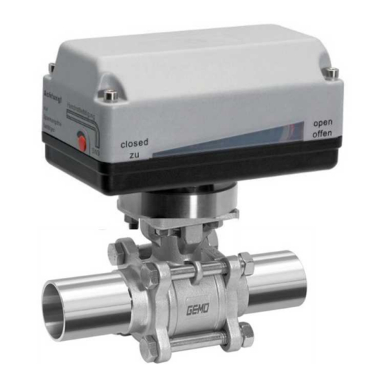
3.4 Description even automation components, can be clearly traced and read The GEMÜ B52 3-piece 2/2-way metal ball valve is motorized. using the CONEXO pen RFID reader. The CONEXO app, which It has a plastic actuator housing. A manual override and an can be installed on mobile devices, not only facilitates and im- optical position indicator are integrated as standard. -
Page 7: Correct Use
PTFE seals must always be anticipated. Despite this, the safety of the ball valve is not affected by any po- tential build-up of lint and the seal materials are compli- ant in accordance with FDA directives. www.gemu-group.com 7 / 55 GEMÜ B52... -
Page 8: Order Data
FTF EN 558 series 1, ISO 5752, Media wetted area cleaned to ensure suitability for paint 0101 basic series 1 applications, parts sealed in plastic bag Media wetted parts cleaned for high purity media and 0104 packed in plastic bag GEMÜ B52 8 / 55 www.gemu-group.com... - Page 9 7 Voltage/Frequency 24 VDC 8 Control module ON/OFF actuator 9 Actuator version 1015 Actuator, motorized, operating time 11s, torque 15Nm, GEMUE, size 1 supply voltage B1, C1 10 Type of design Standard 11 CONEXO Without www.gemu-group.com 9 / 55 GEMÜ B52...
-
Page 10: Ball Valve With J+J Actuator
J+J, type J4 basic series 1 heating, IP67 Actuator, motorized, operating time 29s, torque 85Nm, J4C85 5 Ball valve material Code J+J, type J4 1.4408 / CF8M (body, connection), 1.4401 / SS316 heating, IP67 (ball, shaft) GEMÜ B52 10 / 55 www.gemu-group.com... - Page 11 ON/OFF actuator, 2 additional potential-free limit switches, Class A (EN15714-2) 9 Actuator version J4C20 Actuator, motorized, operating time 10s, torque 20Nm, J+J, type J4 heating, IP67 10 Type of design Standard 11 CONEXO Without www.gemu-group.com 11 / 55 GEMÜ B52...
-
Page 12: Ball Valve Technical Data
80 100 120 140 160 180 200 Temperature TS [°C] Note media temperature Leakage rate: Leakage rate according to ANSI FCI70 – B16.104 Leakage rate according to EN12266, 6 bar air, leakage rate A GEMÜ B52 12 / 55 www.gemu-group.com... - Page 13 12.75 19.55 26.35 36.55 51.0 2½" 0.34 0.85 10.2 15.3 23.8 31.45 52.7 63.75 3" 0.425 1.02 11.9 19.55 28.05 39.1 55.25 69.7 4" 0.51 12.75 24.65 40.8 60.35 85.0 110.5 135.2 Kv values in m³/h www.gemu-group.com 13 / 55 GEMÜ B52...
- Page 14 0.425 1.445 5.95 11.9 23.8 40.8 59.5 90.1 136.0 185.3 3" 0.595 2.975 15.3 29.75 51.0 76.5 114.8 174.3 263.5 4" 0.85 2.975 13.6 34.0 63.75 106.3 161.5 250.8 375.7 569.5 Kv values in m³/h GEMÜ B52 14 / 55 www.gemu-group.com...
-
Page 15: Product Conformity
ATEX (2014/34/EU), order code Special version X ATEX marking: The ATEX marking of the product depends on the respective product configuration with valve body and actuator. It can be found in the product-specific ATEX documentation and the ATEX type plate. www.gemu-group.com 15 / 55 GEMÜ B52... -
Page 16: Mechanical Data
Valid for clean, non-particulate and oil-free media (water, alcohol, etc.), gas or saturated steam (clean and wet). PTFE seal. Weight: Ball valve Threaded Flange connection, spigot 1/4" 0.55 1.15 3/8" 0.55 1.15 1/2" 1.35 3/4" 1.45 1" 1¼" 1½" 2" 2½" 3" 11.7 14.7 4" 19.3 22.3 Weights in kg GEMÜ B52 16 / 55 www.gemu-group.com... -
Page 17: Technical Data Of Actuator
(code) (code B1) (code B4) 1006, 3006 A0, AE 1.20 1015, 3015 A0, AE 1.20 2070 00, 0E, 0P 2.60 4100 00, 0E, 0P 4.40 4200 00, 0E, 0P 3.60 Current data in A www.gemu-group.com 17 / 55 GEMÜ B52... -
Page 18: Bernard, J+J Actuators
Siemens 3RV 1011-1BA10 Set current 2.20 1.70 Current data in A GEMÜ 9468 Motor protection switch Siemens 3RV 1011-1FA10 type: Set current: 4.0 A 8.2 Bernard, J+J actuators Note: For technical data see manufacturer's original datasheets GEMÜ B52 18 / 55 www.gemu-group.com... -
Page 19: Dimensions
9.1.1.1 Actuator version 1006, 1015 80,0 145,0 80.0 145.0 40,0 62,0* 55,0 40.0 62.0 55.0 Actuator ver- sion 1006, 1015 94.0 49.0 Dimensions in mm 9.1.1.2 Actuator version 2070 121.5 121,5 83.5 83,5 40.0 235.0 Dimensions in mm www.gemu-group.com 19 / 55 GEMÜ B52... - Page 20 9 Dimensions 9.1.1.3 Actuator version 4100, 4200 207.0 277,5 277.5 131.0 Dimensions in mm 9.1.2 Bernard, AUMA, J+J actuators For more detailed information on third-party actuators, refer to the manufacturers' documentation GEMÜ B52 20 / 55 www.gemu-group.com...
- Page 21 3/4“ 36.0 42.0 1“ 42.0 50.0 11.0 1¼“ 42.0 50.0 11.0 1½“ 50.0 70.0 14.0 2“ 50.0 70.0 14.0 2½“ 50.0 70.0 14.0 3“ 70.0 102.0 17.0 4“ 70.0 102.0 17.0 Dimensions in mm www.gemu-group.com 21 / 55 GEMÜ B52...
- Page 22 290.0 81.0 104.5 90.0 4 x 18.0 76.0 200.0 160.0 18.0 310.0 96.0 107.0 108.0 10.0 8 x 18.0 100.0 220.0 180.0 18.0 350.0 124.0 113.0 123.0 10.0 8 x 18.0 Dimensions in mm GEMÜ B52 22 / 55 www.gemu-group.com...
- Page 23 24.0 2½“ 64.0 130.0 15.0 28.0 185.0 81.0 52.0 90.0 28.0 3“ 76.0 155.0 18.0 32.0 205.0 96.0 54.5 108.0 32.0 4“ 100.0 187.0 18.0 40.0 240.0 124.0 58.0 123.0 40.0 Dimensions in mm www.gemu-group.com 23 / 55 GEMÜ B52...
- Page 24 65.0 37.5 77.0 27.0 65.0 70.0 15.0 130.0 185.3 81.0 52.2 90.0 27.0 80.0 85.0 18.0 155.0 205.0 96.0 54.5 108.0 10.0 100.0 104.0 18.0 187.0 240.0 124.0 58.0 123.0 10.0 Dimensions in mm GEMÜ B52 24 / 55 www.gemu-group.com...
- Page 25 37.5 77.0 63.0 76.3 130.0 15.0 6.65 185.3 81.0 52.2 90.0 76.0 89.0 155.0 18.0 6.50 205.0 96.0 54.5 108.0 10.0 100.0 116.0 187.0 18.0 8.00 240.0 124.0 58.0 123.0 10.0 Dimensions in mm www.gemu-group.com 25 / 55 GEMÜ B52...
- Page 26 77.0 75.5 60.2 63.5 14.5 126.0 1.65 248.0 80.0 84.0 88.0 72.9 76.2 17.5 146.0 1.65 267.0 90.0 88.5 105.0 10.0 97.4 101.6 17.5 180.0 2.15 318.0 118.0 100.0 120.0 10.0 Dimensions in mm GEMÜ B52 26 / 55 www.gemu-group.com...
- Page 27 103.0 203.0 65.0 69.0 77.0 64.0 76.1 15.0 130.0 254.0 81.0 86.5 90.0 76.0 88.9 18.0 155.0 280.2 96.0 92.0 108.0 10.0 100.0 114.3 18.0 187.0 317.0 124.0 96.5 123.0 10.0 Dimensions in mm www.gemu-group.com 27 / 55 GEMÜ B52...
-
Page 28: Manufacturer's Information
Do not use the product as a step or a foothold. ● NOTICE Suitability of the product! ▶ The product must be appropriate for the piping system operating conditions (medium, medium concentration, temperature and pressure) and the prevailing ambient conditions. GEMÜ B52 28 / 55 www.gemu-group.com... -
Page 29: Installation With Butt Weld Spigots
14. Flow direction and installation position are optional. 2. Align the pipes 1 and 4 on the left and right with the butt weld spigots 2 and 3, and attach them to the spigots. www.gemu-group.com 29 / 55 GEMÜ B52... -
Page 30: Installation With Threaded Connections
Align the centre section 6 concentrically with butt weld spigots 2 and 3. 9. Tighten the nuts diagonally, counterhold with a wrench. Nominal size Torque [Nm] DN10 DN15 DN20 DN25 DN32 DN40 DN50 DN65 DN80 DN100 GEMÜ B52 30 / 55 www.gemu-group.com... -
Page 31: Installation With Flanged Connections
7. Insert bolts SN in all holes in the flange. 8. Slightly tighten the bolts SN and nuts M diagonally. 9. Check the alignment of the piping. 10. Tighten the nuts M diagonally. Observe appropriate regulations for connections! www.gemu-group.com 31 / 55 GEMÜ B52... -
Page 32: Electrical Connection
Change-over contact limit switch OPEN PE, protective earth conductor PE, protective earth conductor Connection diagram OPEN CLOSED Additional limit switches External wiring CLOSED-0-OPEN Connection assignment X1, UV Actuator CLOS Direction of travel CLOSED OPEN Direction of travel OPEN GEMÜ B52 32 / 55 www.gemu-group.com... - Page 33 L1, change-over (OPEN/CLOSED) N, change-over (OPEN/CLOSED) PE, protective earth conductor Preferred direction -OPEN- when all signals are present Connection diagram Limit switch OPEN External wiring Motor Limit switch CLOSED Actuator Direction of travel CLOSED OPEN www.gemu-group.com 33 / 55 GEMÜ B52...
- Page 34 Change-over contact limit switch OPEN PE, protective earth conductor PE, protective earth conductor Connection diagram OPEN CLOSED Additional limit switches External wiring CLOSED-0-OPEN Connection assignment X1, UV Actuator CLOS Direction of travel CLOSED OPEN Direction of travel OPEN GEMÜ B52 34 / 55 www.gemu-group.com...
- Page 35 PE, protective earth conductor PE, protective earth conductor Preferred direction -OPEN- when all signals are present Connection diagram OPEN CLOSED Additional limit switches External wiring L1 N Connection diagram X1, UV Actuator Direction of travel CLOSED OPEN www.gemu-group.com 35 / 55 GEMÜ B52...
-
Page 36: Connection And Wiring Diagram - Actuator Version 2070, 4100, 4200
The potential must be assigned by the user. When the OPEN and CLOSED switches are operated simultaneously the actuator "CLOSES". 12.2.1.1.3 Connection diagram Direction Motor protection switch switch recommended CLOSED L1/Uv+ External wiring OPEN N/Uv- Connection assignment X1 GEMÜ B52 36 / 55 www.gemu-group.com... - Page 37 When the OPEN and CLOSED switches are operated simultaneously the actuator "CLOSES". 12.2.1.2.3 Connection diagram OPEN CLOSED Motor protection switch Direction recommended switch Additional CLOSED limit switches L1/Uv+ External wiring OPEN N/Uv- Connection assignment X1 Connection assignment X2 www.gemu-group.com 37 / 55 GEMÜ B52...
- Page 38 When the OPEN and CLOSED switches are operated simultaneously the actuator "CLOSES". 12.2.1.3.3 Connection diagram Motor protection switch Direction Actual value potentiometer recommended switch CLOSED L1/Uv+ External wiring OPEN N/Uv- Connection assignment X1 Connection assignment X2 GEMÜ B52 38 / 55 www.gemu-group.com...
-
Page 39: Limit Switches
3. Undo screws 2. 4. Remove the cover of the actuator 3. 5. Undo the screws on the corresponding limit switch (4 = "CLOSED", 5 = "OPEN"). 6. Move limit switches to the desired position. 7. Tighten limit switch screws. www.gemu-group.com 39 / 55 GEMÜ B52... -
Page 40: Setting The Limit Switch For 2070, 4100, 4200
24 V DC, 24 V AC up to 250 V AC or operated directly via a PLC. - An electronic current limitation limits the torque. - For the above actuator types (except for code 2070), overall height 2 applies. GEMÜ B52 40 / 55 www.gemu-group.com... -
Page 41: Operation
To open the valve, turn the Allen key (SW3) clockwise 1 until the position indicator shows "open". To close the valve turn the Allen key (SW3) anti-clock- wise 2 until the position indicator shows "closed". OPEN CLOSED Reinsert red protective cap. www.gemu-group.com 41 / 55 GEMÜ B52... - Page 42 2. Insert crank handle and actuate the actuator by hand. Crank into the desired valve position (in the direction indic- ated on label): Actuator version 2070 Clockwise: OPEN Anticlockwise: CLOSED Actuator versions 4100, 4200 Clockwise: CLOSED Anticlockwise: OPEN GEMÜ B52 42 / 55 www.gemu-group.com...
-
Page 43: Troubleshooting
Flange bolting loose/thread leaking Retighten flange bolting / reseal threads Flange seals faulty Replace flange seals Valve body leaking Valve body faulty Check valve body for potential damage, replace valve body if necessary www.gemu-group.com 43 / 55 GEMÜ B52... -
Page 44: Inspection/Maintenance
Usually, retightening by between 30° and 60° will be sufficient to rectify the leakage. 17.1 General information regarding actuator replacement NOTICE The following tools are required for actuator replacement: Allen key ● GEMÜ B52 44 / 55 www.gemu-group.com... - Page 45 When ordering spare parts, specify the complete order ● number of the ball valve. 1. Remove the actuator (see chapter "Removing the actu- ator"). 2. Bend the tab 12 of the screw locking device downwards. www.gemu-group.com 45 / 55 GEMÜ B52...
- Page 46 7. Loosen the nuts 19 of the flange bolts 18 of the ball valve and remove with washers 20. 8. Remove the flange bolts 18. 9. Remove the centre section KM. 13. Carefully press the spindle 7 into the body and remove. GEMÜ B52 46 / 55 www.gemu-group.com...
- Page 47 15. Remove O-ring 23 from spindle 7. NOTICE ▶ O-ring 23 is not available for connection type spigot ASME BPE code 59. 16. Remove seal 6 from spindle 7. 17. Mount the seals and the ball valve in reverse order. www.gemu-group.com 47 / 55 GEMÜ B52...
-
Page 48: Spare Parts
Order designation Ball valve body assembly BB02… Body seal Seat and flange seal Conical spindle seal BB02 DN...SDS D60 5 V-ring spindle packing O-ring Actuator See actuator designation. Depend- ent on the actuator version. GEMÜ B52 48 / 55 www.gemu-group.com... - Page 49 Order designation Ball valve body assembly BB02 Body seal Seat and flange seal Conical spindle seal BB02 DN...SDS D59 5 V-ring spindle packing O-ring Actuator See actuator designation. Depend- ent on the actuator version. www.gemu-group.com 49 / 55 GEMÜ B52...
-
Page 50: Removal From Piping
1. Clean the product. 2. Request a return delivery note from GEMÜ. 3. Complete the return delivery note. 4. Send the product with a completed return delivery note to GEMÜ. GEMÜ B52 50 / 55 www.gemu-group.com... -
Page 51: Eu Declaration Of Incorporation According To The Ec Machinery Directive 2006/42/Ec, Annex Ii B
Annex I of the above-mentioned Directive. Machinery Directive texts Product: GEMÜ B52 Product name: Motorized ball valve The following essential health and safety 1.1.2.;... -
Page 52: Eu Declaration Of Conformity In Accordance With 2014/68/Eu (Pressure Equipment Directive)
74653 Ingelfingen-Criesbach, Germany hereby declare under our sole responsibility that the below-mentioned product complies with the regulations of the above-men- tioned Directive. PED texts Product: GEMÜ B52 Product name: Motorized ball valve Notified body: TÜV Rheinland Industrie Service GmbH Am Grauen Stein 1... -
Page 53: Eu Declaration Of Conformity In Accordance With 2014/30/Eu (Emc Directive)
74653 Ingelfingen-Criesbach, Germany hereby declare under our sole responsibility that the below-mentioned product complies with the regulations of the above-men- tioned Directive. EMC texts Product: GEMÜ B52 Product name: Motorized ball valve The following harmonized standards (or EN 61000-6-4:2007/A1:2011 parts thereof) have been applied: M. -
Page 54: Eu Declaration Of Conformity In Accordance With 2014/35/Eu (Low Voltage Directive)
Directive. LVD texts Product: GEMÜ B52 Product name: Motorized ball valve Product version: Valid for product versions with GEMÜ type 9428 and 9468 actuators The following harmonized standards (or EN IEC 61010-2-201:2018;... - Page 55 GEMÜ Gebr. Müller Apparatebau GmbH & Co. KG Fritz-Müller-Straße 6-8, 74653 Ingelfingen-Criesbach, Germany Subject to alteration Phone +49 (0) 7940 1230 · info@gemue.de www.gemu-group.com 03.2023 | 88735965...
Need help?
Do you have a question about the B52 and is the answer not in the manual?
Questions and answers