
Summary of Contents for PureTools PT-IP-CNTRL10
- Page 1 User Manual PT-IP-CNTRL10 User Manual AV over IP Network Interface for PT-IP-HD-26x Series PT- IP-CNTRL10 Model Designed in Germany V1.0 © 2022 PureLink GmbH All rights reserved.
- Page 2 User Manual PT-IP-CNTRL10 Preface Read this user manual carefully before using this product. Pictures shown in this manual are for reference only. Different model layouts and specifications are subject to the physical product. This manual is for operation instructions only, not for any maintenance usage.
- Page 3 PT-IP-CNTRL10 REACH | 1907/2006/EU ROHS | 2011/65/EU PureLink hereby declares that this product PureTools PT-IP-CNTRL10 complies with Directives 1907/2006/EU und 2011/65/EU. EMC / LVD (Electro Magnetic Compatibility / Low Voltage Directive) PureLink GmbH hereby declares that this product PureTools PT- IP-CNTRL10 complies with Directives 2014/30/EU and 2014/35/EU.
- Page 4 User Manual PT-IP-CNTRL10 SAFETY PRECAUTIONS To ensure the best from the product, please read all instructions carefully before using the device. Save this manual for further reference. Unpack the equipment carefully and save the original box and packing material ...
-
Page 5: Table Of Contents
User Manual PT-IP-CNTRL10 Content 1. Product Introduction......................1.1 Introduction........................1.2 Features..........................1.3 Package List........................2. Panel Description......................... 2.1 Encoder Panel......................... 2.2 Decoder Panel........................ 2.3 IR Pin Definition......................3. Specification.......................... 4. System Diagram........................5. Rack Mounting Instruction....................5.1 6U Rack Mounting...................... -
Page 6: Product Introduction
User Manual PT-IP-CNTRL10 1. Product Introduction 1.1 Introduction This Video over IP Controller is used to control and manage H.264/H.265 IP products. It supports dual 100M network ports, which can realize dual network isolation of Control network and Multicast video distribution network. Built-in Web GUI, TCP and RS-232 control are supported. -
Page 7: Package List
User Manual PT-IP-CNTRL10 1.3 Package List • 1 x Video over IP Controller • 1 x 20kHz-60kHz 12V IR Receiver Cable (1.5 meters) • 1 x 3-pin 3.81mm Phoenix Connector (Male) • 1 x 6-pin 3.81mm Phoenix Connector (Male) •... -
Page 8: Decoder Panel
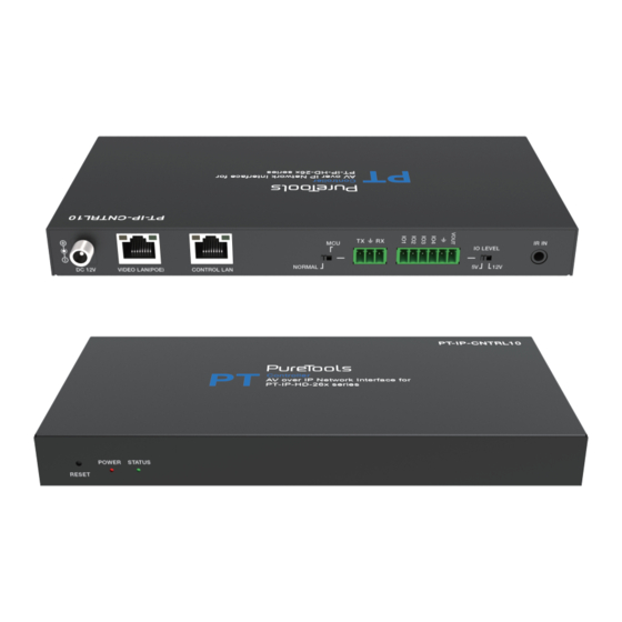
User Manual PT-IP-CNTRL10 2.2 Decoder Panel IR IN IO LEVEL NORMAL DC 12V Name Description DC 12V DC 12V/1A power input port. 100M Video LAN port, supporting POE function. VIDEO LAN Note: When POE is enabled, DC 12V/1A power supply is (POE) not required. -
Page 9: Ir Pin Definition
User Manual PT-IP-CNTRL10 2.3 IR Pin Definition IR RECEIVER IR Signal Grounding Power 12V IR RECEIVER 3. Specification Technical Network Bandwidth 100M Transmission 100m CAT 5E/6/6A/7 Distance 2 x 100M LAN [RJ45 connector] [VIDEO LAN support POE] 1 x IR IN [3.5mm audio jack, 12V level] Control Ports 1 x DIGITAL I/O [6-pin 3.81mm phoenix connector]... -
Page 10: System Diagram
User Manual PT-IP-CNTRL10 4. System Diagram Usage Precaution • Make sure all components and accessories included before installation. • System should be installed in a clean environment with proper temperature and humidity. • All of the power switches, plugs, sockets, and power cords should be insulated and safe. -
Page 11: Rack Mounting Instruction
User Manual PT-IP-CNTRL10 Notes: (1) For the default IP mode of Control LAN port of the Controller Box is DHCP, the PC also needs to be set to “Obtain an IP address automatically” mode, and an optional DHCP server (e.g. network router) is recommended in the system. - Page 12 User Manual PT-IP-CNTRL10 Step 2: Insert the product with mounting ears into a 6U rack (up to 10 units can be installed vertically), as shown in the figure below: Step 3: Use screws to fix mounting ears on the rack to complete the mounting, as...
-
Page 13: Rack Mounting
User Manual PT-IP-CNTRL10 5.2 1U Rack Mounting This product also can be mounted in a standard 1U rack (up to 4 units can be installed horizontally). The mounting steps are as follows: Step 1: Stack two products on top of each other, then use included screws to fix two 1U rack panels on the products, as shown in the figure below:... -
Page 14: Web Gui User Guide
User Manual PT-IP-CNTRL10 6. Web GUI User Guide 6.1 Preparation before Entering the System You can use the built-in Web GUI to control all IP products at the Switch. The operation method is shown as below. Step 1: Input the Controller’s default IP address (192.168.0.225) or the URL (http:// controller.local) into the Web browser address bar on the PC to enter the Web GUI... - Page 15 User Manual PT-IP-CNTRL10 Step 3: Select “Automatically managed by Controller Box” as the IP mode of Video LAN. (The other two modes are reserved items and are not currently available.) Then, please connect all the devices according to the following diagram.
- Page 16 User Manual PT-IP-CNTRL10 Step 4: Click the “Next” button and wait for the completion to enter the interface as shown in the figure below. ▪ If you select “Automatically add Encoders and Decoders to project”, and click the “Scan” button to enter the Project page. All the connected devices will be listed in the Current Devices list.
- Page 17 User Manual PT-IP-CNTRL10 After scanning is complete, the “Assign” buttons behind Unassigned Encoders and Unassigned Decoders in the figure below will become operable. At this time, you can click the “Assign” button behind each unregistered Encoder or Decoder to add the device to the project one by one.
-
Page 18: Functions And Operation
User Manual PT-IP-CNTRL10 6.2 Functions and Operation ■ Preview Page On this page, you can preview the Encoder/Decoder by clicking the drop down list on the right side. ■ Matrix Control Page Encoders: Display all the current Encoders. The text in the figure is the name of ①... - Page 19 User Manual PT-IP-CNTRL10 Operating Instructions: (1) If an Encoder shows “No Signal”, it means that the Encoder cannot be dragged. (2) If there is an image on an Encoder, it means that the Encoder can be dragged. As shown in the figure above, if an Encoder is dragged to the place where the red arrow points to, all Decoders will share the same signal resource from this Encoder;...
- Page 20 User Manual PT-IP-CNTRL10 (7) Click “Assign New Devices” to search new devices automatically and add to the current project. Encoders Page ■ The ID of the current device. (Note: ID is not duplicated.) ① Name: The name of the current device. (Note: Name is not duplicated.) ②...
- Page 21 User Manual PT-IP-CNTRL10 On this page, you can setup the current Encoder as required.
- Page 22 User Manual PT-IP-CNTRL10 ■ Decoders Page The ID of the current device. (Note: ID is not duplicated.) ① Name: The name of the current device. (Note: Name is not duplicated.) ② MAC Address: The MAC Address of the current device.
- Page 23 User Manual PT-IP-CNTRL10 On this page, you can setup the current Decoder as required.
- Page 24 User Manual PT-IP-CNTRL10 Locked Signal Routing Page ■ On this page, you can independently route the different signals between Encoder & Decoder devices. Please click “Locked Routing Help” for details. ■ Video Wall Management Page On this page, you can create and configure video wall as required. Please follow below steps to create a video wall.
- Page 25 User Manual PT-IP-CNTRL10 You can set the Video Wall ID, Name, Horizontal and Vertical panel numbers. Then click “Create” to create the Video Wall. Note: Up to 9 video walls can be created. Step 2: Select the video wall that you want to configure on the “Video Wall List”, then click “Assign Decoder”...
- Page 26 User Manual PT-IP-CNTRL10 Step 3: Click “Class Configuration” to enter the class configuration page, then click each screen to select the corresponding Class as required (the same class name will form a video wall, you can create a regular or irregular video wall by Class Configuration).
- Page 27 User Manual PT-IP-CNTRL10 On this page, you can select different video walls and configurations that you have set up by clicking the drop-down box on the right of “Video Wall Selection / Configuration Selection”. Besides, you can directly drag Encoders at the top of the page to the video wall to change signal sources.
- Page 28 User Manual PT-IP-CNTRL10 ■ Users Page On this page, you can add new user accounts with their own control privileges. This will allow you to create a unique login and limit features such as inputs and outputs that each person has access to.
- Page 29 User Manual PT-IP-CNTRL10 ① General Settings: The basic settings of the Controller. ② Control Network: The network port configuration of the Controller connected to the Switch. ③ Video Network: The network port configuration of the Controller connected to video source devices.
- Page 30 User Manual PT-IP-CNTRL10 ■ Password Update Page On this page, you can change the password. Note that after changing, it will skip to the Web browser home page or the Web GUI login interface automatically. You need to log in the Web GUI again with the new password.
-
Page 31: After-Sales Service
User Manual PT-IP-CNTRL10 7. After-Sales Service If there appear some problems when running the product, please check and deal with the problems referring to this user manual. Any transport costs are borne by the users during the warranty. 1) Product Limited Warranty: This product will be free from defects in materials and workmanship for three years (The purchase invoice shall prevail). - Page 32 User Manual PT-IP-CNTRL10...
-
Page 33: Asking For Assistance
User Manual PT-IP-CNTRL10 Asking for Assistance Technical Support: Phone: +49 5971 800299 - 0 Fax: +49 5971 800299 – 99 Technical Support Hours: 8:30 AM to 5:00 PM Monday thru Thursday 8:30 AM to 4:00 PM Friday Write to: PureLink GmbH Von-Liebig-Straße 10...
Need help?
Do you have a question about the PT-IP-CNTRL10 and is the answer not in the manual?
Questions and answers