Table of Contents
Advertisement
Quick Links
Advertisement
Table of Contents

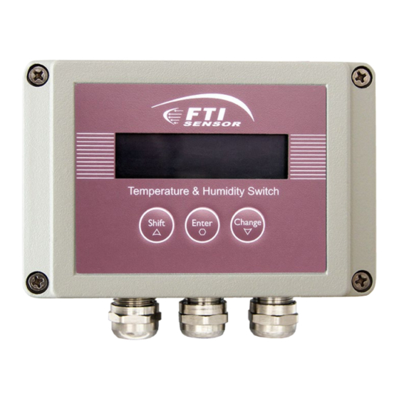
Summary of Contents for FTI TB750 Series
- Page 1 User’s Manual TB750 series FTI Technology Inc www.ftisensors.com...
- Page 2 This switch is intrinsically safe type. It is designed and manufactured in accordance with standards "GB3836.1-2010 "Explosive atmospheres - Part 1: General requirements for equipment", "GB3836.4-2010 "Explosive atmospheres Part 4: Equipment protected by intrinsically safe ", and "Q/FTI01-2017 "TB750 series switch controller" enterprise standards. Parameters...
- Page 3 Temperature and Humidity Switch TB750 series Dimensional drawing Electrical connection Installation and operation TB750 Intrinsically safe wiring diagram...
- Page 4 Temperature and Humidity Switch TB750 series Fixation and installation This product should be fixed and installed on the wall or other suitable surfaces by mounting brackets, typically on a vertical wall. M4 screws are recommended for fixation. The mounting size of the bracket-fixing hole is 122mm×116mm.
- Page 5 Temperature and Humidity Switch TB750 series Debugging and settings Overview of parameter settings The initial state of the controller after power-on is defined as "General state". The state of entering the menu operation and setting parameters is defined as “Setting state”.
- Page 6 Temperature and Humidity Switch TB750 series Humidity switch control parameters: KhA, KhB, KhDelay and KhType Corresponding menus: Kh-A, Kh-B, Kh-Delay and Kh-Type These 4 parameters are used for the control setting of the humidity switch. Please refer to the temperature switch control parameters for functions.
- Page 7 Temperature and Humidity Switch TB750 series Product maintenance If there are problems during installation and use, please contact our company in time and do not open and repair without authorization. The connection must be done strictly according to the "wiring diagram" to prevent damage to the product.
- Page 8 FTI Technology,Inc 8930S.Beck Avenue,Ste107Tempe,Arizo na 85284 USA E-mail:sales@Ftisensors.com www.Ftisensors.com V0.0.0.221124...
Need help?
Do you have a question about the TB750 Series and is the answer not in the manual?
Questions and answers