Table of Contents
Advertisement
Quick Links
Advertisement
Table of Contents

Related Manuals for BLEMO SH61

Summary of Contents for BLEMO SH61
- Page 1 ® BLEMO Soft Starter SH61 User Manual...
- Page 2 Legal Information The BLEMO® brand and any trademarks of BLEMO and its subsidiaries referred ® to in this guide are the property of BLEMO or its subsidiaries. All other brands may ® be trademarks of their respective owners. This guide and its content are protected under applicable copyright laws and furnished for informational use only.
-
Page 3: Table Of Contents
Mounting Position ....................24 Soft Starter Cooling and Power Dissipation ............25 Dimensions ........................ 26 Installing Door Mounting Kit ..................30 Protective Covers For SH61-220/6...-630/6 ............31 Fieldbus Modules ...................... 33 Wiring ......................Power Terminals ....................... 36 Power Connections SH61-7.5/6...SH61-55.0/6 ..........36 Power Connections SH61-75.0/6...SH61-630/6 .......... - Page 4 SH61 Security Policy ..................70 Potential Risks and Compensating Controls ..........72 Data Flow Restriction ..................73 Initial Setup ........................ 73 Password ........................73 Security Event Logging .................... 74 Upgrades Management ................... 75 Clear Device / Secure Decommissioning .............. 76 Commissioning ..................
- Page 5 4.1 [DI3 assignment] 4.2 [DI4 assignment] .......176 4.3 [DQ1 configuration] .................177 4.4 [DQ2 Configuration] ................178 4.5 [AI1 configuration] ................179 4.6 [AQ1 configuration] .................180 4.7 [R1 configuration] ................183 4.9 [R3 configuration] ................184 5 [2nd Mot Parameters] ................186 6 [Communication] ..................192 6.1 [Modbus Fieldbus] ................193 6.2 [Modbus HMI] MD2..................197 6.3 [Eth Module Config]...
- Page 6 Environment Data ....................274 Electrical Data ......................274 Mains Supply in Function of the System Earthing Arrangement According to the Altitude ................. 274 Normal Duty, Soft Starter In Line Connection, 208. 690 Vac 50/60 Hz Supply ....................... 275 Normal Duty, Soft Starter Inside Delta Connection, 230. 415 Vac 50/ 60 Hz Supply ....................
-
Page 7: Safety Information
CAUTION NOTICE Please Note Electrical equipment should be installed, operated, serviced, and maintained only by qualified personnel. No responsibility is assumed by BLEMO ® for any consequences arising out of the use of this material. A qualified person is one who has skills and knowledge related to the construction and operation of electrical equipment and its installation, and has received safety training to recognize and avoid the hazards involved. -
Page 8: Qualification Of Personnel
Safety Information Qualification of Personnel Only appropriately trained persons who are familiar with and understand the contents of this manual and all other pertinent product documentation are authorized to work on and with this product. In addition, these persons must have received safety training to recognize and avoid hazards involved. - Page 9 ELECTRIC SHOCK OR UNANTICIPATED EQUIPMENT OPERATION Do not use damaged products or accessories. Failure to follow these instructions will result in death or serious injury. Contact your local BLEMO ® sales office if you detect any damage whatsoever. This equipment has been designed to operate outside of any hazardous location.
- Page 10 Safety Information Your application consists of a whole range of different interrelated mechanical, electrical, and electronic components, the soft starter being just one part of the application. The soft starter by itself is neither intended to nor capable of providing the entire functionality to meet all safety-related requirements that apply to your application.
- Page 11 IT security and cyber security (such as: ISO/IEC 27000 series, Common Criteria for Information Technology Security Evaluation, ISO/ IEC 15408, IEC 62351, ISA/IEC 62443, NIST Cybersecurity Framework, Information Security Forum - Standard of Good Practice for Information Security, BLEMO ® recommended Cybersecurity Best Practices*). •...
- Page 12 • The references from SH61-7.5/6 to SH61-55.0/6 can be adapted to a domestic environment (B environment) by adding an external bypass contactor. For other SH61 references, you must consider other mitigation measures.
-
Page 13: About The Book
About the Book Document scope The purpose of this document is: • to give you mechanical and electrical information related to the SH61. • to show you how to install, wire and program this soft starter. Validity note Original instructions and information given in the present document have been written in English (before optional translation). -
Page 14: Related Documents
About the Book Related Documents Use your tablet or your PC to quickly access detailed and comprehensive information on all our products on https://www.blemo.com The Internet site provides the information you need for products and solutions: • The whole catalog for detailed characteristics and selection guides •... -
Page 15: Electronic Product Data Sheet
About the Book Catalog number Title of documentation Video: How to update the firmware on SH61 with (English) EcoStruxure Automation Device Maintenance? Recommended Cybersecurity Best Practices CS-Best-Practices (English) Video: How to configure the cybersecurity applied to (English) SH61? You can download there technical publications and other technical information from our website at https://www.blemo.com. -
Page 16: Software Enhancements
Also see the glossary at the end of this manual. Software Enhancements Overview The BLEMO ® Soft Starter SH61 will benefit from future software enhancements. Those enhancements will be listed below. This documentation relates to the version V1.1. V1.1 Release Note Initial release... -
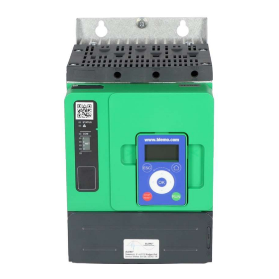
Page 17: Soft Starter Overview
Soft Starter Overview Soft Starter Overview SH61-7.5/6...SH61-22.0/6 SH61-30.0/6...SH61-55.0/6 3–phase 208...690 V, 17...47 A, 3–phase 208...690 V, 62...110 A, 2.2...45 kW, 3...50 HP 11...90 kW, 15...125 HP Frame size A Frame size B SH61-75.0/6...SH61-90.0/6 SH61-110/6...SH61-160/6 3–phase 208...690 V, 140...170 A, 3–phase 208...690 V, 210...320 A, 30...160 kW, 40...200 HP... - Page 18 Soft Starter Overview SH61-220/6...SH61-355/6 SH61-400/6...SH61-630/6 3–phase 208...690 V, 410...660 A, 3–phase 208...690 V, 790...1200 A, 90...630 kW, 125...850 HP 220...900 kW, 250...1200 HP Frame size E Frame size F Manufacturing Date Use the serial number on the nameplate of the soft starter to retrieve its manufacturing date.
-
Page 19: Inspect, Store And Handle The Product
DANGER ELECTRIC SHOCK OR UNANTICIPATED EQUIPMENT OPERATION Do not use damaged products or accessories. Failure to follow these instructions will result in death or serious injury. Contact your local BLEMO ® sales office if you detect any damage whatsoever. Step... - Page 20 Inspect, Store and Handle the Product If the SH61 must be shipped to another location, use the original shipping material. WARNING INCORRECT HANDLING • Follow all handling instructions provided in this manual and in all associated product documentation. • Handle and store the product in its original packaging.
-
Page 21: Installation
SH61-400/6...-630/6 115 (253.5) Pallet Unpacking and Hoisting the References on Pallet The references from SH61-110/6 to SH61-630/6 are mounted on pallet. CAUTION SHARP EDGES Use all necessary personal protective equipment (PPE) such as gloves when removing the components from the pallet. -
Page 22: Soft Starter Mounting
Installation See the procedure for hoisting the references from SH61-220/6 to SH61-630/6: Step Action Lift the soft starter by means of a hoist by using the handling lugs of the soft starter to fasten the lifting equipment. The lifting bar is not supplied. -
Page 23: Mounting In An Enclosure
IP54 / NEMA12 θi θe θi θe θe θi θe = external ambient SH61 SH61 temperature SH61 θi = internal ambient temperature of the enclosure Do not use insulated or non- metallic enclosures as they have poor thermal conduction. -
Page 24: Mounting Position
Installation Mounting Position The soft starter is designed to be mounted inside cabinets vertically at ± 10° for cooling purposes. Respect the minimum clearances so that the cooling air can circulate from the bottom to the top of the soft starter. The minimum clearances apply to any device close to the soft starter such as circuit breakers, fuses, contactors, bypass contactors. -
Page 25: Soft Starter Cooling And Power Dissipation
Power Dissipated at Minimum air flow rate Size Nominal Load in Normal Heavy Load in Normal required Duty, not Bypassed (W) Duty, not Bypassed (W) m³/hour ft³/min SH61-7.5/6 No fan SH61-11.0/6 No fan SH61-15.0/6 SH61-18.5/6 SH61-22.0/6 SH61-30.0/6 SH61-37.0/6 SH61-45.0/6 SH61-55.0/6 SH61-75.0/6... -
Page 26: Dimensions
Dimensions Use screws with DIN 125 washer to mount the soft starter. Tighten the fixing screws. BLEMO ® Soft Starter SH61 CAD files can be downloaded from https://www.blemo.com. SH61-7.5/6...SH61-22.0/6 Front, Side and Rear View, frame size A 0.27 Mounting screws x 4: M6 SH61-30.0/6...SH61-55.0/6... - Page 27 Installation SH61-75.0/6...SH61-90.0/6 Front, Side and Rear View, frame size C 10.7 Ø7 0.27 Ø7 0.27 Mounting screws x 4: M6 SH61-110/6...SH61-160/6 Front, Side and Rear View, frame size D 12.6 Mounting screws x 4: M8 01/2023...
- Page 28 Installation SH61-220/6...SH61-355/6 Front, Side and Rear View, frame size E Mounting screws x 4: M8 01/2023...
- Page 29 Installation SH61-400/6...SH61-630/6 Front, Side and Rear View, frame size F Mounting screws x 6: M10 01/2023...
-
Page 30: Installing Door Mounting Kit
Installation Installing Door Mounting Kit The SH61 is delivered with the Plain Text Display Terminal. The Graphic Display Terminal is available as an option to replace the Plain Text Display Terminal. Door mounting kits are available as options to mount the display terminal on the door of the enclosure. -
Page 31: Protective Covers For Sh61-220/6
M6 fixing screws • Maximum 5 mm (0,2 inch) thick • Same width as the soft starter: ◦ 400 mm (15,7 inches) for SH61-220/6...SH61-355/6 ◦ 770 mm (30;3 inches) for SH61-400/6...SH61-630/6 • Maximum length below and above the soft starter: ◦... - Page 32 Installation The following measurements are in millimeters (inches). SH61-220/6... SH61-355/6 SH61-400/6... SH61-630/6 188,5 188,5 (0.55) (7.4) (7.4) (1.7) (13.6) (13.6) 3xM6 3xM6 3xM6 3xM6 01/2023...
-
Page 33: Fieldbus Modules
Installation Fieldbus Modules Fieldbus Modules can be used with the soft starter for communicating with the product, applying commands and monitoring. For the list of Fieldbus Manuals refer to Related Documents, page 01/2023... -
Page 34: Wiring
Wiring Wiring General instructions DANGER HAZARD OF ELECTRIC SHOCK, EXPLOSION OR ARC FLASH Read and understand the instructions in Safety Information chapter before performing any procedure in this chapter. Failure to follow these instructions will result in death or serious injury. DANGER HAZARD OF FIRE OR ELECTRIC SHOCK Wire cross sections and tightening torques must comply with the... - Page 35 Wiring Product may perform unexpected movements because of incorrect wiring, incorrect settings, incorrect data or other errors. WARNING UNANTICIPATED EQUIPMENT OPERATION • Carefully install the wiring in accordance with the EMC requirements. • Do not operate the product with unknown or unsuitable settings or data. •...
-
Page 36: Power Terminals
Wiring Power Terminals Power Connections SH61-7.5/6...SH61-55.0/6 Mains side Motor side (bottom) Use class C cables for the power connections. • 1/L1, 3/L2, 5/L3: Mains supply inputs • 2/T1, 4/T2, 6/T3: Outputs to motor • A2, B2, C2: Soft starter bypass... - Page 37 IP protection degree is IP10. (b) The cross section cable values are given for one cable per cages. The good behavior of the SH61 is not assured with more than one cable per cages. 01/2023...
-
Page 38: Power Connections Sh61-75.0/6
(AWG) N.m (lbf.in) SH61-7.5/6...-22.0/6 10 (10) 1.7 (15) SH61-30.0/6...-55.0/6 16 (6) 3 (26) Power Connections SH61-75.0/6...SH61-630/6 Mains side Motor side (bottom) 1/L1 3/L2 5/L3 NOTE: Do not access the power bars when the supply mains is On. NOTE: Do not access the power bars when the supply mains is On. - Page 39 Section Tightening torque fraction of the soft mm² (AWG) N.m (lbf.in) starter mm (in) mm (in) mm (in) rating) SH61-75.0/6 16 (6) 34 (300) 20 (0.8) 5 (0.2) 9 (0.3) 50 (1/0) 95 (3/0) SH61-90.0/6 25 (4) 70 (2/0) 95 (4/0)
- Page 40 Section Tightening torque fraction of the soft mm² (AWG) N.m (lbf.in) starter mm (in) mm (in) mm (in) rating) SH61-400/6 185 (400 kcmil) 57 (500) 60 (2.3) 5 (0.2) 14 (0.5) 2x240 (3x300 kcmil) Cu bar 2x (80x5mm) (2.5x0.25”) 2x150 (2x250...
- Page 41 Wiring The use of aluminum field wiring cables is allowed on SH61 from SH61-75.0/6 to SH61-630/6 with limitation. In case of usage of terminal protection kits, the cross section of aluminum cable may be incompatible with the protection kit capacity and can cause equipment damage or impossible mounting.
-
Page 42: Connection Of The Motor And Supply Mains
Wiring Connection Of The Motor and Supply Mains Connection In-Line The soft starter can be connected in–line to the motor supply. The motor connection type (star/delta) depends on the supply mains, refer to the motor nameplate. • (a): Supply mains •... - Page 43 195A, i.e. SH61-110/6 (210A) for a normal duty application. • Inside delta connection: the current in each winding is equal to 195/√3 = 114A, SH61-75.0/6 is sufficient for this normal duty application. • (a): Supply mains •...
-
Page 44: Control Terminals
Wiring Control Terminals DANGER HAZARD OF FIRE OR ELECTRIC SHOCK Wire cross sections and tightening torques must comply with the specifications provided in this document. If you use flexible multi-wire cables for a connection with a voltage higher than 25 Vac, you must use ring type cable lugs or wire ferrules, depending on the wire gauge and the specified stripping length of the cable. -
Page 45: Control Block Wiring Diagram
INCORRECT VOLTAGE Supply the control supply terminals CL1 / CL2 within a range of 110...230 Vac only In case of migration from SH61●●●, adapt the control supply transformer Failure to follow these instructions can result in equipment damage. Tightening Min relay output... -
Page 46: Control Terminal Characteristics
RUN and STOP Management, page The SH61 control part can be supplied by the +24 terminal, allowing to keep the communication with the soft starter but with no possibilities to control the motor. To control the motor, the SH61 must be supplied in 110...230 Vac via the terminals CL1 and CL2. -
Page 47: Run And Stop Management
Wiring Terminals Function Characteristics Digital output supply • 24 Vdc digital output supply Programmable digital output 1 • 2 open collector outputs compatible with level 1 PLC, IEC 65A-68 standard. Programmable digital output 2 • Power supply +24 Vdc (min. 12 Vdc, max 30 Vdc) •... - Page 48 Wiring 3–wire control Run and Stop are controlled by 2 different digital inputs. The Stop order is applied at low level on the Stop terminal. The Run order is applied at high level on the Run terminal only if Stop terminal is at high level.
-
Page 49: Relay Contacts Wiring
® RC device. Refer to the Motor control and protection components catalog available on https://www.blemo.com to find the RC device to be associated with the contactor used. Example: With a 48 Vac source, contactors have to be used with voltage suppression device. - Page 50 SH61 (1) DC 30 Vdc maximum. (2) TVS diode BLEMO ® contactors with DC coil include the TVS diode. No additional device is required. Refer to the Motor control and protection components catalog available on https://www.blemo.com for more information. 01/2023...
- Page 51 Wiring Other Inductive DC Loads Other inductive DC loads without embedded TVS diode must use one of the following voltage suppression device: • A bidirectional TVS device as shown on the drawing above, defined by: ◦ TVS break-down voltage greater than 35 Vdc, ◦...
-
Page 52: Application Diagrams
Line contactor controlled by Power ON and Power OFF push-buttons or on detected error This application diagram is well adapted to local control using inputs of SH61. It requires a local intervention to restart after the error reset even in case of remote control: press S3 push button to restart. Use relay output R1 set to [Operating State Fault] (factory setting) to turn Off the soft starter when an error is detected. - Page 53 Coordination, 2-wire control Line contactor controlled based on RUN & STOP or on detected error. Freewheel stop only. Simplified application diagram for local control using inputs of SH61. Use relay output R1 set to [Isolating Relay] to turn Off the soft ISOL starter when an error is detected or on STOP command.
- Page 54 Wiring Designation Component Description Circuit breaker Short circuit protection device for the control part of the soft starter Contactor Line contactor Emergency Stop push-button Emergency Stop to de-energized KM1 line contactor Normally close push-button Power OFF and freewheel stop Normally open push-button Power ON and Run order Connection In Line, With Line and Bypass Contactor, Freewheel Or Controlled Stop, Type 1 or 2 Coordination, 2-wire or 3-wire...
- Page 55 Wiring Designation Component Description Contactor Line contactor Emergency Stop push-button Emergency Stop to de-energized KM1 line contactor Normally close push-button Power OFF Normally open push-button Power ON Normally close contact push-button STOP command for 3-wire control and Power OFF Normally open contact push-button. RUN command for 3-wire control and Power On Selector switch, 2 positions, stay RUN/STOP.
- Page 56 Wiring Circuit breaker Short circuit protection device for the secondary of the transformer Circuit breaker Short circuit protection device for the control part of the soft starter Contactor Line contactor Emergency Stop push-button Emergency Stop to de-energized KM1 line contactor Normally close contact push-button STOP command for 3-wire control Normally open contact push-button.
- Page 57 Wiring Circuit breaker Short circuit protection device for the secondary of the transformer Circuit breaker Short circuit protection device for the control part of the soft starter Contactor Line contactor Emergency Stop push-button Emergency Stop to de-energized KM1 line contactor Normally close push-button Power OFF Normally close push-button...
- Page 58 Wiring Designation Component Description Fast acting fuses Short circuit protection device of the soft starter to be used only when type 2 coordination Circuit breaker Short circuit protection device for the secondary of the transformer Circuit breaker Short circuit protection device for the control part of the soft starter Contactor Line contactor Emergency Stop push-button...
- Page 59 Wiring Connection to a Two Speeds Motor With Two Sets of Parameters, Line and Bypass Contactor, Type 1 or 2 Coordination, 2-wire Control Line contactor controlled based on RUN and STOP command or detected error Use relay output R1 set to [Isolating Relay] ISOL.to turn Off the soft starter when an error is detected or on STOP command. Set DI3 to [2nd Mot Param Set] LIS.
-
Page 60: Upstream Protection Devices
NOTE: Use of an SCPD not in compliance with the manufacturer's recommendations can invalidate the co-ordination. Refer to the BLEMO Catalogue to select the appropriate coordination components. ® 01/2023... -
Page 61: Checking Installation
Checking Installation Checking Installation Check List: Before Switching On Unsuitable settings or unsuitable data or unsuitable wiring may trigger unintended movements, trigger signals, damage parts and disable monitoring functions. WARNING UNANTICIPATED EQUIPMENT OPERATION • Only start the system if there are no persons or obstructions in the zone of operation. - Page 62 Do all fuses and circuit breaker have the correct rating; are the fuses of the specified type? Refer to the information provided in the BLEMO Soft Starter SH61 Catalog. See Related Documents, page Did you connect or insulate all wires at the cable ends?
-
Page 63: Cybersecurity
The objective of Cybersecurity is to help provide increased levels of protection for information and physical assets from theft, corruption, misuse, or accidents while maintaining access for their intended users. No single Cybersecurity approach is adequate. BLEMO ® recommends a defense- in-depth approach. - Page 64 IT security and cyber security (such as: ISO/IEC 27000 series, Common Criteria for Information Technology Security Evaluation, ISO/ IEC 15408, IEC 62351, ISA/IEC 62443, NIST Cybersecurity Framework, Information Security Forum - Standard of Good Practice for Information Security, BLEMO ® recommended Cybersecurity Best Practices*).
- Page 65 • Firmware upgrades – the SH61 upgrades are implemented consistently to the current version of firmware available on https://www.blemo.com. • Controls against malware – detection, prevention, and recovery controls to help protect against malware are implemented and combined with appropriate user awareness.
-
Page 66: Security Policy
These should be known by the users. The anti-intrusion and anti-physical access to any sensitive installation should be set up. All the security rules implemented in the SH61 are in complement of the points above. 01/2023... -
Page 67: Product Defense-In-Depth
The SH61 have the capability to export its settings and files manually or automatically. It is recommended to archive any settings and files (device backup images, device configuration, device security policies) in a secure area. - Page 68 This security capability helps protect the authenticity and integrity of the firmware running on the SH61 and facilitates protected file transfer: digitally signed firmware is used to help protect the authenticity of the firmware running on the SH61 and only allows firmware generated and signed by BLEMO ®...
- Page 69 In the SH61, the control of accessibility to the settings, parameters, configuration, and logging database is done with a user authentication after "Log in", with a name and password.
-
Page 70: Sh61 Security Policy
Cybersecurity SH61 Security Policy To facilitate cybersecurity first configurations, the SH61 offers 2 security profiles with preset SH61 security features. This operation applies default values adapted to the security level targeted by the system of which the device is part. - Page 71 Cybersecurity Refer to the following cybersecurity features summary per security profile: Open for Preset security policy configuration SH61 security (activation or feature Minimum Advanced settings) Password encrypted in a non-reversible User access control Cryptographic signature of firmware package Secure root of trust...
-
Page 72: Potential Risks And Compensating Controls
Cybersecurity Import / Export Security Policy The device security settings can be exported from a device to be archived and/or applied in the same or another device. The result of a security policy export consists in the creation of a security policy file. This file is identified with the extension. -
Page 73: Data Flow Restriction
The BLEMO ® Soft Starter SH61 stores password in a secure non-reversible format. It is impossible to retrieve a password that has been lost by his user. For ADMIN user, a special operation is available with the graphic display terminal to reset the ADMIN password to a default value unique to the device. -
Page 74: Security Event Logging
• Device Configuration Integrity changes (restore, download or factory settings) The BLEMO Soft Starter SH61 can store up to 500 events, a warning is raised when the log base is reaching 90% of capacity. This warning can be acknowledged with SoMove. When the maximum capacity is reached, the oldest events are erased. -
Page 75: Upgrades Management
Cybersecurity Below is an example of this format: <86>1 2022-01-24T09:59:53.06Z MyDevice ATS480 Credential USERACCOUNT_CHANGE [cred@3833 name="ADMIN"] Password changed <86>1 2022-01-24T09:59:53.06Z MyDevice SH61 Credential USERACCOUNT_CHANGE [cred@3833 name="ADMIN"] Password changed Elements from the example, Syslog word Description from left to right <86>... -
Page 76: Clear Device / Secure Decommissioning
Cybersecurity Clear Device / Secure Decommissioning The device security policy can be totally erased. This operation is part of the device secure disposal use case executed during clear device operation. Upon execution, security settings are totally erased form the device, including any internal backup, usernames, passwords and history. -
Page 77: Commissioning
Commissioning Commissioning What is in this Chapter Topics Content Tools to Configure the Soft Starter, page 78 BLEMO ® tools to configure the soft starter. Product HMI, page 79 Human-machine interface (HMI) and LED status presentation. Initial Setup, page 85 Initial settings at first power-up. -
Page 78: Tools To Configure The Soft Starter
Tools to Configure the Soft Starter Display terminals The SH61 is delivered with the Plain Text Display Terminal. The Graphic Display Terminal is available as an option. The display terminals can be used to interact with the SH61 for commissioning, fieldbus management, monitoring and troubleshooting. -
Page 79: Product Hmi
Commissioning Product HMI Description of the Display Terminals Plain Text Display Terminal This Plain Text Display Terminal is a local control unit plugged on the soft starter. The Display Terminal can be removed to be mounted on the door of the wall- mounted or floor-standing enclosure, using a dedicated door-mounting kit, refer to Installing Door Mounting Kit, page 30. - Page 80 Commissioning Display line Soft starter state, refer to Soft Starter State, page 84 Can be configured in [My preferences] Active control channel • TERM: terminals • HMI: plain text display terminal • MDB: embedded Modbus serial • CAN: CANopen ® •...
- Page 81 Commissioning Graphic Display Terminal The Graphic Display Terminal is available as an optional Display Terminal and can be plugged like the Plain Text Display Terminal, using the Modbus HMI serial link connection. This Display Terminal can also be mounted on the door of the wall- mounted or floor-standing enclosure, refer to Installing Door Mounting Kit, page 30.
- Page 82 Present time Battery level Graphic display terminal connected to a computer The graphic display terminal is recognized as a USB storage device named BLEMO ® while plugged into a computer. This allows to access the saved soft starter configurations (DRVCONF folder) and the graphic display terminal screenshots (PRTSCR folder).
-
Page 83: Front Product Leds
Commissioning How to upgrade language files on the graphic display terminal The graphic display terminal language files can be updated. Download the latest version of language files here: Languages_Drives. The following table describes the procedure to update the language files for the graphic display terminal: Step Action... -
Page 84: Soft Starter State
Commissioning Soft Starter State List of possible soft starter states, visible on the Display Terminal. State Condition Displayed error label Detected error. The soft starter is in operating state Fault. Monitoring parameter selected by the user with the Displayed value on the display terminal when the soft [Display] menu. -
Page 85: Initial Setup
Commissioning Initial Setup When powering-Up the SH61 for the first time by applying 110.230 Vac on CL1 and CL2 terminals, some preferences must be set before commissioning: 1. Language, date and time (can be changed after this setup) 2. If needed: •... - Page 86 Commissioning [Initial Setup] Menu ROOT In this transition menu, the cybersecurity has not been setup yet. To enable operation of the soft starter, It is mandatory to select a cybersecurity policy in: • [Go to product] , by selecting a preset PRDM •...
- Page 87 For more information about the cybersecurity policies, refer to Security Policy Cybersecurity, page 63 SH61 Security Policy SH61 Security Policy, page 70 1. Scroll to [Load security policy] and press OK . OSEC 2. Scroll to the cybersecurity profile file and press OK .
- Page 88 Commissioning To test the device with a small motor: Step Action Wire the mains and the motor side on the soft starter and supply in 208.690 Vac, following the small motor supply voltage. In the [Initial Setup] menu, scroll to [Small Motor Test] and press OK .
- Page 89 Commissioning To perform a demonstration with the device: Step Action In the [Initial Setup] menu, scroll to [Demo Mode] and press OK . ROOT DEMO During the demo mode, the device goes through the same steps as if it had been integrated into a real application.
- Page 90 The previous device cybersecurity policy will be erased by this new configuration. For more information about the cybersecurity policies, refer to Security Policy Cybersecurity, page 63 SH61 Security Policy SH61 Security Policy, page To perform a firmware update Refer to 9.8 [Firmware update] FWUP, page 234.
-
Page 91: Structure Of The Parameter Table
Commissioning Structure of the Parameter Table General Legend Pictogram Description This parameter can be set during operation or when stopped. NOTE: It is advisable to stop the motor before modifying any of the settings The motor must be stopped to set this parameter. Power cycle must be performed after setting this parameter. -
Page 92: Finding A Parameter In This Document
Commissioning Finding a Parameter in This Document Display on HMI Tools A parameter is identified by: • Its short label displayed on the Plain Text Display Terminal, and on the Graphic Display Terminal • Its long label displayed on SoMove DTM Parameter list tab, on the Graphic Display Terminal by pressing , and on the Webserver •... -
Page 93: Main Menu Presentation
Commissioning Main Menu Presentation Minimum parameters to start and stop a motor. 1 [Simply Start] Electrical and thermal monitoring functions. 2 [Monitoring] PROT Advanced settings for fine-tuning. 3 [Complete settings] Inputs/Outputs configuration. 4 [Input/Output] Second set of essential parameters. 5 [2nd Mot Parameters] Fieldbus communication configuration. -
Page 94: [Simply Start] Sys
Commissioning [Simply Start] About this menu [Simply Start] menu provides: • The minimum parameters to start and stop a class 10E induction motor in torque control. • The list of parameters directly modified by the user via the display terminal in the [Modified parameters] sub-menu. -
Page 95: Set The Currents
Commissioning Set The Currents The following parameters can be used to start smoothly and progressively a motor by limiting the current in the motor during the start and ramp-up. This reduces the current surge at the start, the mechanical stress on the motor and reduces potential overloading of the electrical distribution network. - Page 96 [Yes] YES, the factory setting is 700% of [Motor Nom Current] IN. The current limit setting is always active during start up and overrides all other settings. 100% Example 1 in-line connection: SH61-110/6, with Ie = 210 A [Motor Nom Current] = 195 A [Current Limit]...
-
Page 97: Set The Mains Voltage
Commissioning Set The Mains Voltage [Mains Voltage] is used to: • Optimize the start and stop. • Estimate the motor power. The estimated motor power can be consulted with in [Display] [Motor parameters] MMO. Step Action Set the mains supply of the soft starter with [Mains Voltage] ULN. HMI navigation and parameters explanation Description Setting range... -
Page 98: Set Start Profile
Commissioning Set Start Profile The following parameters can be used to control the start of the motor by defining the ramp-up time and the initial torque applied. [Acceleration] control the ramp-up time from the Run order to established regime. [Init Starting Torque] set the initial starting torque. -
Page 99: Set Stop Profile
Commissioning Set Stop Profile The following parameters can be used to control the stop of the motor. There are three types of stop: • Freewheel: No torque is applied to the motor by the soft starter. The motor stops in freewheel. •... - Page 100 Commissioning Description Setting range Factory setting [Deceleration] 1...60 s 15 s Deceleration ramp time This parameter sets the deceleration ramp from the estimated applied torque at Stop order to no torque applied. Example with 80% of the nominal torque when a Stop order is applied: •...
- Page 101 Commissioning Description Setting range Factory setting [Braking Level] 0...100% Dynamic braking level This parameter can only be accessed if [Type of stop] is set to [Braking] B. Braking is active according to the ramp set by [Braking Level] BRC. The total stopping time of the motor is configured by adjusting the injection time of the pseudo-continuous current in the motor applied on two phases.
-
Page 102: Example Of Typical Configurations For Common Applications
Commissioning Example Of Typical Configurations For Common Applications Application [Current Limit] [Acceleration] [Init Starting [Type of stop] Torque] (% of [Motor (% of nominal Nom Current] torque) Centrifugal pump 5 to 15 [Deceleration] Submerged pump Up to 2 [Deceleration] Piston pump 5 to 10 [Deceleration] 10 to 40... -
Page 103: Small Motor Test
The following table gives the minimum motor power required for the small motor function depending on the SH61 reference. The good functioning of the small motor function is not guaranteed if those minimum ratings are not followed:... - Page 104 Commissioning Description Setting range Factory setting – [Small Motor Test] [No] Small motor test Access path: [Complete settings] [Motor wiring] MWMT • [Yes] YES: Ready to start the test, apply a Run command • [No] NO: Function inactive, will normally start when a Run command is applied During the test, the display terminal displays the state [Small Motor Test] SST.
-
Page 105: Connection Inside The Delta Of The Motor
Commissioning Connection Inside The Delta Of The Motor This function enables the soft starter connection in the motor delta winding. For the diagrams to wire the soft starter inside the delta of the motor, refer to Connection Of The Motor and Supply Mains, page 42 Application diagrams, page Action... -
Page 106: Diagnostic Of The Delta Connection
Commissioning Diagnostic Of The Delta Connection This function offers a diagnostic procedure to verify the correct wiring of the soft starter in the motor delta winding. This procedure must be applied without a load. The corrections proposed by the diagnostic does not ensure that the motor will start in the correct direction. - Page 107 Commissioning Diagnostic result: [In Delta Diag Status] Definition DLTS [Not Done] Diagnostic not done. [Passed] Diagnostic successfully passed, ready to start [Pending] Mains supply not detected by the soft starter. PEND Verify the presence of the mains supply on the power parts of the soft starter: 1/L1, 3/L2 and 5/L2.
- Page 108 Commissioning HMI label Setting Factory setting – [In Delta Diag] [No] DLTL Inside Delta diagnostics Access path: [Complete settings] [Motor wiring] MWMT • [No] NO: no delta inside diagnostic • [Yes] YES: start delta inside wiring diagnostic [In Delta Diag] is forced back to [No] after a diagnostic.
-
Page 109: Motor Preheating
Commissioning Motor Preheating By applying a current inside the motor windings, the preheating function can be used before starting the motor to: • Unfreeze the motor. • Help to prevent temperature deviations and condensation. • Start the motor at the same temperature to limit the variations between cold and warm state. - Page 110 Commissioning Step Action To start the preheating: • The motor must be stopped • [Time Before Restart] must be elapsed • [Time Before Preheat] is elapsed • Apply and maintain a high level on the STOP terminal • Apply and maintain a high level on the digital input set to [Preheating Assign] in step 1 PRHA...
- Page 111 Commissioning Access path: [Complete settings] [Preheating] Description Setting range Factory setting [Preheating Assign] [Not Assigned] PRHA Preheating assignment Assign a digital or virtual input to start the preheating. • [Not Assigned] NO: preheating start not assigned • [DI3] LI3: preheating start assigned to digital input DI3 •...
- Page 112 Commissioning Description Setting range Factory setting [Preheat Level] 0...100% Preheating level This parameter sets the heating current level. Use a properly rated ammeter to adjust the preheating current level. • 0%: Apply the minimum current created by the minimum firing angle. Use a properly rated ammeter to adjust the preheating current level.
- Page 113 Commissioning Description Setting range Factory setting [Time Before Preheat] 0...999 min 5 min Time before preheat The time delay set to this parameter starts as soon as a Stop order is applied. • 0...999 min: Set the time delay before preheating starts. The soft starter will not preheat the motor as long as [Time Before Preheat] is not elapsed The status [Motor Preheating]...
-
Page 114: Torque / Voltage Control
Commissioning Torque / Voltage Control The start and controlled stop profiles follow a motor control algorithm, active either on a torque profile or on a voltage profile. This function can be used to choose torque or voltage profile to control the motor start and stop. Torque control is specified for pumps, fans with belts, circular saws and limits: •... -
Page 115: Voltage Boost
Commissioning Voltage Boost This function can be used to provide a boost at the start to overcome a mechanical hard point. As an application example, a chocolate crusher. The grinding of the chocolate is done when it’s hot. Once the motor is stopped, the chocolate cools down, glueing the roller flatteners. -
Page 116: Second Motor Parameters
Commissioning Description Setting range Factory setting 50%...100% of [Mains Voltage] [Boost] [No] or [No] Voltage boost level Access path: [Complete settings] [Start & Stop] • [No] NO: Function inactive • 50...100%: setting as a % of mains voltage during boost. NOTE: Setting the value of this parameter too high can cause overcurrent and trigger error such as [Overcurrent] [Init Starting Voltage] 25%...49% of [Mains Voltage]... - Page 117 Commissioning How to set Second Motor Parameters Ste- Action Assign [2nd Mot Assign] to DI3, DI4 or a virtual input via the CMD word, bits 11 to 15. Refer to the fieldbus manuals for the CMD word assignations. Set [Nom Current Motor 2] INM2. Set [Current Limit Motor 2] ILM2.
- Page 118 Commissioning HMI description Description Setting range Factory setting – [Not Assigned] [2nd Mot Assign] Second motor selection assignment Access path: [2nd Mot Parameters] Assign a digital input to start the second set of parameters. • [Not Assigned] NO: second set of parameters start not assigned •...
- Page 119 INM2 ILM2 100% The current limit setting is always active during start up and overrides all other settings. Example 1 in-line connection: SH61-110/6, with Ie = 210 A [Nom Current Motor 2] = 195 A INM2 [Current Limit Motor 2]...
- Page 120 Commissioning Description Setting range Factory setting [Acceleration Motor 2] 1...60 s 15 s ACM2 Motor 2 acceleration time Access path: [2nd Mot Parameters] When [Control Mode] is set to [Torque Control] (factory setting), this parameter sets the ramp time from no torque to nominal torque. When the motor reaches established regime, the soft starter state change to [Running] or [Bypassed] BYP, even if the motor reaches established regime before the value set to [Acceleration Motor 2] ACM2.
- Page 121 Commissioning Description Setting range Factory setting [Init Start Torque Mot 2] 0...100% of nominal torque TQM2 Motor 2 initial starting torque Access path: [2nd Mot Parameters] Initial torque setting during the starting phase, varies from 0 to 100% of the nominal torque. If set too low, the motor may not start as soon as the RUN command is applied.
- Page 122 Commissioning Description Setting range Factory setting [Deceleration Motor 2] 1...60 s 15 s DEM2 Motor 2 deceleration time Access path: [2nd Mot Parameters] If [Control Mode] is set to [Torque Control] (factory setting), this parameter sets the deceleration ramp time from the estimated applied torque at Stop order to no torque applied. Example with 80% of the nominal torque when a Stop order is applied: EDM2 DEM2...
- Page 123 Commissioning Description Setting range Factory setting [End Of Dec Motor 2] 0...100% of estimated torque when EDM2 a Stop order is applied Motor 2 end of controled deceleration threshold Access path: [2nd Mot Parameters] As soon as the estimated torque is below the value set in [End Of Dec Motor 2] EDM2, the motor stops in freewheel.
-
Page 124: Cascade Motors
Starting And Deceleration Of Several Cascaded Motors With A Single Soft Starter, page It is mandatory to have motors compatible with the rated current of the soft starter. Example: An SH61-7.5/6 can start motors with rated current comprised between 6 and 22 A. NOTE: •... - Page 125 Commissioning HMI label Setting Factory setting [Cascade Activation] [Yes] or [No] [No] Cascade function activation Access path: [Complete settings] [Cascade] • [Yes] YES: activate cascade function • [No] NO: deactivate cascade function This parameter requires: • [Inside Delta] is set to [No] •...
-
Page 126: Smoke Extraction
Commissioning Smoke Extraction In rare cases, the monitoring functions of the device may be unwanted because they impede the purpose of the application. A typical example is a smoke extractor fan operating as a part of a fire protection system. If a fire occurs, the smoke extractor fan should operate as long as possible, even if, for example, the permissible ambient temperature of the device is exceeded. - Page 127 Commissioning Description Setting Factory setting – [Disable Error Detect] [Not Assigned] Disable error detection Access path: [Complete settings] [Smoke Extraction] SMOE This parameter can be set to: • [Not Assigned] • [DI3] LI3: Error inhibition when high level applied to terminal DI3 •...
-
Page 128: Factory Settings And Customer Configuration
Commissioning Factory Settings and Customer Configuration Factory Settings Parameters The following table is not exhaustive, it covers the essential parameters. Parameters Factory setting values [Mains Voltage] 400 Vac [Current Limit] 400% of [Motor Nom Current] [Init Starting Torque] 20% of nominal torque [Freewheel] [Type of stop] [Motor Class]... - Page 129 In factory configuration and after a return to "factory settings", [Parameter group list] will be empty. Save a customer configuration Maximum three customer parameter sets can be saved on the SH61. NOTE: .The [Parameter group list] parameter has an impact on the saved customer configuration.
- Page 130 Commissioning Restore a customer configuration NOTE: .The [Parameter group list] parameter has an impact on the restored customer configuration. NOTE: This procedure acts on Device Configuration only, while Cybersecurity Profile and Device Image stay untouched. Step Action In the [Config. Source] menu to recall a customer configuration, select a FCSI parameter in the following list:...
-
Page 131: Hmi Navigation
HMI navigation HMI navigation Minimum parameters to start and stop a motor. 1 [Simply Start] Electrical and thermal monitoring functions. 2 [Monitoring] PROT Advanced settings for fine-tuning. 3 [Complete settings] Inputs/Outputs configuration. 4 [Input/Output] Second set of essential parameters. 5 [2nd Mot Parameters] Fieldbus communication configuration. -
Page 132: Monitoring] Prot
HMI navigation 2 [Monitoring] PROT About this menu This menu provides parameters for monitoring the motor mains and temperature, overloads, underloads and temperature measurements on the AI1/PTC1 terminal. [Monitoring] menu navigation PROT 2.4 [Process overload] 2.1 [Motor Class] 2.9 [Mot Th State Reset] RTHR 2.2 [Process underload] [Overload Activation]... - Page 133 HMI navigation Motor Thermal Protection Class The soft starter continuously calculates the temperature rise of the motor based on the controlled nominal current In and the actual current absorbed. Temperature rises can be caused by a low or high overload with a long or short duration.
- Page 134 HMI navigation Cold State t (s) 100000 10000 1000 Class 30E Class 25 Class 20E Class 15 Class 10E Class 10A Class 2 I/In Trip time for normal duty (class 10E) Trip time for heavy duty (class 20E) 3 In 5 In 3.5 In 5 In...
- Page 135 HMI navigation Warm State t (s) 100000 10000 1000 Class 30E Class 25 Class 20E Class 15 Class 10E Class 10A Class 2 I/In Triggering time for normal duty (class 10E) Triggering time for heavy duty (class 20E) 3 In 5 In 3.5 In 5 In...
- Page 136 HMI navigation HMI label Setting Factory setting – 2.1 [Motor Class] [Class 10E] Motor thermal protection class Access path: [Monitoring] PROT If the parameter [Cascade] is set to [ON] , [Motor Class] is automatically set to [No Protection] [Motor Class] is NOT set back to the factory setting when [Cascade] is set back to [OFF] •...
- Page 137 HMI navigation HMI label Setting Factory setting 2.6 [Time Before Restart] 0...999 s Time before motor restart Access path: [Monitoring] PROT This parameter sets the time delay between two starts. It helps to prevent too many starts in a short time which may overheat the motor.
- Page 138 HMI navigation HMI label Setting Factory setting 2.8 [Phase Loss Thd] 5...10% of soft starter current rating Phase loss threshold Access path: [Monitoring] PROT If the motor current drops down below this threshold on one phase for 0.5 seconds or on all three phases for 0.2 seconds, the soft starter triggers the [Phase Loss] error.
-
Page 139: Process Underload] Uld
HMI navigation 2.2 [Process underload] Access path: [Monitoring] [Process underload] PROT About this Menu This menu provides the parameters to configure the motor underload detection and management. HMI label Factory setting Setting [Underload Activation] [Yes] or [No] [No] UDLA Underload activation Access path: [Monitoring] [Process underload] PROT... - Page 140 HMI navigation HMI label Setting Factory setting – [Underload ErrorResp] [No] Response to underload error Access path: [Monitoring] [Process underload] PROT This parameter sets the soft starter behavior when the motor torque is below the threshold set in [Underload Threshold] for a duration longer than the value sets in [Unld Detect Delay] ULT.
-
Page 141: Process Overload] Old
HMI navigation 2.4 [Process overload] Access path: [Monitoring] [Process overload] PROT About this Menu This menu provides the parameters to configure the motor overload detection and management. HMI label Factory setting Setting – [No] [Overload Activation] ODLA Overload activation Access path: [Monitoring] [Process overload] PROT This parameter enables overload monitoring when... -
Page 142: Thermal Monitoring] Tpp
HMI navigation HMI label Setting Factory setting – [Overload ErrorResp] [No] Response to overload error Access path: [Monitoring] [Process overload] PROT This parameter sets the soft starter behavior when the motor current exceeds the threshold set in [Overload Threshold] for a duration longer than the value set in [Ovld Detection Delay] TOL. •... - Page 143 PTC thermal sensors are adapted for to detect an overheating. PT100 thermal sensors allows to monitor in real-time the temperature of the motor. For 2-Wire Sensors 3 serial PTC Single PTC or PT100 SH61 SH61 PTC1/AI1 PTC1/AI1 For 3-Wire Sensors...
- Page 144 HMI navigation HMI label Setting Factory setting – [AI1 Th Monitoring] [Not Configured] TH1S Activation of the thermal monitoring on AI1 Access path: [Monitoring] [Thermal monitoring] PROT This parameter enables the thermal sensor monitoring from thermal sensors PTC or PT100 on the terminal PTC1/AI1.
- Page 145 HMI navigation HMI label Setting Factory setting [AI1 Th Warn Level] –15.0. 200.0°C 90.0°C TH1A Thermal warning level for AI1 Access path: [Monitoring] [Thermal monitoring] PROT This parameter sets the threshold for triggering a warning when [AI1 Th Monitoring] is set to [AI1] AI1. TH1S The warning will trigger at the set temperature only if [AI1 Th Warning] is set to a warning group in...
-
Page 146: Complete Settings] Cst
HMI navigation 3 [Complete settings] About this menu This menu provides access to parameters used in more complex functions than the [Simply Start] menu. [Complete settings] menu navigation 3.1 [Motor parameters] [Type of stop] 3.9 [Error/Warning handling] CSWM [Freewheel Assign] [Motor Nom Current] FFSA [External error]... -
Page 147: Motor Parameters]
HMI navigation 3.1 [Motor parameters] Access path: [Complete settings] [Motor parameters] About this Menu This menu provides the parameters to set the motor electrical characteristics and the current limit. HMI label Setting Factory setting – [Motor Nom Current] Nominal current Access path: [Complete settings] [Motor parameters] Adjust the value of [Motor Nom Current]... - Page 148 HMI label Setting Factory setting 100% Example 1 in-line connection: SH61-110/6, with Ie = 210 A [Motor Nom Current] = 195 A [Current Limit] = 500% (under max setting : 500% x Ie / = 5 x 210 / 195 = 538%)
-
Page 149: Mains Contactor Command] Llc
HMI navigation 3.2 [Mains contactor command] Access path: [Complete settings] [Mains contactor command] About this Menu This menu provides the parameters to manage a line contactor upstream the soft starter. HMI label Setting Factory setting [Mains Contactor] [Not Assigned] [Not Assigned] or [R3] Mains contactor control Access path: [Complete settings]... - Page 150 HMI navigation HMI label Setting Factory setting As shown in the diagram below, [Device Lock] does not affect the emergency stop switch: KM1: Line contactor R3: Relay assigned to [Mains Contactor] S1: Emergency stop [Mains V. time out] 1...999 s Time-out after cont.
-
Page 151: Motor Wiring]
HMI navigation 3.3 [Motor wiring] MWMT Access path: [Complete settings] [Motor wiring] MWMT About this Menu This menu provides the parameters to connect the soft starter in the motor delta winding and to check the wiring of the soft starter with a small motor. HMI label Setting Factory setting... - Page 152 HMI navigation HMI label Setting Factory setting – [In Delta Diag Status] [Not Done] DLTS Inside Delta diagnostics status Access path: [Complete settings] [Motor wiring] MWMT This parameter gives the status of the inside delta wiring diagnostic [In Delta Diag] DLTL. For more information refer to Connection Inside The Delta Of The Motor, page 105.
-
Page 153: Preheating] Prf
HMI navigation 3.4 [Preheating] Access path: [Complete settings] [Preheating] About this Menu This menu provides the parameters to preheat the motor before use. HMI label Setting Factory setting – [Preheating Assign] [Not Assigned] PRHA Preheating assignment Access path: [Complete settings] [Preheating] Assign a digital input to start the preheating. - Page 154 HMI navigation HMI label Setting Factory setting [Time Before Preheat] 0...999 min 5 min Time before preheat Access path: [Complete settings] [Preheating] The value set to this parameter starts counting when a Stop order is applied. The soft starter will not preheat the motor as long as [Time Before Preheat] is not elapsed.
-
Page 155: Start & Stop] Ssp
HMI navigation 3.5 [Start & Stop] Access path: [Complete settings] [Start & Stop] About this menu This menu provides the parameters to manage the ramp-up and ramp-down of the motor. HMI label Factory setting Setting [Control Mode] [Torque Control] [Torque Control] [Voltage Control] Control mode Access path: [Complete settings]... - Page 156 HMI navigation HMI label Setting Factory setting [Acceleration] 1...60 s 15 s Acceleration ramp time Access path: [Simply Start] [Simply start] When [Control Mode] is set to [Torque Control] (factory setting), this parameter sets the ramp time from no torque to nominal torque. When the motor reaches established regime, the soft starter state change to [Running] or [Bypassed] BYP, even if the motor reaches established regime before the value set to [Acceleration] ACC.
- Page 157 HMI navigation HMI label Setting Factory setting [Init Starting Torque] 0...100% of nominal torque Initial starting torque Access path: [Complete settings] [Start & Stop] Initial torque setting during the starting phase, varies from 0 to 100% of the nominal torque. If set too low, the motor may not start as soon as the RUN command is applied.
- Page 158 HMI navigation HMI label Setting Factory setting – [Type of stop] [Freewheel] Type of stop Access path: [Complete settings] [Start & Stop] This parameter sets the type of stop when a Stop command is applied. For more information refer to Set Stop Profile, page •...
- Page 159 HMI navigation HMI label Setting Factory setting [Deceleration] 1...60 s 15 s Deceleration ramp time Access path: [Complete settings] [Start & Stop] If [Control Mode] is set to [Torque Control] (factory setting), this parameter sets the deceleration ramp from the estimated applied torque at Stop order to no torque applied. Example with 80% of the nominal torque when a Stop order is applied: •...
- Page 160 HMI navigation HMI label Setting Factory setting [End Of Deceleration] 0...100% of estimated torque when a Stop order is applied End of controled deceleration threshold Access path: [Complete settings] [Start & Stop] As soon as the estimated torque is below the value set in [End Of Deceleration] EDC, the motor stops in freewheel.
- Page 161 HMI navigation HMI label Setting Factory setting [Braking Level] 0...100% Dynamic braking level Access path: [Complete settings] [Start & Stop] This parameter can only be accessed if [Type of stop] is set to [Braking] B. Braking is active according to the ramp set in [Braking Level] BRC. The total stopping duration of the motor is configured by adjusting the injection time of the pseudo-continuous current in the motor applied on two phases.
- Page 162 HMI navigation HMI label Setting Factory setting [DC Braking Time] 20...100% DC continuous braking time Access path: [Complete settings] [Start & Stop] This parameter adjusts the current injection time at the end of braking. Example: Dynamic braking = 10 s (T1) [DC Braking Time] = 20% corresponds to an injection time of 2 s [DC Braking Time]...
- Page 163 HMI navigation HMI label Setting Factory setting 0...90 % 50 % [Stator Loss Comp] Stator loss compensation Access path: [Complete settings] [Start & Stop] In the event of torque oscillations, reduce this parameter gradually until the motor is properly operating. Oscillations are most common if the soft starter is connected in the motor delta winding or with motors with excessive slip.
-
Page 164: Cascade] Csc
HMI navigation 3.6 [Cascade] Access path: [Complete settings] [Cascade] About this Menu This menu provides the parameters to set the cascade function. For more information about the cascade function refer to Cascade Motors, page 124. HMI label Setting Factory setting [Cascade] [Yes] or [No]... -
Page 165: Smoke Extraction] Smoe
HMI navigation HMI label Setting Factory setting – [Cascade DI Assign] [Not Assigned] CSCA Cascade DI assignment Access path: [Complete settings] [Cascade] This parameter assigns a digital input to start the cascade sequence. For more information refer to Cascade Motors, page 124. - Page 166 HMI navigation HMI label Setting Factory setting – [Disable Error Detect] [Not Assigned] Disable error detection Access path: [Complete settings] [Smoke Extraction] SMOE Assign a digital input to inhibit error detection. The soft starter registers the detected errors but does not stop running.
-
Page 167: Command Channel] Ccp
HMI navigation 3.8 [Command channel] Access path: [Complete settings] [Command channel] About this Menu This menu provides the parameters to set the command channels, switch between the set channels and force local control of the soft starter. HMI label Factory setting Setting –... - Page 168 HMI navigation HMI label Setting Factory setting When assigned to a digital input: • [Cmd channel 1] active at low level • [Cmd channel 2] active at high level It is possible to assign this parameter on a virtual input via the CMD word, bits 11 to 15. Refer to the fieldbus manuals for the CMD word assignations.
- Page 169 HMI navigation HMI label Setting Factory setting – [DI4] [Forced Local Assign] Forced local assignment Access path: [Complete settings] [Command channel] This parameter forces the local channel set by [Forced Local Chan] FLOC. [Forced Local Assign] is active when a high level is applied to the set digital input. When the forced local channel is activated, the soft starter is stopped following the type of stop set by [Type of stop] if a Run command is not active on the forced channel.
-
Page 170: Ror/Warning Handling]
HMI navigation 3.9 [Error/Warning handling] CSWM Access path: [Complete settings] [Error/Warning handling] CSWM About this Menu This menu provides the parameters to manage the errors and warnings handling. [External error] – HMI label Setting Factory setting – [Ext Error assign] [Not Assigned] External error assignment Access path: [Complete settings]... - Page 171 HMI navigation HMI label Setting Factory setting – [Auto Fault Reset] [No] Automatic fault reset Access path: [Complete settings] [Error/Warning handling] CSWM This parameter enables the automatic reset of the soft starter after the triggered error has been cleared. For more information refer to Troubleshooting, page 247.
- Page 172 HMI navigation HMI label Setting Factory setting – [Disable Error Detect] [Not Assigned] Disable error detection Access path: [Complete settings] [Error/Warning handling] CSWM Assign a digital or virtual input to inhibit error detection. The soft starter records the detected errors without triggering in the operating state Fault.
- Page 173 HMI navigation HMI label Setting Factory setting – [Product restart] [Not Assigned] Product restart Access path: [Complete settings] [Error/Warning handling] CSWM Manually restart the device via the HMI. Press and hold the OK button on the display terminal for 2 seconds to restart the device.
- Page 174 HMI navigation HMI label Setting Factory setting – [Control Supply Loss] [Error] Response to control supply loss Access path: [Complete settings] [Error/Warning handling] CSWM This parameter sets the soft starter behavior when the control supply on CL1 and CL2 is out of range. •...
-
Page 175: Input/Output] Io
HMI navigation 4 [Input/Output] About the menu [Input/Output] This menu manages the assignments of the digital inputs, digital outputs, analogic inputs, analogic outputs and relays. Digital inputs DI3 and DI4 assignments are active when a high level is applied, unless exceptions that are explicitly notified. [Input/Output] menu navigation 4.1 [DI3 assignment]... -
Page 176: L3A L4A
HMI navigation 4.1 [DI3 assignment] 4.2 [DI4 assignment] Those parameters provide the possible assignment to the digital inputs DI3 and DI4. Description Setting range Factory setting – [DI3 assignment] [Freewheel Stop] FFSA [DI4 assignment] [Forced Local] LIFLO DI3 assignment DI4 assignment Access path: [Input/Output] Those parameters assign a function to the digital inputs DI3 and DI4. -
Page 177: Dq1 Configuration] Do1
HMI navigation 4.3 [DQ1 configuration] Access path: [Input/Output] [DQ1 configuration] About this Menu This menu provides the parameters to assign a function to the digital output DQ1 and to set its active level. Description Setting range Factory setting – [DQ1 Assignment] [Motor Overload Warn] OLMA DQ1 assignment... -
Page 178: Dq2 Configuration] Do2
HMI navigation 4.4 [DQ2 Configuration] Access path: [Input/Output] [DQ2 Configuration] About this Menu This menu provides the parameters to assign a function to the digital input DQ2 and to set its active level. Description Setting range Factory setting – [Device Running] [DQ2 Assign] DQ2 assignment Access path: [Input/Output]... -
Page 179: Ai1 Configuration] Ai1
HMI navigation 4.5 [AI1 configuration] Access path: [Input/Output] [AI1 configuration] About this Menu [AI1 configuration] provides the parameters to assign a thermal sensor to the analog input AI1/PTC1 and to set a filter on this input. Description Factory setting Setting range [No] or [AI1 Th Monitoring] [No]... -
Page 180: Aq1 Configuration] Ao1
HMI navigation 4.6 [AQ1 configuration] Access path: [Input/Output] [AQ1 configuration] About this Menu This menu can be used to set the characteristics of the image of the signal sent by AQ1. Description Factory setting Setting range – [AQ1 assignment] [Motor Current] AQ1 assignment Access path: [Input/Output] [AQ1 configuration]... - Page 181 HMI navigation Description Setting range Factory setting [AQ1 min output] 0...20 mA 0 mA AOL1 AQ1 min output value Access path: [Input/Output] [AQ1 configuration] This parameter sets the minimum value applied by AQ1. To comply with analog output 4...20 ma, set [AQ1 min output] to 4.
- Page 182 HMI navigation Description Setting range Factory setting [Scaling AQ1 max] 0...100 % 100 % ASH1 Scaling AQ1 max Access path: [Input/Output] [AQ1 configuration] This parameter sets the scaling of maximum the signal applied by AQ1. If [Scaling AQ1 max] is inferior to [Scaling AQ1 min] ASL1, [Scaling AQ1 max] is forced equal ASH1 ASH1...
-
Page 183: R1 Configuration] R1
HMI navigation 4.7 [R1 configuration] Access path: [Input/Output] [R1 configuration] About this Menu This menu provides the parameters to assign the functions [Operating State Fault] or [Isolating Relay] to the relay R1, to set its active level and ISOL holding time. Description Factory setting Setting range... -
Page 184: R3 Configuration] R3
HMI navigation 4.9 [R3 configuration] Access path: [Input/Output] [R3 configuration] About this Menu This menu provides the parameters to assign a function to the relay R3, to set its active level and holding time. Description Setting range Factory setting – [R3 Assignment] [Device Running] R3 assignment... - Page 185 HMI navigation Description Setting range Factory setting [High Level] or [Low Level] [High Level] [R3 Active at] R3 active level Access path: [Input/Output] [R3 configuration] This parameter sets the level applied by R3 when activated. • [High Level] POS: R3 applies a high level when activated. •...
-
Page 186: 2Nd Mot Parameters] St2
HMI navigation 5 [2nd Mot Parameters] About This Menu This menu provides a second set of parameters that can be used with the same soft starter. [2nd Mot Parameters] menu navigation 5.1 [2nd Mot Assign] 5.4 [Acceleration Motor 2] 5.7 [End Of Dec Motor 2] EDM2 ACM2 5.2 [Nom Current Motor 2]... - Page 187 INM2 ILM2 100% The current limit setting is always active during start-up and overrides all other settings. Example 1 in-line connection: SH61-110/6, with Ie = 210 A [Nom Current Motor 2] = 195 A INM2 [Current Limit Motor 2] = 500% (under max setting : 500% x Ie /...
- Page 188 HMI navigation Description Setting range Factory setting 5.4 [Acceleration Motor 2] 1...60 s 15 s ACM2 Motor 2 acceleration time Access path: [2nd Mot Parameters] When [Control Mode] is set to [Torque Control] (factory setting), this parameter sets the ramp time from no torque to nominal torque.
- Page 189 HMI navigation Description Setting range Factory setting 5.5 [Init Start Torque Mot 2] 0...100% of nominal torque TQM2 Motor 2 initial starting torque Access path: [2nd Mot Parameters] Initial torque setting during the starting phase, varies from 0 to 100% of the nominal torque. If set too low, the motor may not start as soon as the RUN command is applied.
- Page 190 HMI navigation Description Setting range Factory setting 5.6 [Deceleration Motor 2] 1...60 s 15 s DEM2 Motor 2 deceleration time Access path: [2nd Mot Parameters] If [Control Mode] is set to [Torque Control] (factory setting), this parameter sets the deceleration ramp time from the estimated applied torque at Stop order to no torque applied.
- Page 191 HMI navigation Description Setting range Factory setting 5.7 [End Of Dec Motor 2] 0...100% of estimated EDM2 torque when a Stop order is applied Motor 2 end of controled deceleration threshold Access path: [2nd Mot Parameters] As soon as the estimated torque is below the value set in [End Of Dec Motor 2] EDM2, the motor stops in freewheel.
-
Page 192: Communication]
HMI navigation 6 [Communication] About this menu This menu provides the parameters to set the fieldbus communication and the communication between the soft starter and the display terminal. [Communication] menu navigation 6.1 [Modbus Fieldbus] 6.2 [Modbus HMI] 6.3 [Eth Module Config] [Modbus Address] [Modbus 2 baud rate] 6.4 [CANopen]... -
Page 193: Modbus Fieldbus] Md1
HMI navigation 6.1 [Modbus Fieldbus] Access path: [Communication] [Modbus Fieldbus] About this Menu This menu provides the parameters to set the embedded Modbus fieldbus. For more information refer to the embedded Modbus manual. HMI label Setting Factory setting [Modbus Address] 0...247 Device modbus address Access path: [Communication]... - Page 194 HMI navigation HMI label Setting Factory setting This parameter sets the embedded Modbus communication timeout. – [Modbus Error Resp] [Freewheel Stop] Response to Modbus interruption Access path: [Communication] [Modbus Fieldbus] This parameter sets the type of stop applied to the motor when a loss of communication is detected on the embedded Modbus channel.
- Page 195 HMI navigation [Com. scanner input] HMI label Setting Factory setting [Scan. IN1 address] 0...65535 Status (ETA) NMA1 Scan input 1 address Access path: [Communication] [Modbus Fieldbus] [Com. scanner input] Address of the first input word. [Scan. IN2 address] 0...65535 NMA2 Scan input 2 address Access path: [Communication] [Modbus Fieldbus]...
- Page 196 HMI navigation [Com. scanner output] HMI label Setting Factory setting [Scan.Out1 address] 0...65535 Command (CMD) NCA1 Scan output 1 address Access path: [Communication] [Modbus Fieldbus] [Com. scanner output] Address of the first output word. [Scan.Out2 address] 0...65535 NCA2 Scan output 2 address Access path: [Communication] [Modbus Fieldbus] [Com.
-
Page 197: Modbus Hmi] Md2
HMI navigation 6.2 [Modbus HMI] Access path: [Communication] [Modbus HMI] About this Menu This menu provides the parameters to manage the communication with the display terminal. The communication timeout with the display terminal is 2 seconds. HMI label Setting Factory setting –... - Page 198 HMI navigation HMI label Setting Factory setting – [Product restart] [Not Assigned] Product restart Access path: [Communication] [Modbus HMI] Manually restart the device via the HMI. Press and hold the OK button on the display terminal for 2 seconds to restart the device.
-
Page 199: Eth Module Config] Eto
This menu provides the parameters to set the Ethernet IP / Modbus TCP communication. This menu is visible only if the module is plugged into the soft starter. Refer to the SH61 Ethernet IP Modbus TCP Manual for more information. 6.4 [CANopen] Access path: [Communication]... -
Page 200: Communication Map] Cmm
HMI navigation 6.6 [Communication map] Access path: [Communication] [Communication map] About this Menu This menu provides the parameters for the input and output communications of the soft starter. HMI label Factory setting Setting – [Command Channel] [Terminals] [Terminals] CMDC Command channel Access path: [Communication] [Communication map] •... - Page 201 HMI navigation HMI label Setting Factory setting – – [Cmd Register] Command register Access path: [Communication] [Communication map] Possible values when [Control Mode] is set to [Standard Profile] STD. CHCF The assignations in the table below are the default assignations. When assigning a new function to the reassignable bits, the default assignation is erased and only the newly assigned function can be called.
- Page 202 HMI navigation HMI label Setting Factory setting – – [Status Register] Status Register Access path: [Communication] [Communication map] Status word: Description, value Set to 1: Ready to switch on Set to 1: Switched on Set to 1: Operation enabled Set to 1: Detected error state Set to 0: •...
- Page 203 HMI navigation [Modbus network diag] Access path: [Communication] – [Communication map] Used for the Modbus serial communication port at the bottom of the control block. Refer to the Modbus serial embedded communication manual for a complete description. HMI label Setting Factory setting –...
- Page 204 HMI navigation [Com. scanner input map] Access path: [Communication] – [Communication map] [Modbus network diag] Used for CANopen and Modbus network. ® Information provide to [Com Scan In1 val.] to [Com Scan In8 val.]NM8 HMI label Setting Factory setting [Com Scan In1 val.] 0...65535 Read only Com scan input 1 value...
- Page 205 HMI navigation [Com scan output map] Access path: [Communication] – [Communication map] [Modbus network diag] [Com scan output map] Used for CANopen and Modbus network. ® Information provide to [Com Scan Out1 val.] to [Com Scan Out8 val.] HMI label Setting Factory setting [Com Scan Out1 val.]...
- Page 206 HMI navigation [Modbus HMI Diag] Access path [Communication] – [Communication map] Used for the Modbus serial communication port at the front of the control block (used by the Display Terminal) HMI label Setting Factory setting – – [COM LED] MDB2 COM LED Access path: [Communication] [Communication map]...
- Page 207 HMI navigation [Command word image] Access path: [Communication] – [Communication map] Command word image. HMI label Setting Factory setting – – [Modbus Cmd] CMD1 Modbus command register Access path: [Communication] [Communication map] [Command word image] Command word image built with Modbus port source. Identical to [Cmd Register] CMD.
-
Page 208: Display] Mon
HMI navigation 7 [Display] About this menu This menu provides the parameters to monitor the key physical values of the motor, the soft starter and the application such as: • Motor electrical and torque values • Device and motor thermal state •... -
Page 209: Motor Parameters] Mmo
HMI navigation 7.1 [Motor parameters] Access path: [Display] [Motor parameters] About This Menu This menu provides the parameters to monitor key electrical measurements on the motor and motor torque. HMI label Display Factory setting – [Power Factor] 0.00...1.00 Power factor Access path: [Display] [Motor parameters] Power Factor. - Page 210 HMI navigation HMI label Display Factory setting – – [Phase Direction] Detected phase direction Access path: [Display] [Motor parameters] This parameter is used to indicate the Phase rotation direction : • [Not Recognized] : The network direction has not been detected. •...
-
Page 211: Thermal Monitoring] Tpm
HMI navigation 7.2 [Thermal Monitoring] Access path: [Display] [Process overload] About this Menu This menu provides the parameters to monitor the thermal state of the soft starter and the motor. HMI label Display Factory setting – [Motor Therm State] 0...300 % Motor thermal state Access path: [Display] [Thermal Monitoring]... -
Page 212: Counter Management] Elt
HMI navigation 7.3 [Counter Management] Access path: [Display] [Counter Management] About This Menu This menu provides the parameters to monitor the counters and reset them. HMI label Display Factory setting [Motor Run Time] 0 ...429496729.5 h RTHH Motor run time Access path: [Display] [Counter Management] This parameter monitors how long the motor has been energized. -
Page 213: Other State] Sst
HMI navigation 7.4 [Other State] Access path: [Display] [Other State] About this Menu This menu displays non-error states: • [Automatic restart] : Automatic restart attempts in progress. AUTO • [Type of stop] : Stop following value set to [Type of stop] •... -
Page 214: I/O Map] Iom
HMI navigation 7.5 [I/O Map] Access path: [Display] [Process overload] About this Menu This menu provides the parameters to monitor the functions assigned to the inputs / outputs of the soft starter. This menu is divided into several sub-menus: • [Digital Input Map] LIA: The mapping of the digital inputs, •... - Page 215 HMI navigation HMI label Setting Factory setting HMI label Setting Factory setting • [No] NO: AI1/PTC1 not assigned • [AQ1] AO1: AI1/PTC1 assigned to analogue output • [Forced local] AIFLOC: AI1/PTC1 assigned to local command channel • [AI1 Th Monitoring] TH1S: AI1/PTC1 assigned to thermal monitoring 0...10 s [AI1 filter] AI1F...
- Page 216 HMI navigation HMI label Setting Factory setting – – [AQ1] AO1C AQ1 physical value HMI label Factory setting Setting – – [AQ1 assignment] AQ1 assignment This parameter monitors the value of [AQ1 assignment] AO1. – [AQ1 min Output] 0...10 V UOL1 AQ1 minimum output This parameter monitors the value of [AQ1 min Output] UOL1.
-
Page 217: Energy Parameters] Enp
HMI navigation 7.6 [Energy parameters] Access path: [Display] [Energy parameters] About this Menu This menu provides the parameters to monitor energy consumption. HMI label Display Factory setting – [Acv Elc Out Pwr in kW] 0...(1) kW EPRW Active electrical output power calculated, with the formula x √3 x x COS. -
Page 218: Diagnostics] Dia
HMI navigation 8 [Diagnostics] About this menu This menu provides the error and warning history of the soft starter. [Diagnostics] menu navigation [Diag. data] [Error history] [Warnings] [Last Error] [Last Error 1] [Actual Warnings] ALRD [Last Warning] LALR [Warn grp 1 definition] [Last Error 15] [Service Message] [Warn grp 5 definition]... -
Page 219: Diag. Data] Ddt
HMI navigation 8.1 [Diag. data] Access path: [Diagnostics] [Diag. data] About this Menu This menu provides the parameters to display the last warning and last detected error in addition to device data. HMI label Factory setting Setting – – [Last Error] Last error occurred Access path: [Diagnostics] [Diag. -
Page 220: Error History]
HMI navigation 8.2 [Error history] Access path: [Diagnostics] About this Menu This menu shows the 15 last detected errors. Pressing OK key on the selected error code in the [Error history] list displays the soft starter data recorded when the error has been detected. Errors are stored and timestamped on the soft starter. - Page 221 HMI navigation HMI label Setting Factory setting – – [Warn Group Status] AGP1 Warning group status of the error record 1. 01/2023...
-
Page 222: Warnings] Alr
HMI navigation 8.3 [Warnings] Access path: [Diagnostics] [Warnings] About this Menu This menu presents the current warnings and warning history. The list of warning codes is available in the chapter List of Available Warning Messages, page 247. HMI label Setting Factory setting –... -
Page 223: Device Management] Dmt
HMI navigation 9 [Device Management] About This Menu This menu provides the parameters to manage the soft starter functioning and firmware update. [Device Management] menu navigation 9.1 [Device Name] 9.5 [Backup/Restore] 9.7 [Date & Time] BRDV 9.2 [Identification] [Save backup image] [Set Date/Time] [Time Format] 9.3 [Transfer config file]... -
Page 224: Device Name] Pan
HMI navigation 9.1 [Device Name] Access path: [Device Management] [Device Name] About this Menu This menu provides the parameter to edit the [Device Name] PAN. HMI label Setting Factory setting – – [Device Name] Access path: [Device Management] [Device Name] The FDR (Fast Device Replacement) service is based on identification of the device by a “Device Name”... -
Page 225: Transfer Config File] Tcf
HMI navigation 9.3 [Transfer config file] Access path: [Device Management] [Transfer config file] About this Menu This menu provides the parameters to manage the device configuration files. NOTE: Refers to the chapter Cybersecurity, page 229 for the Upload and the Download rights. -
Page 226: Factory Settings] Fcs
HMI navigation 9.4 [Factory settings] Access path: [Device Management] [Factory settings] About this Menu This Menu give access to the parameters : • To restore your device to a customer parameters set; • To select the parameters impacted by the saved/restored configuration; •... - Page 227 HMI navigation HMI label Setting Factory setting – – [Go to Factory Settings] Access path: [Device Management] [Factory settings] WARNING UNANTICIPATED EQUIPMENT OPERATION • Verify that restoring the factory settings or modifying the configuration is compatible with the type of wiring used.
-
Page 228: Backup/Restore] Brdv
HMI navigation 9.5 [Backup/Restore] BRDV Access path: [Device Management] [Backup/Restore] BRDV About this Menu This menu provides the parameters to backup and restore the product configuration and the cybersecurity policy. HMI label Setting Factory setting – – [Save backup image] Access path: [Device Management] [Backup/Restore] BRDV... -
Page 229: Cybersecurity] Cybs
CSAC This parameter is used to enable or disable the user authentication feature for the embedded Modbus. • [No] NO: User authentication disabled. Connection to PC software tools provided by BLEMO ® (such as SoMove FDT / DTM) with the embedded Modbus is open. - Page 230 This parameter is visible only if an Ethernet fieldbus module is plugged in the soft starter. For more information refer to the SH61 Ethernet IP Modbus TCP Manual (English). Disabling this feature, no credentials will be required to access your process or machine. This setting is saved with the configuration and will be active if a configuration is loaded or copied.
- Page 231 HMI navigation HMI label Setting Factory setting – – [Load security policy] Access path: [Device Management] [Cybersecurity] CYBS This parameter can be used to select a cybersecurity policy configuration previously stored in the Display Terminal and apply it to the soft starter. –...
-
Page 232: Date & Time] Dto
HMI navigation 9.7 [Date & Time] Access path: [Device Management] [Date & Time] About this Menu This menu provides the parameters to set date and time. This information is used for the time stamping of all logged data. HMI label Setting Factory setting –... - Page 233 HMI navigation HMI label Setting Factory setting – [Battery Level] 0...100% EBAL Access path: [Device Management] [Date & Time] Gives embedded battery level (updated by steps of 25%): • 0%: Embedded battery is extremely low. • 25%: Embedded battery is low. •...
-
Page 234: Firmware Update] Fwup
FWUP the soft starter. You can update the firmware directly via the device or using Ecostruxure Automation Device Maintenance (EADM). To use EADM refer to its manual on https://www.blemo.com. For more information contact your local BLEMO ® Services. HMI label... -
Page 235: Simulation Mode] Simu
HMI navigation 9.11 [Simulation mode] SIMU Access path: [Device Management] [Simulation mode] SIMU About this Menu [Simulation mode] menu provides the parameters to set the simulation SIMU mode. This menu is visible only if the demonstration mode is activated during the initial setup. -
Page 236: Product Restart] Rp
HMI navigation 9.12 [Product restart] HMI label Setting Factory setting – [Product restart] [Not Assigned] Product restart Access path: [Device Management] Manually restarts the device via the HMI. Press and hold the OK button on the display terminal for 2 seconds to restart the device. -
Page 237: My Preferences] Myp
HMI navigation 10 [My preferences] About the Menu This menu provides the parameters to manage the display terminal settings and parameters access. [My preferences] menu navigation 10.1 [Language] 10.3 [Customization] 10.4 [LCD settings] 10.2 [Parameter access] [Stop Key Enable] [Screen Contrast] [Access Level] [HMI L/R cmd] [Standby]... -
Page 238: Language] Lng
HMI navigation 10.1 [Language] Access path: [My preferences] [Language] This parameter presents the possible language settings. HMI label Factory setting Setting – [Language] English Access path: [My preferences] This parameter can be used to select the Display Terminal language. Languages available: Languages available: Display Terminal... -
Page 239: Parameter Access] Pac
HMI navigation 10.2 [Parameter access] Access path: [My preferences] [Parameter access] About this Menu This menu provides the parameters to set access level, set parameters access restriction, channels access restriction and to display only the active parameters. HMI label Factory setting Setting –... - Page 240 HMI navigation [Visibility] menu HMI label Setting Factory setting – [Parameters] [Active] PVIS Access path: [My preferences] [Parameter access] Selection to display all parameters or only the active parameters: • [Active] ACT: only active parameters can be accessed. • [All] ALL: all parameters can be accessed. 01/2023...
-
Page 241: Customization] Cus
HMI navigation 10.3 [Customization] Access path: [My preferences] [Customization] About the Menu This menu provides the parameters to customize the [My menu] and the MYMN [Display screen type] MSC. HMI label Setting Factory setting [Stop Key Enable] [Stop Key Priority] [Stop Key Priority] [Stop Key No Priority] Stop key enable... - Page 242 HMI navigation [Display screen type] About This Menu These parameters can be used to select the type of display for the default screen. HMI label Setting Factory setting – [Display value type] [Digital] HMI displayed value type Access path: [My preferences] [Customization] [Display screen type] These parameters can be used to:...
-
Page 243: Lcd Settings] Cnl
HMI navigation HMI label Setting Factory setting – – [Parameter Selection] Access path: [My preferences] [Customization] [Display screen type] Customized selection. This view can be used to select the parameters to display on the default screen. The maximum number of selected parameters and the selectable parameters depend on [Display value type] MDT. -
Page 244: Qr Code] Qcc
Access path: [My preferences] [QR code] Scan of this QR code brings to a landing page on Internet with the information on: • Technical product datasheet, • Link for BLEMO App available for services. ® Available only for the Graphic Display Terminal. 01/2023... -
Page 245: Compatibility Table
HMI navigation Compatibility Table The choice of application functions can be limited by the incompatibility between certain functions. The functions that are not listed in the table next page are not incompatible with any other functions. • (1): Only warnings are managed, error detection is inhibited. •... - Page 246 HMI navigation Function B (already activated) → Function A (to be activated) ↓ [Decelera- tion] [Braking] [Freewheel Assign] FFSA [Motor Class] [Phase Loss Monit] [Inside Delta] [Small Motor Test] [Cascade Activation] (10) [Preheating Assign] PRHA [Mains Contactor] [Device Lock] (11) [Isolating Relay] ISOL...
-
Page 247: Troubleshooting
Troubleshooting Troubleshooting List of Available Warning Messages Any warning that is triggered but is not assigned to a warning group in Access path: [Complete settings] [Warning groups config] will not be visible on the display terminal, will not be signaled by the LEDs of the soft starter and will not be logged. - Page 248 Troubleshooting Soft Starter Does Not Start, Error Code Displayed Step Action Disconnect all power, including external control power that may be present. Lock all power switches in the open position. Verify the absence of voltage using a properly rated voltage sensing device.
- Page 249 Troubleshooting How To Clear the Error Codes? The following table summarizes the possibilities to clear a detected error: How to clear the error code after the cause has been removed List of the cleared errors Power reset: All detected errors. •...
- Page 250 • Verify the wiring between R2 and the external bypass Remedy • Verify the relay R2, if R2 is not functional contact your local BLEMO ® representative Clearing the Error Code This detected error requires to turn Off and On the device after its cause has been removed.
- Page 251 Troubleshooting [Invalid Configuration] Invalid configuration Inconsistent, invalid, unauthorized or out-of-bound value written to a parameter via a fieldbus or communication link. The written value is rejected, the previous one is kept and this error is triggered. Probable Cause This error is automatically cleared after: •...
- Page 252 Verify the timeout. • Replace the option module. ® Remedy • Contact your local BLEMO representative. This detected error is automatically cleared with the [Auto Fault Reset] or manually with the Clearing the Error Code [Fault Reset Assign] parameter after its cause has been removed.
- Page 253 Troubleshooting [CANopen Init Error] COLF CANopen initialization error CANopen ® could not initialize because the slave device baudrate is incompatible with the master Probable Cause device baudrate. • Verify the slave device baudrate • Verify the baudrate of other devices on the network Remedy •...
- Page 254 Switch off the product. • Return to factory settings. Remedy • Contact your local BLEMO ® representative. Clearing the Error Code This detected error requires to turn Off and On the device after its cause has been removed. [Power Memory Error]...
- Page 255 Troubleshooting [Fieldbus Error] EPF2 External error detected by Fieldbus Communication interruption with fieldbus module. Probable Cause • Verify the communication bus is correctly wired • Verify the fieldbus module is correctly plugged into the soft starter Remedy • Refer to the appropriate fieldbus manual This detected error can be cleared manually with the [Fault Reset Assign] Clearing the Error Code parameter after its cause has been removed.
- Page 256 • If the LEDs Warning/Error and COM are red and yellow, manually turn Off and On the device. Remedy • If the problem persists, contact your local BLEMO ® representative Clearing the Error Code This detected error is cleared as soon as its cause has been removed.
- Page 257 This detected error requires to turn Off and On the device after its cause has been removed. [Internal Error 4] INF4 Internal error 4 (Manufacturing) Probable Cause Internal data inconsistent. • Recalibrate the soft starter (performed by BLEMO ® product support). ® Remedy • Contact your local BLEMO...
- Page 258 ◦ Value = 0x●●09, 0x●●0B, 0x●●11: Incompatible fieldbus module. For the list of compatible fieldbus modules, refer to the SH61 catalog and to the fieldbus manuals. ◦ Value = 0x●●0F: Option module software version not compatible. Update the fieldbus...
- Page 259 INFF Internal error 15 (Flash) Serial memory flash format error. Probable Cause Remedy Contact your local BLEMO ® representative. Clearing the Error Code This detected error requires to turn Off and On the device after its cause has been removed.
- Page 260 Verify the state of the mechanism. • Decrease [Current Limit] ILT. ® Remedy • Contact your local BLEMO representative. Clearing the Error Code This detected error requires to turn Off and On the device after its cause has been removed. 01/2023...
- Page 261 • If it is internal thermal sensor malfunction contact your Customer Care Center on: www. Remedy blemo.com. This detected error can be cleared manually with the [Fault Reset Assign] parameter after its Clearing the Error Code cause has been removed.
- Page 262 The higher is the set value, the less sensitive is the synchronisation monitoring. Remedy • Contact your local BLEMO ® representative. This detected error is automatically cleared with the [Auto Fault Reset]...
- Page 263 Troubleshooting [Mains Loss] PHF4 Mains loss error • Loss of the 3 mains phases • Soft starter incorrectly supplied or several tripped fuses. • Defective wiring on the mains side Probable Cause • Verify the mains supply connection and any devices located between the mains and the soft Remedy starter (contactor, fuses, circuit-breaker,...) This detected error is automatically cleared with the [Auto Fault Reset]...
- Page 264 Troubleshooting [PC Com Interruption] SLF2 PC communication interruption Communication interruption with the commissioning software. Probable Cause • Verify the commissioning software connecting cable. Remedy • Verify the timeout. This detected error is automatically cleared with the [Auto Fault Reset] or manually with the Clearing the Error Code [Fault Reset Assign] parameter after its cause has been removed.
- Page 265 Troubleshooting [Sec Policy Update Err] SPTF Security policy update error Security policy transfer error, invalid security configuration. Probable Cause • Check the security policy to transfer and transfer it again. Remedy • Check the connection. Clearing the Error Code This detected error is cleared as soon as its cause has been removed. [AI1 Thermal Sensor Error] T1CF Thermal sensor error on AI1...
- Page 266 Troubleshooting [Process Underload] Process underload Probable Cause Process underload. • Verify and remove the cause of the underload. Remedy • Verify the parameters of the [Process underload] function. This detected error can be cleared manually with the [Fault Reset Assign] parameter after its Clearing the Error Code cause has been removed.
-
Page 267: Maintenance
Maintenance Maintenance Soft Starter, Display Terminals and Fieldbus Modules Update Soft Starter Firmware Update The SH61 firmware can be updated via: • EcoStruxure Automation Device Maintenance. You can download it and its user manual here: EADM. • SoMove, refer to... - Page 268 Related Documents, page Use an RJ45 – RJ45 Ethernet communication cable from the computer to the Ethernet IP / Modbus TCP Fieldbus Module. PROFIBUS Module Firmware Update To update the PROFIBUS module, contact our Customer Care Center on: https://www.blemo.com. 01/2023...
-
Page 269: Scheduled Servicing
Maintenance Scheduled Servicing Servicing DANGER HAZARD OF ELECTRIC SHOCK, EXPLOSION OR ARC FLASH Read and understand the instructions in Safety Information chapter before performing any procedure in this chapter. Failure to follow these instructions will result in death or serious injury. The temperature of the products described in this manual may exceed 80 °C (176 °F) during operation. - Page 270 Maintenance To verify Activity Interval (1) Part concerned Overall condition All parts such as Perform a visual At least every housing, HMI, year inspection control block, connections, etc. Corrosion Terminals, Inspect and clean connectors, if required screws Dust Terminals, fans, cabinet air inlets and air outlets, air filters of cabinet...
- Page 271 During the replacement of the battery, the date and time data will be lost. • The date and time need to be set at the next power up. Remove and replace the battery. SH61 battery placement: After this operation, the +24V external source can be removed or turned off.
- Page 272 Maintenance Spare Parts This product is repairable, please contact your Customer Care Center on: https://www.blemo.com. 01/2023...
-
Page 273: Decommissioning
EoLI (End of Life Instruction). You can download RoHS and REACh compliance declarations, Product Environmental Profiles (PEP) and End-of-Life instructions (EoLi). Additional Support For additional support, you can contact our Customer Care Center on: www.blemo.com 01/2023... -
Page 274: Technical Data
Technical Data Technical Data Environment Data Degree of protection IEC 60529 • IP20 for SH61-7.5/6 to -55.0/6 • IP00 for SH61-75.0/6 to -630/6 Vibration resistance IEC 600068–2–6 • 1.5 mm peak to peak at 2 to 13 Hz • 10 m/s² (1g) at 13 to 200 Hz Shock resistance IEC 60068-2–27... -
Page 275: Normal Duty, Soft Starter In Line Connection, 208. 690 Vac 50/60 Hz Supply
Technical Data Normal Duty, Soft Starter In Line Connection, 208...690 Vac 50/60 Hz Supply Motor Soft starter (with no by-pass) Nominal motor power Rated operational current 230 Vac Ie (1) References SH61-7.5/6 18.5 SH61-11.0/6 18.5 SH61-15.0/6 — 18.5 18.5 SH61-18.5/6 —... -
Page 276: 60 Hz Supply
Normal Duty, Soft Starter Inside Delta Connection, 230...415 Vac 50/60 Hz Supply Motor Soft starter (with no by-pass) Nominal motor power Rated operational current Ie 230 Vac 400 Vac References SH61-7.5/6 18.5 SH61-11.0/6 SH61-15.0/6 18.5 SH61-18.5/6 SH61-22.0/6 SH61-30.0/6 SH61-37.0/6 SH61-45.0/6 SH61-55.0/6... -
Page 277: Heavy Duty, Soft Starter In Line Connection, 208. 690 Vac 50/60 Hz Supply
Heavy Duty, Soft Starter In Line Connection, 208...690 Vac 50/60 Hz Supply Motor Soft starter (with no by-pass) Nominal motor power Rated operational 230 Vac current Ie (1) References SH61-7.5/6 SH61-11.0/6 18.5 SH61-15.0/6 18.5 SH61-18.5/6 18,5 18.5 SH61-22.0/6 SH61-30.0/6 SH61-37.0/6 18,5 SH61-45.0/6... -
Page 278: Heavy Duty, Soft Starter Inside Delta Connection, 230. 415 Vac 50/ 60 Hz Supply
Heavy Duty, Soft Starter Inside Delta Connection, 230...415 Vac 50/60 Hz Supply Motor Soft starter (with no by-pass) Nominal motor power Rated operational current Ie 230 Vac 400 Vac References SH61-7.5/6 SH61-11.0/6 18.5 SH61-15.0/6 SH61-18.5/6 18.5 SH61-22.0/6 SH61-30.0/6 SH61-37.0/6 SH61-45.0/6 SH61-55.0/6... -
Page 279: Glossary
Glossary Display terminal: The display terminal menus are shown in square brackets. For example: [Communication] The codes are shown in round brackets. For example: COM- Parameter names are displayed on the display terminal in square brackets. For example: [Fallback Speed] Parameter codes are displayed in round brackets. - Page 280 OVCII: Overvoltage Category II, according IEC 61800-5-1 Parameter: Device data and values that can be read and set (to a certain extent) by the user. PTC: Positive Temperature Coefficient. PTC thermistor probes integrated in the motor to measure its temperature SCPD: Short-Circuit Protective Device TVS Diode:...
- Page 282 Siemensstr. 4 D 63110 Rodgau/ Dudenhofen Germany + 049 (0) 6182 8295-0 https://www.blemo.com As standards, specifications, and design change from time to time, please ask for confirmation of the information given in this publication. © 2023 BLEMO. All rights reserved. 01/2023...
Need help?
Do you have a question about the SH61 and is the answer not in the manual?
Questions and answers