Table of Contents
Advertisement
Quick Links
Advertisement
Table of Contents

Summary of Contents for DIYRE G BUS
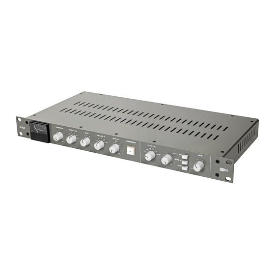
- Page 1 G BUS STEREO VCA COMPRESSOR Operation Manual...
-
Page 3: Power Input
Quick Start Guide This manual will help you get the most out of your G Bus by covering the features in-depth, but the G Bus is also designed to be easy and intuitive to use, so if you’d rather play around than read, just follow the steps below: •... -
Page 4: Front Panel Description
Front Panel Description THRESHOLD : Sets the gain level at which compression starts. The clockwise position is maximum (least sensitive), turn counterclockwise to lower the threshold. ATTACK : Sets the attack time of the compressor, measured in milliseconds. RATIO : Sets the ratio of the compression between 2:1, 4:1, and 10:1 (depending on calibration). RELEASE : Sets the release time of the compressor, measured in seconds. -
Page 5: Rear Panel Description
: DC power input from the external power supply. THRU : Used for powering multiple DIYRE units from a single, external power supply. Compatible units include G BUS COLOUR DUO , and PR502 . To daisy chain, run a 5-pin XLR cable from the... -
Page 6: Block Diagram
Block Diagram Audio enters the G Bus through the input amplifier, which converts the signal from balanced to unbalanced. It then splits to three places: the mix circuit, the rest of the audio path, and the sidechain (SC). In the mix circuit, the output from the balanced input is summed with the output from the audio VCA. The following switch selects between the output from the VCA (default) and the output of the mix circuit. -
Page 7: Specifications
Specifications Line Input Impedance: 10kΩ Max Input Level: 27.5dBu Line Output Output Impedance: 100Ω Max Output Level: +22dBu General Make-up Gain: 25dB Frequency Response: ±0.2dB 20Hz to 20kHz rel. 1kHz Noise: -85dBu, 20Hz to 20kHz, input terminated with 600 Ohms Power Rails: ±16vDC, ±12vDC, +48vDC Wall Power: 100-240VAC, ~50/60Hz 2.5A Dimensions... - Page 8 G Bus Recall Sheet Print your own at diy.re/recall Date: Artist: Project: Track: Bus: Date: Artist: Project: Track: Bus: Date: Artist: Project: Track: Bus: Date: Artist: Project: Track: Bus: Date: Artist: Project: Track: Bus: Date: Artist: Project: Track: Bus:...
-
Page 9: Replacement Parts
Replacement Parts Below is a list of off-the-shelf components (other than custom parts) should you need a replacement down the road. For parts listed ‘DIYRE’ please contact us for replacements at diy.re/contact REFERENCE DESIGNATOR VALUE MAN. PART NUMBER SOURCE Front panel screws 6-32, 1/4"... - Page 11 As with any electronic device, operating the G Bus safely requires some common sense and respect for the dangers of electrical power. Treat your G Bus like a hair dryer. Don’t turn it on when it’s wet, only clean it with a dry cloth, and if you spill a liquid on it unplug it immediately and don’t turn it back on until it’s been repaired by a tech.
Need help?
Do you have a question about the G BUS and is the answer not in the manual?
Questions and answers