Table of Contents
Advertisement
Quick Links
Advertisement
Table of Contents

Related Manuals for Quanser Aero 2


Summary of Contents for Quanser Aero 2
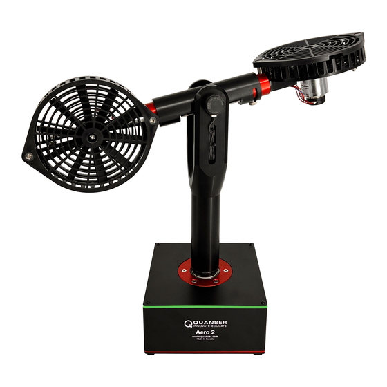
- Page 1 Aero 2 User Manual V2.1 – Dec 12 , 2022...
- Page 2 This document and the software described in it are provided subject to a license agreement. Neither the software nor this document may be used or copied except as specified under the terms of that license agreement. Quanser Inc. grants the following rights: a) The right to reproduce the work, to incorporate the work into one or more collections,...
- Page 3 This equipment is designed to be used for educational and research purposes and is not intended for use by the public. The user is responsible to ensure that the equipment will be used by technically qualified personnel only. While the Caution end-effector board provides connections for external user devices, users are responsible for certifying any modifications or additions they make to the default...
-
Page 4: Table Of Contents
Table of Contents Table of Contents Presentation Configuration System Schematic Handling and Setup Hardware Components DC Motors Propellers iii. Encoders Inertial Measurement Unit (IMU) Power Supply Specifications Balancing Environmental Electrical Considerations... -
Page 5: Presentation
PWM amplifier with integrated current sense. Rotary encoders are used to measure the angular position of the Aero 2 in both degrees of freedom, as well as the position of the thruster motors. The velocity of these encoders can be measured using the included software tachometers. - Page 6 Interface power LED Pitch pivot Data connector (USB version shown) Pitch lock Power connector Yaw lock Power switch Thruster rotation locks Yaw encoder and slip ring Base LEDs Aero 2 QFLEX 2 internal data bus Table 1. Quanser Aero 2 Components...
-
Page 7: Configuration
System Schematic The Quanser Aero 2 can be configured with one of two different I/O interfaces: the QFLEX 2 USB, and the QFLEX 2 Embedded. The QFLEX 2 USB provides a USB interface for use with a computer. The QFLEX 2 Embedded provides a 4-wire SPI interface for use with an external microcontroller board. -
Page 8: Handling And Setup
Figure 4. Interaction between Quanser Aero 2 system components Handling and Setup When moving the Quanser Aero 2, lift it by gripping the support yolk just above the yaw pivot. Support the base with your other hand. Do not lift the Aero 2 by the Aero body. -
Page 9: Hardware Components
Power Supply The Quanser Aero is equipped with an external DC power supply which provides 24.0 V power at up to 2.71 A for the sensors and motors. This supply is intended for use with 100-240 VAC at 50-60 Hz. -
Page 10: Specifications
Specifications Table 2.2 lists and characterizes the main parameters associated with the Quanser Aero.. Symbol Description Value Units DC Motor Nominal input voltage �� 18.0 Volts ������ Nominal torque �� 22.0 mN ∙ m ������ Nominal angular velocity ��̇ 3050 Nominal current ��... -
Page 11: Balancing
Figure 6. Mass sliders for leveling the Aero 2 unit Start by moving the sliding masses all the way outwards. If the Aero 2 is not balanced, identify the rotor that is leaning downwards. Move the mass slider on this rotor inwards until the system is balanced. -
Page 12: Electrical Considerations
Always monitor the current draw and motor temperature to ensure that you do not exceed the Caution maximum current draw or 50℃. Do not allow conductive material to touch the Aero 2 core board as it can short and damage the Caution electronics.
Need help?
Do you have a question about the Aero 2 and is the answer not in the manual?
Questions and answers